
-
-
X Base 2040 Profiles (x2)
-
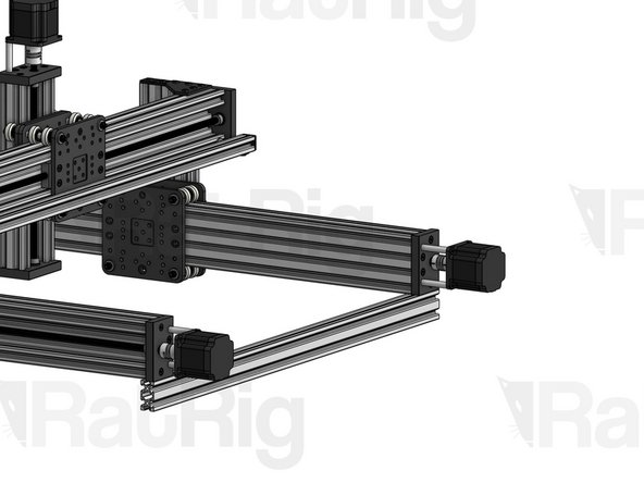
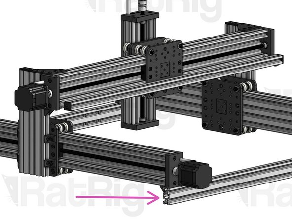
Y C-Beam Profiles (x2). Slide them inside the X-Gantry carriages.
-
-
-
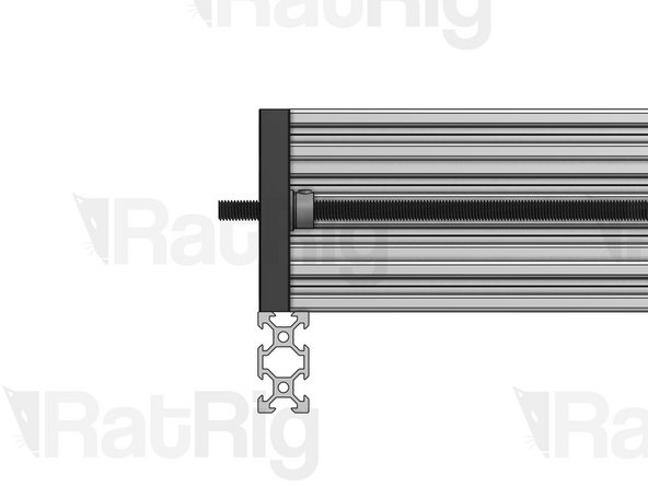
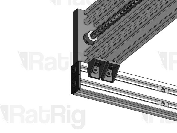
Fasten the 2 Y Lead Screws through the Nut Blocks on the X-Gantry carriages.
-
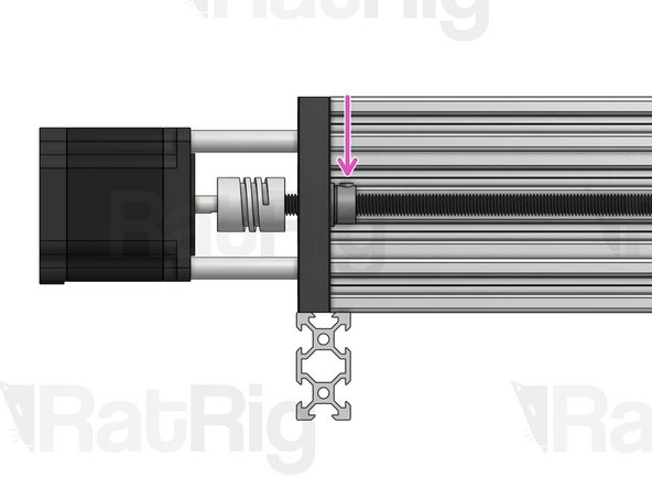
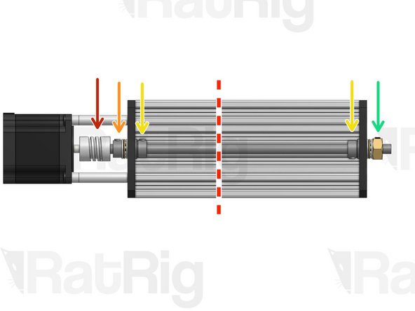
Once you're done, you should see about 2cm (variants 500x500/750x750) or 3cm (variant 1250x1250) of lead screw coming out of each end of each C-Beam.
-
Y Lead Screws (x2)
-
-
-
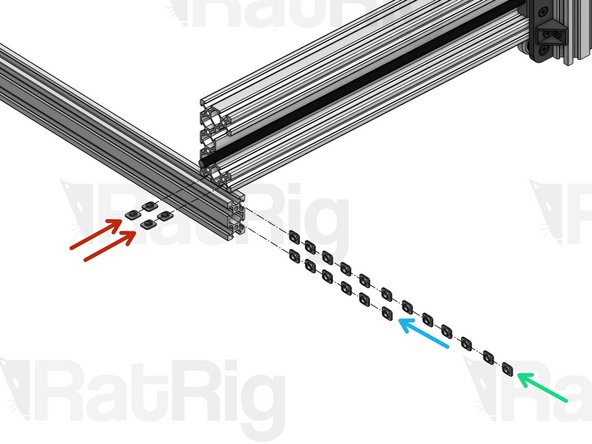
Take note of the correct orientation for insertion (flat side facing outwards).
-
Count a total of 44 T-Nuts M5
-
Insert 2 T-Nuts inside each of the bottom slots of both Y C-Beam profiles (8 T-Nuts in total, 4 for each C-Beam)
-
Insert 6 on the bottom side slot of both X Base 2040 profiles (12 in total)
-
Insert 12 on the top side slot of both X Base 2040 profiles (24 in total)
-
-
-
If you're building a Lead CNC 1250x750, your End Mounts are different. Skip to step 6.
-
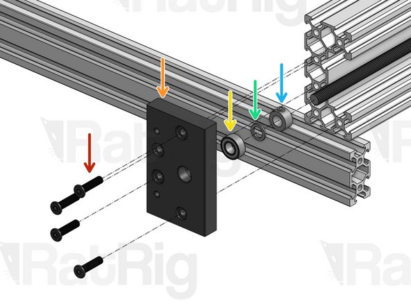
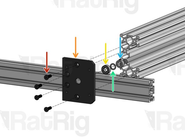
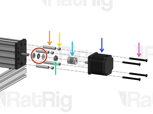
Repeat this step 4 times, one for each C-Beam End.
-
Low Profile Screw M5x20mm
-
C-Beam End Mount
-
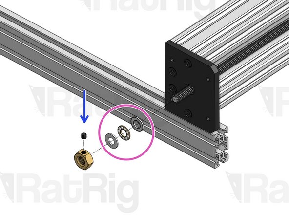
688ZZ Ball Bearing
-
Precision Shim 12x8x1mm
-
Lock Collar 8mm. Set it in position, but don't tighten it for now.
-
-
-
If you're building a Lead CNC 1250x750, your End Mounts are different. Skip to step 6.
-
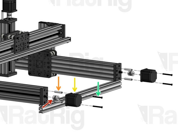
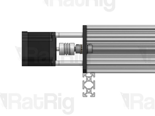
Flexible Coupling - 1/4" x 8mm. Align the Set Screw on the coupling with the flat face of the D shaped motor shaft and tighten it. Then tighten the Set screw on the lead screw side. Finally, tighten both clamping bolts on the coupling.
-
Aluminium Spacer 40mm
-
Nema 23 Motor
-
Low Profile Screw M5x50mm
-
Press the Lock Collars you inserted in the previous step against their respective C-Beam End Mounts and tighten their Set Screw, to lock the position of the bearings and shims straight against the End Mounts.
-
The next 3 steps are only relevant for the Lead CNC 1510. Skip to step 9.
-
-
-
(If you're NOT building a Lead CNC 1250x750, skip to step 9). This step should be repeated twice, on the 2 Y C-Beam ends on the front side of the machine (when you're facing the front of the machine, the X Gantry Motor is on the right side).
-
Low Profile Screw M5x15mm
-
C-Beam Motor Mount Plate
-
688ZZ Ball Bearing
-
Precision Shim 12x8x1mm
-
Tensioner Nut. For now, screw it in just a tiny bit, so it holds its position.
-
Thrust Bearing
-
-
-
(If you're NOT building a Lead CNC 1250x750, skip to step 9). This step should be repeated twice, on the 2 Y C-Beam ends on the rear side of the machine (when you're facing the rear of the machine, the X Gantry Motor is on the left side).
-
Thrust Bearing
-
Aluminium Spacer 40mm
-
Aluminium Spacer 6mm
-
Lock Collar 8mm. Set in position, don't tighten yet.
-
Flexible Coupling - 1/4" x 8mm. Set in position, don't tighten yet.
-
Nema 23 Motor
-
Low Profile Screw M5x55mm
-
-
-
(If you're NOT building a Lead CNC 1250x750, skip to step 9). This step should be repeated twice, on both Y C-Beam profiles.
-
Start by adjusting the position of the Flexible Coupling to make sure that both the Lead Screw and the Nema 23 motor shaft are fully inserted inside the ends of the coupling.
-
Make sure the flat face of the D shaped motor shaft is facing the set screw on the Flexible Coupling. Tighten down the set screws on both sides, then tighten down the larger clamping screws on your coupling.
-
Press the lock collar against the Y plate and firmly tighten down its set screw.
-
Grab your X-Gantry Carriage firmly, so it doesn't move, and use a spanner to tighten the Tensioner nut until your lead screw is under tension. Then, tighten the set screw on the Tensioner nut to lock it in place.
-
Excessive tension should be avoided, as it will increase part wear. You may need to adjust tension once you start using the machine, if you notice whip/vibration on the lead screw.
-
Press these lock collars against their respective End Plates and tighten down their set screws.
-
-
-
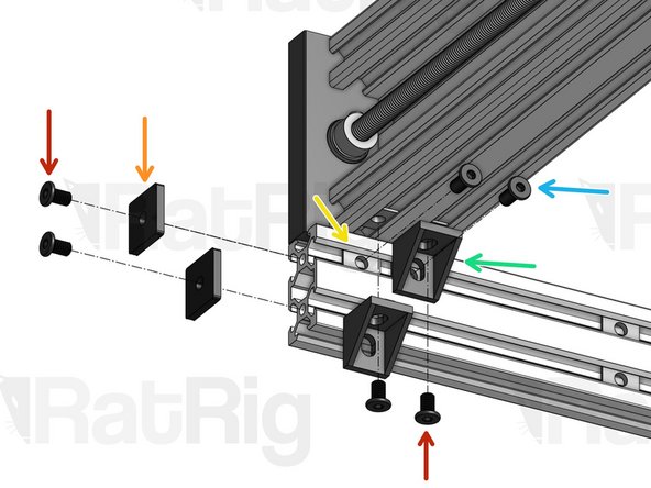
Repeat this step 4 times, on each corner of your base frame.
-
Do not fully tighten the Cast Corners at first. Leave them slightly loose and make sure your frame is perfectly square first. Squareness is really important - get a friend's help if you can. Best way to check squareness is to measure the diagonals of the rectangle formed by the 4 profiles. They should have the exact same length.
-
Low Profile Screw M5x8mm
-
2020 End Cap
-
T-Nut M5 (inserted in the slot on step 3)
-
Low Profile Screw M5x10mm
-
Cast Corner
-
Do not install Endcaps on this corner (this is where the Y Drag Chain will be connected later in the build).
-


Cancel: I did not complete this guide.
One other person completed this guide.
