-
-
Tip: images on this guide will show the gantry in the upright position, for easier visibility and understanding. However, you may find it more convenient to assemble the gantry while it lays on its side, for the first few steps.
-
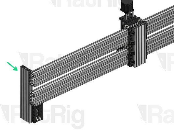
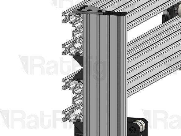
X-Gantry C-Beam (x2).
-
Note the orientation of the C-Beam profile (flat face on the spindle side)
-
XZ Carriage
-
-
-
Repeat this step on both ends of each C-Beam
-
T-Nut M5 (x28).
-
Note the orientation of the T-Nuts (flat side always faces outwards)
-
-
-
Repeat this Step on both sides of the C-Beam.
-
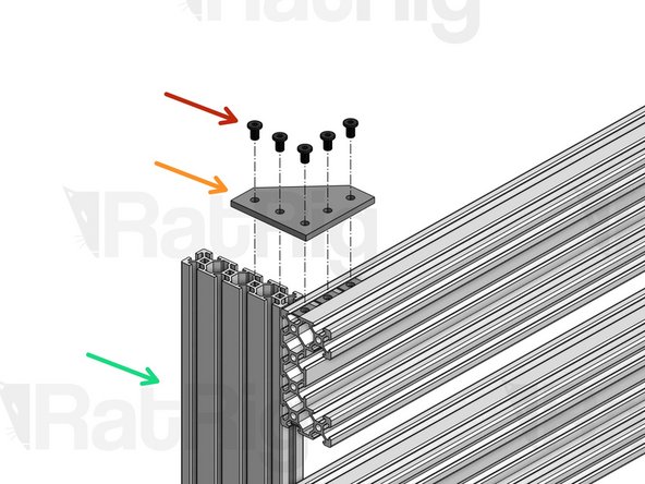
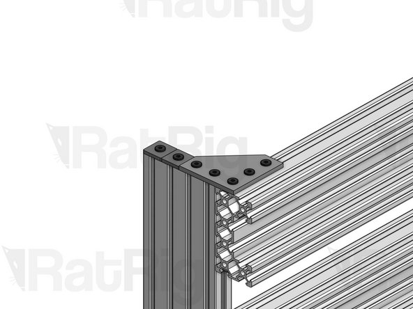
Align the Y carriages with the ends of the X-Gantry C-Beam profiles.
-
Low Profile Screw M5x8mm
-
90º Joining Plate
-
Y Carriage 2080
-
-
-
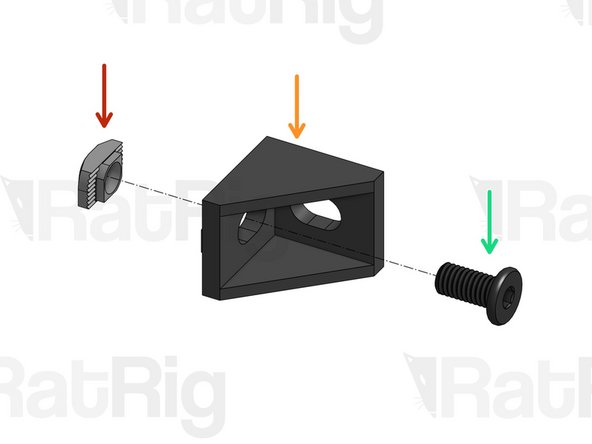
Repeat this step for 16 Cast Corners
-
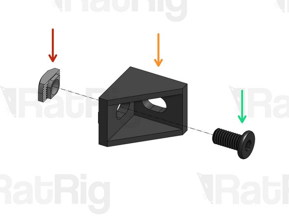
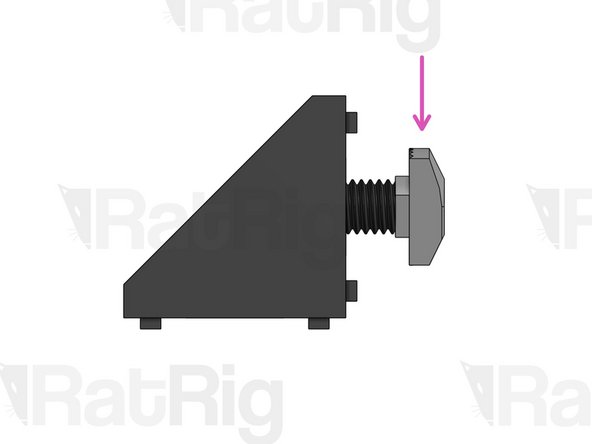
Drop-in T-Nut M5
-
Cast Corner
-
Low Profile Screw M5x10mm
-
Screw T-Nut into position, but don't tighten!
-
-
-
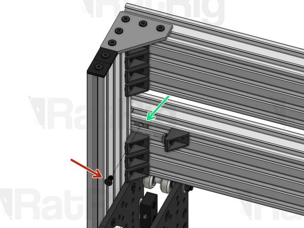
Connect 8 Cast Corners on each side of your Gantry (16 in total)
-
Low Profile Screw M5x8mm (x16)
-
T-Nut M5 (inserted on step 2)
-
-
-
Repeat this step for 6 Cast Corners
-
Drop-in T-Nut M5
-
Cast Corner
-
Low Profile Screw M5x8mm
-
Screw T-Nut into position, but don't tighten!
-
-
-
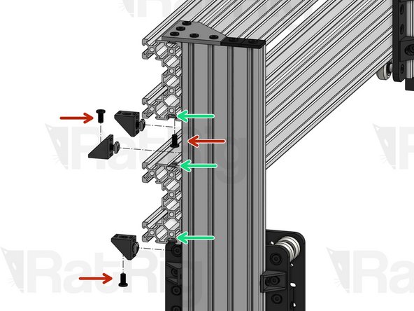
Reinforce the connection with 3 Cast Corners on each side of your gantry
-
Low Profile Screw M5x10mm
-
T-Nut M5 (inserted in the slot on step 2)
-
-
-
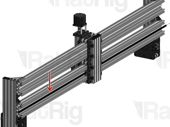
X Lead Screw. Fasten it through the Nut Blocks on the X carriage until there's about 2cm of lead screw coming out of each side of the C-Beam.
-
-
-
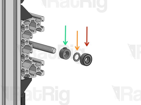
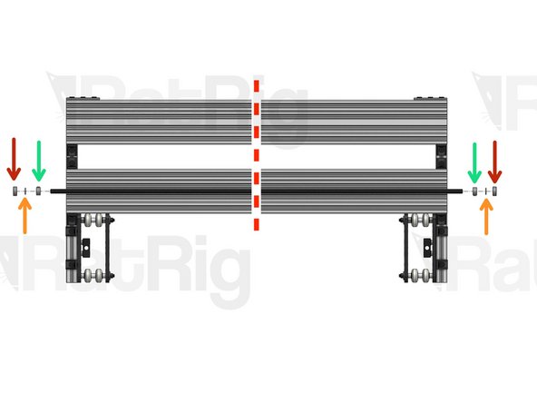
688ZZ Ball Bearing
-
Precision Shim 12x8x1mm
-
Lock Collar 8mm.
-
Slide these components on both sides of the X Lead Screw. Pay attention to the order of insertion on each side (it's mirrored).
-
-
-
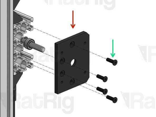
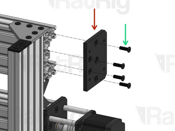
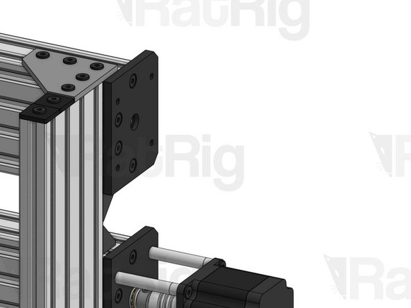
C-Beam Motor Mount Plate
-
Low Profile Screw M5x15mm
-
Repeat this step on the opposite side of the C-Beam
-
-
-
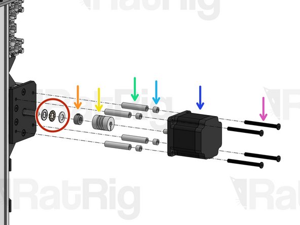
Thrust Bearing
-
Lock Collar 8mm. Set in position, don't tighten yet.
-
Flexible Coupling - 1/4" x 8mm. Set in position, don't tighten yet.
-
Aluminium Spacer 40mm
-
Aluminium Spacer 6mm
-
Nema 23 Motor
-
Low Profile Screw M5x55mm
-
-
-
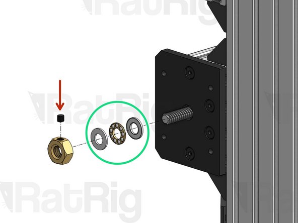
Thrust Bearing
-
Tension Nut. For now, screw it in just a tiny bit, so it holds its position.
-
-
-
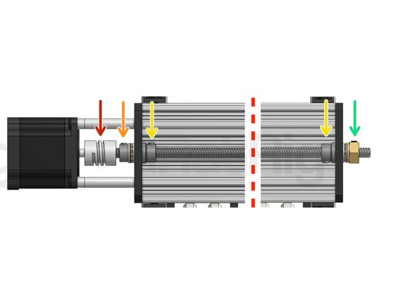
Start by adjusting the position of the Flexible Coupling to make sure that both the Lead Screw and the Nema 23 motor shaft are fully inserted inside the ends of the coupling.
-
Make sure the flat face of the D shaped motor shaft is facing the set screw on the Flexible Coupling. Tighten down the set screws on both sides.
-
Tighten down the larger clamping screws on your coupling.
-
Press the lock collar against the Y plate and firmly tighten down its set screw.
-
Grab your XZ Carriage firmly, so it doesn't move, and use a spanner to tighten the Tensioner nut until your lead screw is under tension. Excessive tension should be avoided, as it will increase part wear. You may need to adjust tension once you start using the machine, if you notice whip/vibration on the lead screw.
-
Instead of grabbing the carriage, you can also manually spin the lead screw until the carriage has reached its right-most position. In this position the carriage can't move once you start tightening the Tensioner Nut.
-
Press these 2 lock collars against their respective Y Plates and tighten down their set screws.
-
-
-
C-Beam Motor Mount Plate
-
Low Profile Screw M5x15mm
-
Repeat this step on the opposite side of the C-Beam
-
-
-
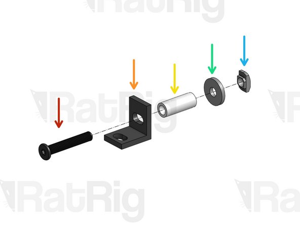
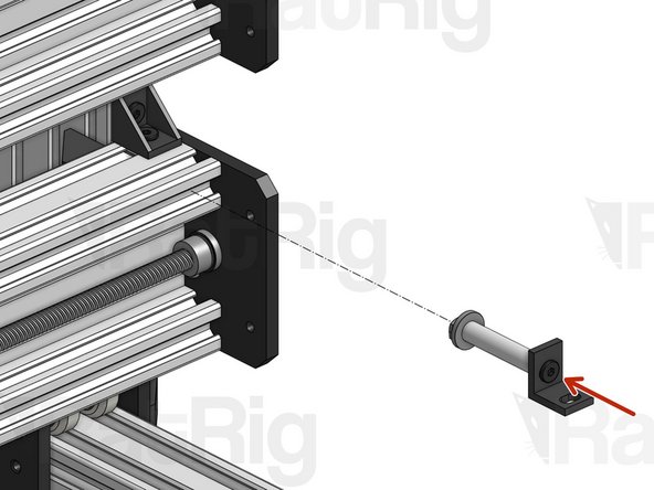
Low Profile Screw M5x50mm
-
Single L Bracket
-
Aluminium Spacer 40mm
-
Slot Washer 15x5x2mm
-
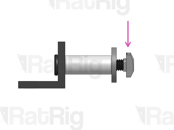
Drop-in T-Nut M5
-
Screw T-Nut into position, but don't tighten yet.
-
Repeat this step twice (you will need 2 mounts)
-
-
-
Attach the 2 Cable Tray Mounts at about 10mm from each end of the C-Beam. Tighten the screw while making sure the L bracket doesn't twist.
-
-
-
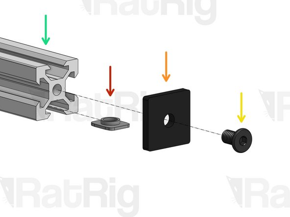
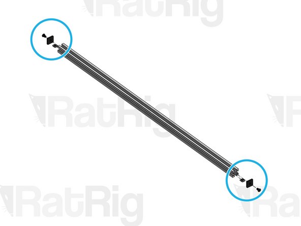
X-Gantry 2020 profile
-
T-Nut M5
-
Endcap 2020
-
Low Profile Screw M5x8mm
-
Repeat step on both sides of the 2020 profile
-
-
-
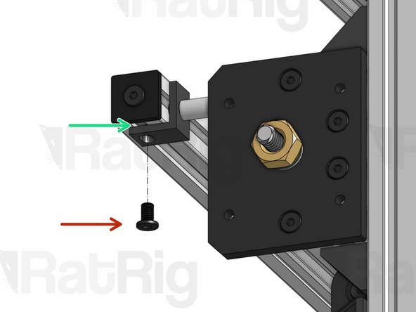
Low Profile Screw M5x8mm
-
T-Nut M5 (inserted in the slot on Step 18)
-
Repeat this step on both sides of the 2020.
-