Steps
15
- V-Core 4 - Electronics enclosure V2 15 steps

In Progress
This guide is currently being written. Reload periodically to see the latest changes.

Private
This guide will not appear in search results and can only be viewed by team members!
Quiz
0
-
-
vc4_enclosure_steel_base
-
vc4_enclosure_steel_top
-
vc4_enclosure_steel_left
-
vc4_enclosure_steel_bottom
-
vc4_enclosure_steel_right
-
3x vc4_Enclosure_corner_steel + 1x vc4_Enclosure_corner_hole_steel_V2
-
16x M3x6 Button Head Screw
-
4x M3x6 Countersink Screw
-
-
-
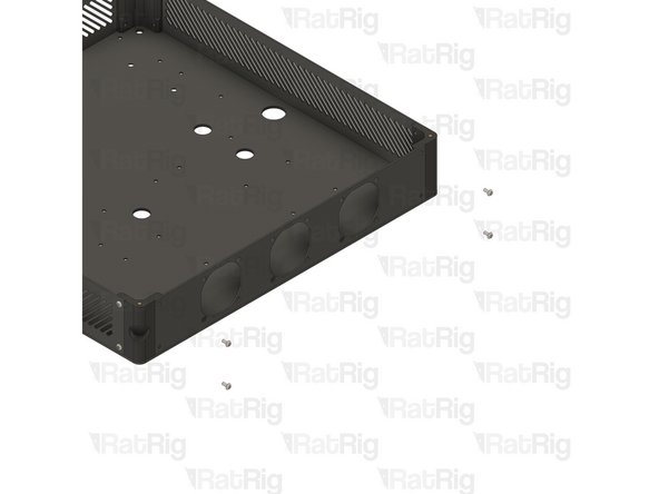
vc4_enclosure_steel_base
-
vc4_Enclosure_steel_corner
-
M3x6 Countersink Screw
-
Assemble the components as shown, and ensure the vc4_enclosure_steel_base is correctly oriented and the countersunk screw is inserted into the countersink groove.
-
Repeat the previous Steps and assemble the remaining corners.
-
-
-
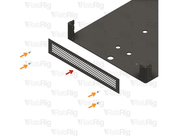
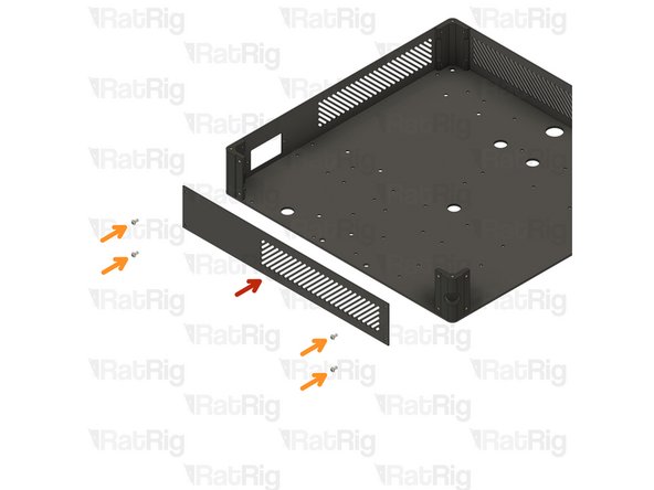
vc4_enclosure_steel_top
-
4x M3x6 Button Head Screw
-
Assemble the enclosure components as shown, making sure the panels are correctly oriented.
-
-
-
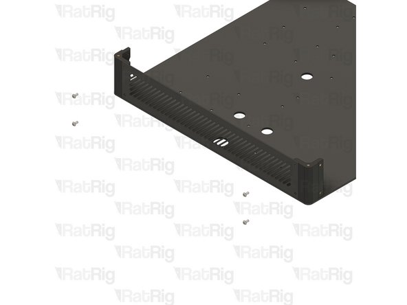
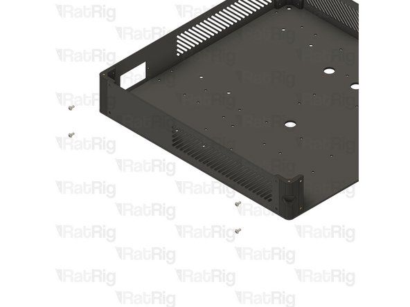
vc4_enclosure_steel_left
-
4x M3x6 Button Head Screw
-
Assemble the enclosure components as shown, making sure the panels are correctly oriented.
-
-
-
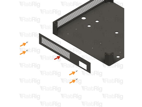
vc4_enclosure_steel_bottom
-
4x M3x6 Button Head Screw
-
Assemble the enclosure components as shown, making sure the panels are correctly oriented.
-
-
-
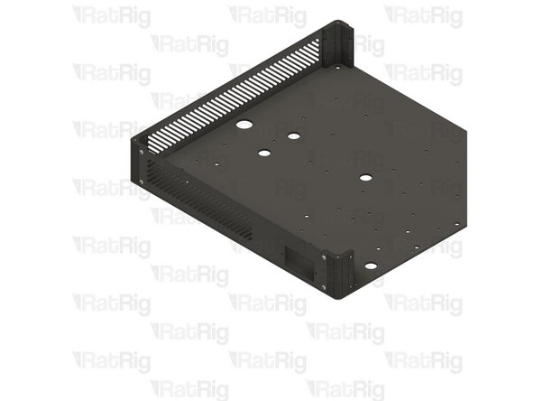
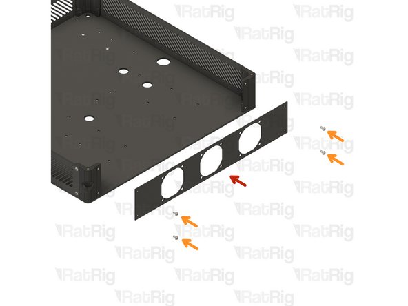
vc4_enclosure_steel_right
-
4x M3x6 Button Head Screw
-
Assemble the enclosure components as shown, making sure the panels are correctly oriented.
-
-
-
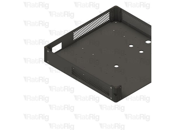
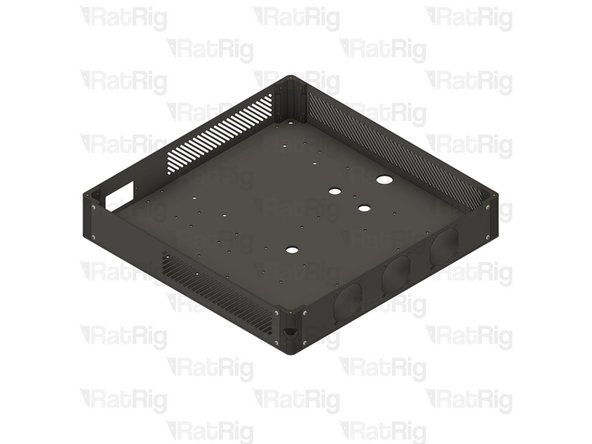
Double-check if all panels are correctly oriented and the assembly looks exactly like the picture.
-
-
-
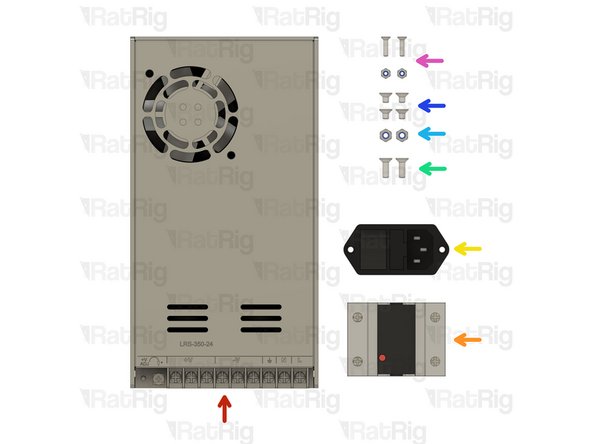
Power Supply Weho - 250Watt 24V - Fanless
-
SSR 40A480VAC Solid State Relay
-
IEC Socket - Switchable & Fused (Plain switch & 10A fuse)
-
If you received an IEC connector that resembles the one shown in the picture, please do not install it. The correct installation steps will be provided later in the guide.
-
2x M4x12 Countersink Screw
-
2x M4 Nylon Locking Nut
-
4x M4x6 Countersink Screw
-
2x M3 Nylon Locking Nut + 2x M3x12 Countersink Screw
-
-
-
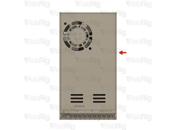
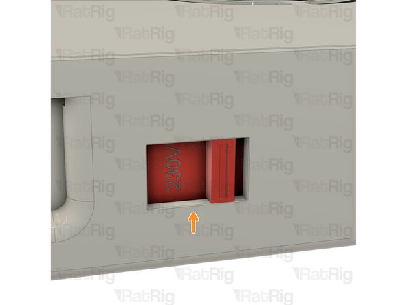
On the right side of the power supply there is a switch.
-
This switch needs to be set to the mains voltage in your country. Either 115V (most common in the USA / Canada), or 230V.
-
Setting this to the incorrect input voltage may destroy the power supply and anything connected to it.
-
-
-
Electronics Enclosure assembly
-
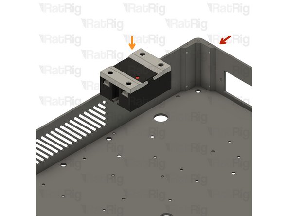
SSR 40A480VAC Solid State Relay
-
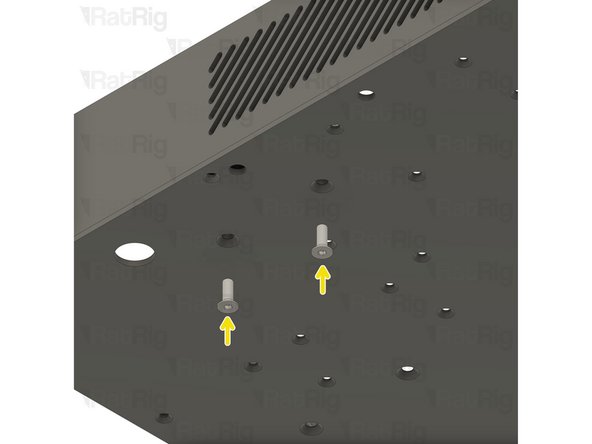
2x M4x12 Countersink screws
-
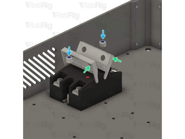
Gently open the SSR Relay tabs to access the mounting holes.
-
2x M4 Nylon Locking Nut
-
Tighten the screws to secure the SSR Relay to the electronics enclosure
-
-
-
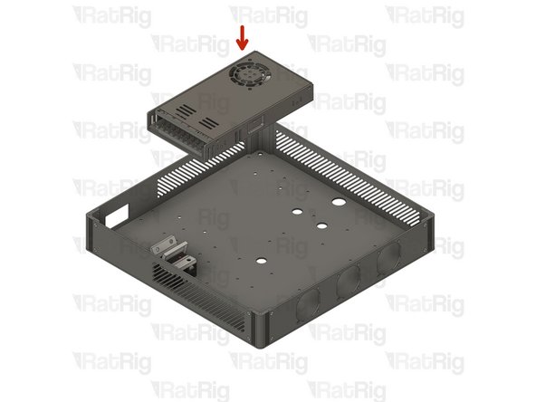
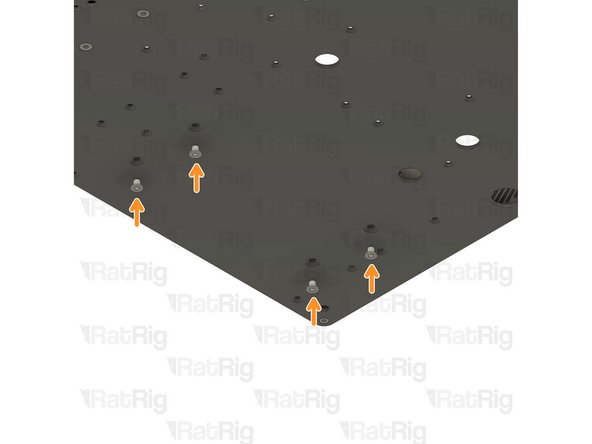
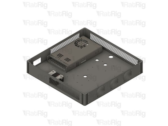
Power Supply Weho - 250Watt 24V - Fanless
-
4x M4x6 Countersink Screw
-
Mount the power supply as shown, and tighten the screws to secure it to the electronics enclosure.
-
-
-
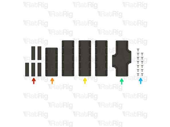
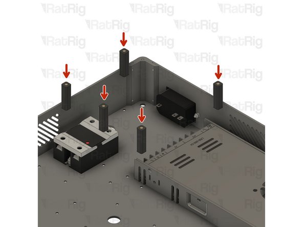
5x vc4_ac_cover_support assembly
-
vc4_cable_guide_4 assembly
-
3x vc4_cable_guide_5 assembly
-
vc4_cable_guide_cross
-
13x M3x6 Countersink Screws
-
-
-
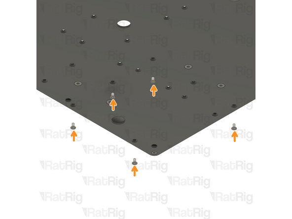
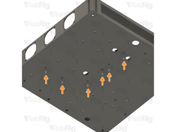
vc4_ac_cover_support assembly
-
5x M3x6 Countersink Screws
-
Insert the M3x6 Countersink Screws from the bottom, into the designated holes, and secure the vc4_ac_support assemblies to the enclosure.
-
Take care not to over-tighten the screws as you can damage the printed parts
-
-
-
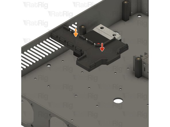
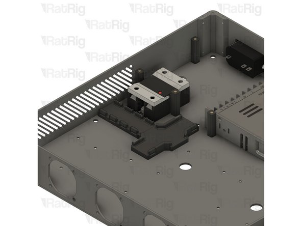
vc4_cable_guide_cross
-
vc4_cable_guide_4 assembly
-
M3x6 Countersink Screws
-
Insert the M3x6 Countersink Screws from the bottom, into the designated holes, and secure the assemblies to the enclosure.
-
Take care not to over-tighten the screws as you can damage the printed parts
-
-
-
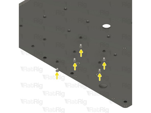
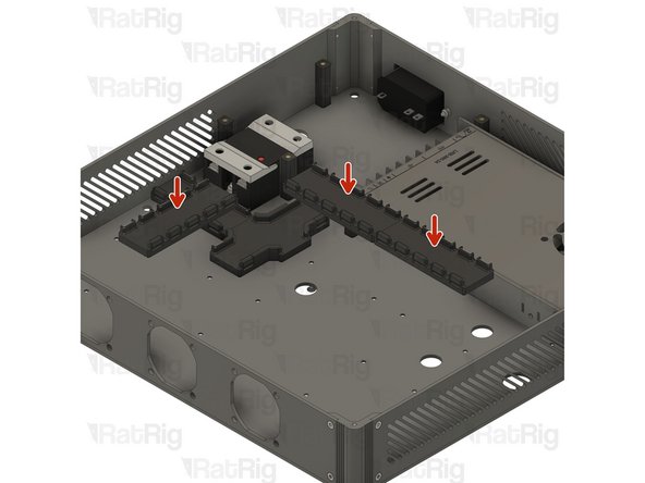
3x vc4_cable_guide_5 assembly
-
6x M3x6 Countersink Screws
-
Insert the M3x6 Countersink Screws from the bottom, into the designated holes, and secure the vc4_ac_support assemblies to the enclosure.
-
Take care not to over-tighten the screws as you can damage the printed parts
-