
Steps
18
- 00. Preparations 18 steps

User-Contributed Guide
This guide is not managed by the site's staff.
Quiz
0
-
-
Several of the V-Core 3.1 printed parts have sacrificial layers which need to be removed prior to assembly
-
It is recommended to remove them by using a screwdriver, a hex key, or a drill, to push through the layers. This clears the holes for the screws.
-
lead_screw_motor_cage_back_3.1 printed part
-
Sacrificial layers to be cleared
-
Prepared printed part
-
-
-
The following printed parts have sacrificial layers which require clearing:
-
ratrig_eva_shroud
-
2x 3030_panel_mount_horizontal
-
bed_arm_left_3.1
-
bed_arm_right_3.1
-
bed_arm_back_3.1
-
xy_motor_cage_top_left_3.1_cutout
-
xy_motor_cage_top_right_3.1_cutout
-
-
-
It is recommended to have the following tools available for assembling the V-Core 3.1:
-
Allen Key / Hex Wrenches in the following sizes: 2.5mm, 3mm, 4mm, 5mm & 6mm
-
Wire cutters & a wire stripper
-
Tape measure or calipers
-
Crimping tool
-
Cross slot / Philips screwdrivers
-
Flat / straight screwdrivers
-
Engineers Square
-
-
-
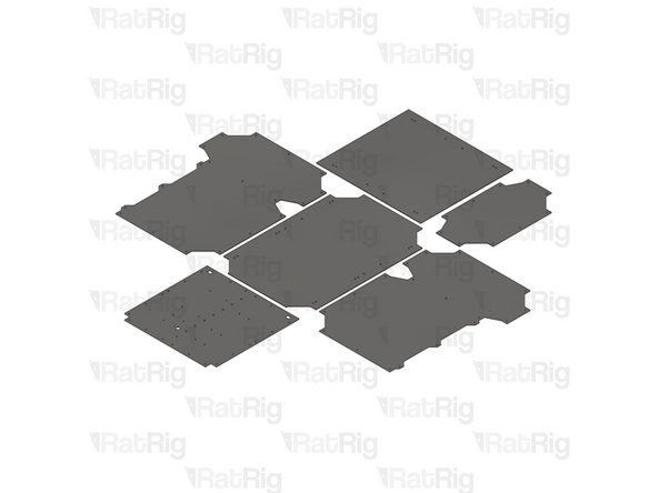
The V-Core 3.1 panels are not provided as part of the kit, and must be sourced separately
-
It is highly recommended to source the electronics panel prior to beginning the V-Core 3.1 build, as it is very difficult to install the full panel on an assembled frame
-
Source files, in multiple formats, are available for all panels on the Rat Rig GitHub repository
-
-
-
Occasionally you will need to install a hex nut into a printed part
-
The hex nut needs to be fully pulled into the printed part to ensure there are no issues with assembly or cross threading
-
This animation shows an example of how to use a cap head screw to pull a hex nut into a printed part
-
-
-
16x 3030 Corner Plate
-
80x M6x12 Cap Head Screw
-
80x 3030 Drop-in T-Nut - M6
-
-
-
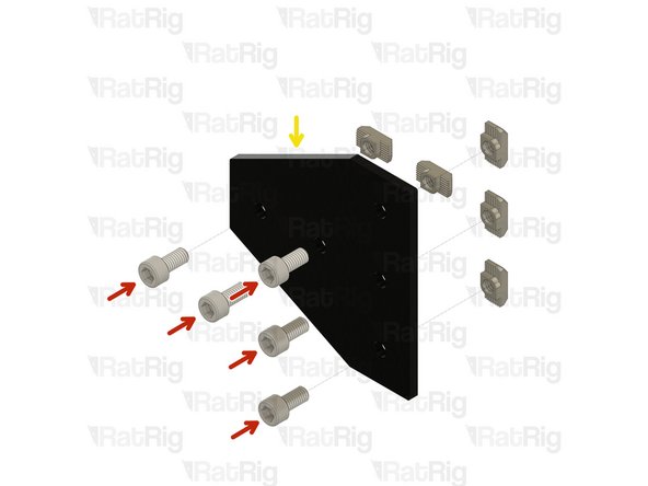
M6x12 Cap Head Screw
-
3030 Drop In T-Nut M6
-
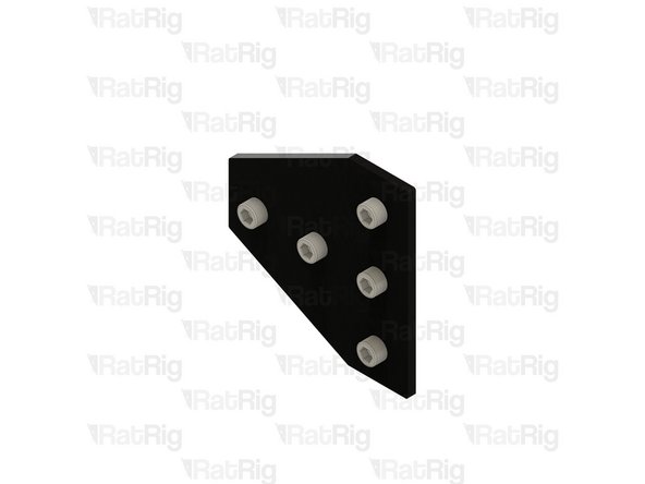
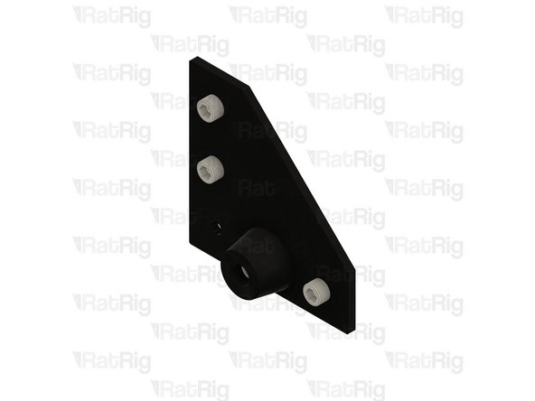
Corner Joining Plate for 3030
-
Loosely thread the 3030 T-Nuts onto the M6x12 screws. Do not tighten them at this point.
-
-
-
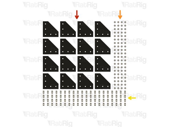
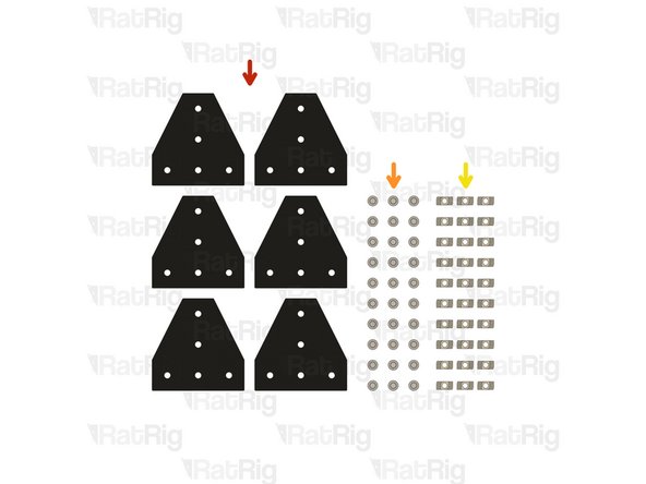
6x T-Shape Joining Plate for 3030
-
30x M6x12 Cap Head Screw
-
30x 3030 Drop-in T-Nut - M6
-
-
-
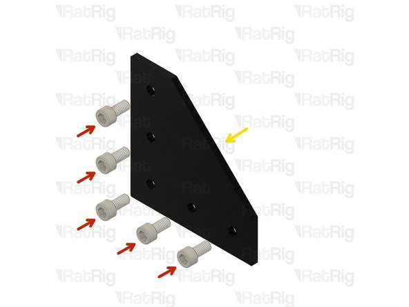
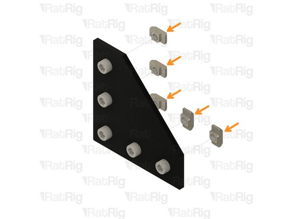
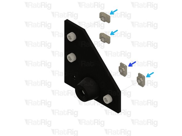
M6x12 Cap Head Screw
-
3030 Drop In T-Nut - M6
-
T-Shape Joining Plate for 3030
-
Loosely thread the 3030 T-Nuts onto the M6x12 screws. Do not tighten them at this point.
-
-
-
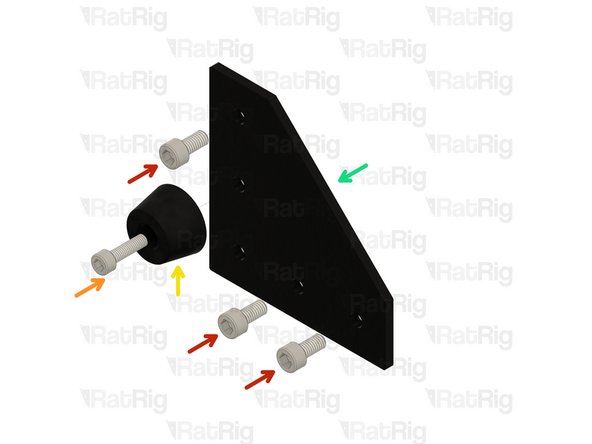
4x 3030 Corner Plate
-
12x M6x12 Cap Head Screw
-
12x 3030 Drop-in T-Nut - M6
-
4x Rubber Foot with Metal Insert
-
4x M5x18 Cap Head Screw
-
4x 3030 Drop-in T-Nut - M5
-
-
-
M6x12 Cap Head Screw
-
M5x18 Cap Head Screw
-
Rubber Foot with Metal Insert
-
3030 Corner Plate
-
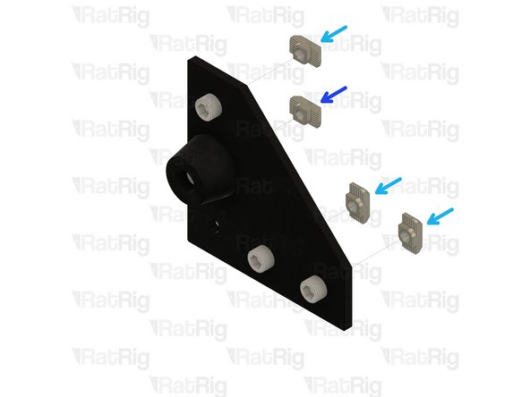
3030 Drop-in T-Nut - M6
-
3030 Drop-in T-Nut - M5
-
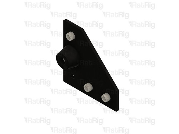
Loosely thread the 3030 T-Nuts onto the screws. Do not tighten them at this point.
-
-
-
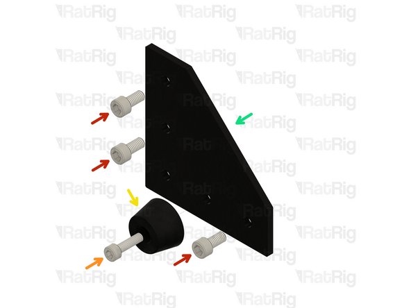
M6x12 Cap Head Screw
-
M5x18 Cap Head Screw
-
Rubber Foot with Metal Insert
-
3030 Corner Plate
-
3030 Drop-in T-Nut - M6
-
3030 Drop-in T-Nut - M5
-
Loosely thread the 3030 T-Nuts onto the screws. Do not tighten them at this point.
-
-
-
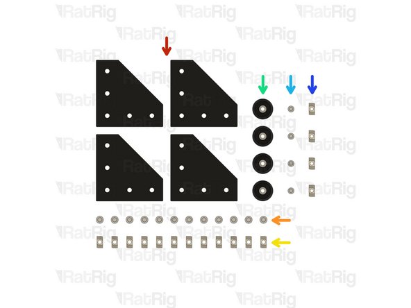
12x 90 Degree Cast Corner
-
24x M6x12 Cap Head Screw
-
24x M6 Washer
-
24x 3030 Drop-in T-Nut - M6
-
-
-
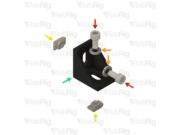
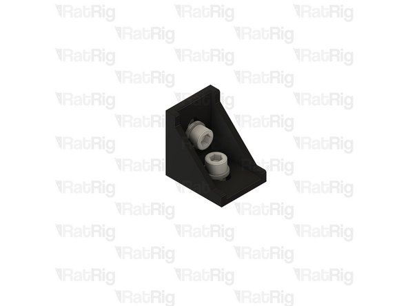
M6x12 Cap Head Screw
-
M6 Washer
-
3030 Drop-in T-Nut - M6
-
Cast 90 Degree Corner Bracket for 3030
-
Loosely thread the 3030 T-Nuts onto the M6x12 screws. Do not tighten them at this point.
-
-
-
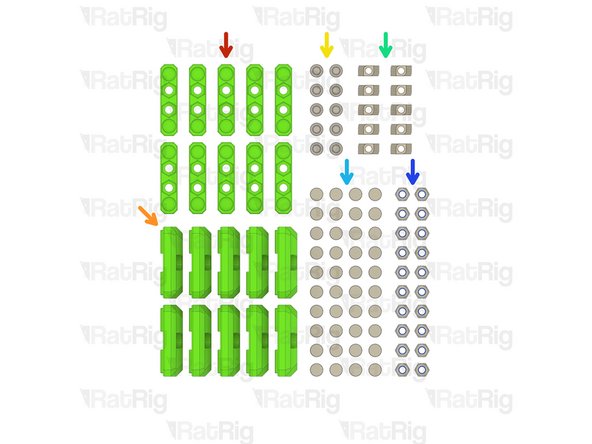
10x panel_magnet_holder printed part
-
10x panel_magnet_mount printed part
-
10x M6x12 Cap Head Screw
-
10x 3030 Drop-in T-Nut - M6
-
40x Neodymium Disc Magnet - 10x4mm
-
20x M6 Nylon Locking Hex Nut
-
-
-
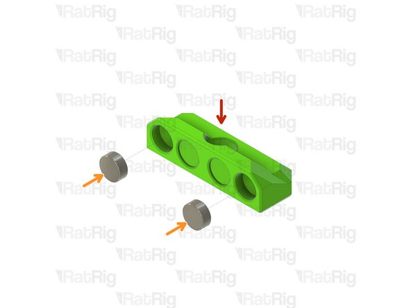
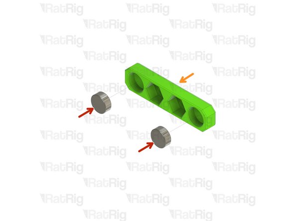
panel_magnet_mount printed part
-
Neodymium Disc Magnet - 10x4mm
-
The magnets are designed to be a tight fit into the printed part. If they are loose, or you wish to secure them further, place a few drops of cyanoacrylate glue into the printed part before adding the magnet
-
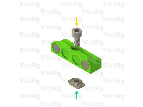
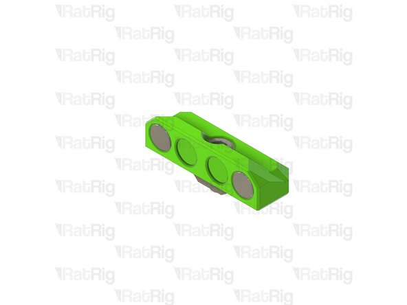
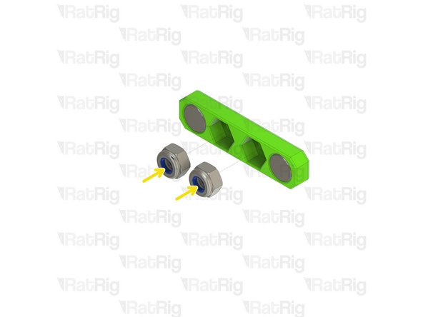
M6x12 Cap Head Screw
-
3030 Drop-in T-Nut - M6
-
Loosely thread the 3030 T-Nuts onto the M6x12 screws. Do not tighten them at this point.
-
-
-
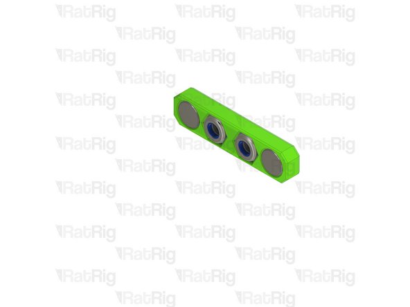
Neodymium Disc Magnet - 10x4mm
-
panel_magnet_holder printed part
-
Pay attention to the orientation of the magnets when installing them into the printed parts. Use the assemblies from the previous step to verify the magnets attract to each other, rather than repel from each other!
-
The magnets are designed to be a tight fit into the printed part. If they are loose, or you wish to secure them further, place a few drops of cyanoacrylate glue into the printed part before adding the magnet
-
M6 Nylon Locking Hex Nut
-


Cancel: I did not complete this guide.
15 other people completed this guide.