Introduction
Please note: All measurements provided in this guide are based on building a 300x300 V-Core 4.
If you are building a machine of a different size, the following adjustments can be made to the stated extrusion and linear rail lengths:
- 400x400: Add 100mm
- 500x500: Add 200mm
It is strongly recommended to assemble the frame on a known flat surface (such as a solid table, work surface or similar). Assembling the frame on a carpeted floor, tile floor or other non-flat surface can cause the finished frame to not be square. This can cause issues with print quality and performance.
-
-
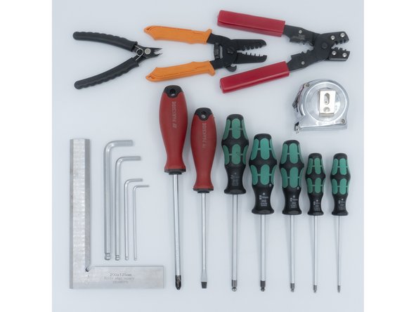
The following tools are required for this section of the guide:
-
Allen key / hex wrenches in the following sizes: 4mm & 5mm
-
Avoid using ball end hex wrenches on the Quick Connectors as they are more prone to damaging the heads of the Set Screws
-
Spanners / wrenches in the following size: 13mm
-
A pair of scissors
-
The following tools are recommended for this guide:
-
A tape measure
-
An engineer square
-
-
-
The following steps show how the aluminium extrusion quick connectors are prepared and installed. The V-Core 4.0 frame assembly begins on step 7
-
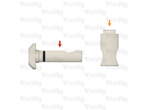
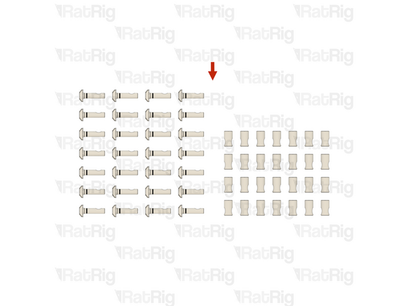
The Quick Connectors are supplied in two parts:
-
Quick Connector T-Nut Pin with the O-Ring pre-installed
-
Quick Connector Housing with the Set Screw pre-installed
-
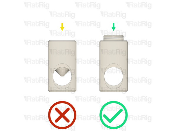
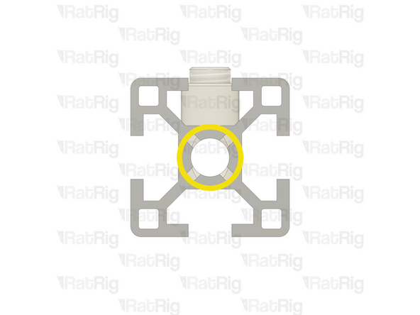
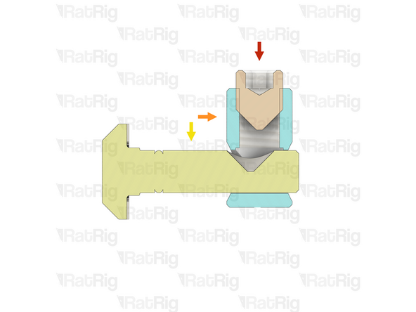
Before trying to install a Quick Connector Housing into an extrusion, check that the Set Screw is not blocking the hole in the Quick Connector Housing
-
If the Set Screw is blocking the hole in the Quick Connector Housing, slightly unscrew it to achieve the necessary clearance
-
-
-
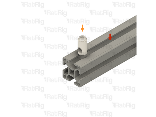
Example extrusion
-
Quick Connector Housing
-
Insert the Quick Connector Housing into the hole on the aluminium extrusion
-
Please note: If the Quick Connector Housing is difficult to insert into the aluminium extrusion, try inserting it from the opposite side
-
Make sure that the Quick Connector Housings all face the same direction
-
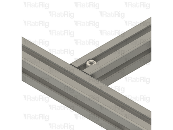
Make sure that the hole in the Quick Connector Housing is aligned with the central hole on the aluminium extrusion as shown
-
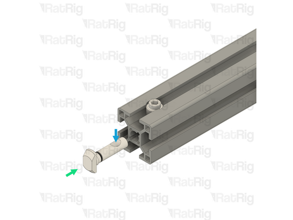
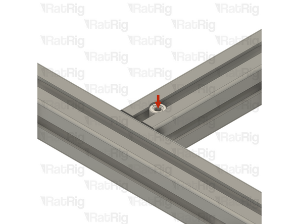
Insert the Quick Connector T-Nut pin into the central hole on the extrusion slot
-
Make sure the "notch" in the pin is facing towards the Set Screw
-
-
-
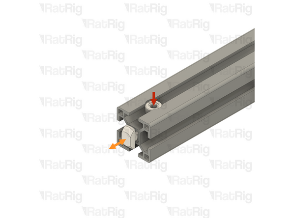
Quick Connector Set Screw
-
Using a 4mm hex key, tighten the Set Screw just enough to hold the Quick Connector T-Nut Pin inside the extrusion
-
If correctly tightened, the Quick Connector T-Nut Pin should still move slightly backwards and forwards, but should not come loose
-
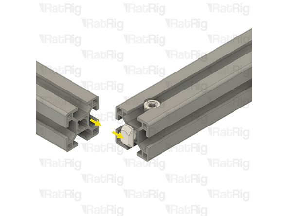
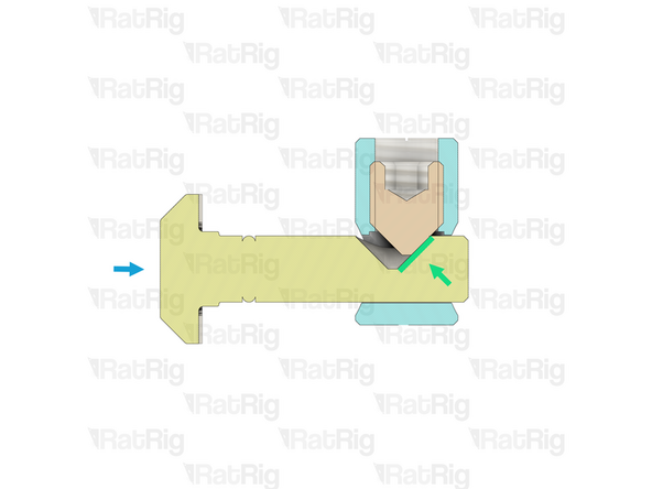
Slide the second aluminium extrusion into position, aligning the Quick Connector T-Nut Pin into the slot of the second aluminium extrusion
-
Be careful not to scratch the aluminium extrusions when assembling them
-
-
-
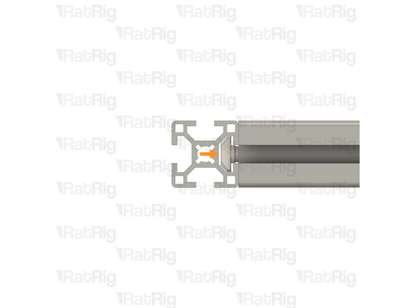
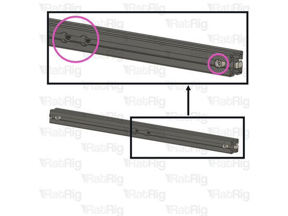
Quick Connector Housing Set Screw
-
Fully tighten the Set Screw to secure the extrusions together
-
The Set Screw will cause the Quick Connector T-Nut Pin to pull tight against the second extrusion, securing them together
-
If the extrusion connection is loose after fully tightening the Set Screw, loosen the Set Screw and check that the Quick Connector T-Nut Pin was properly positioned. The connection will not tighten if the "notch" on the pin is not aligned with the Set Screw
-
-
-
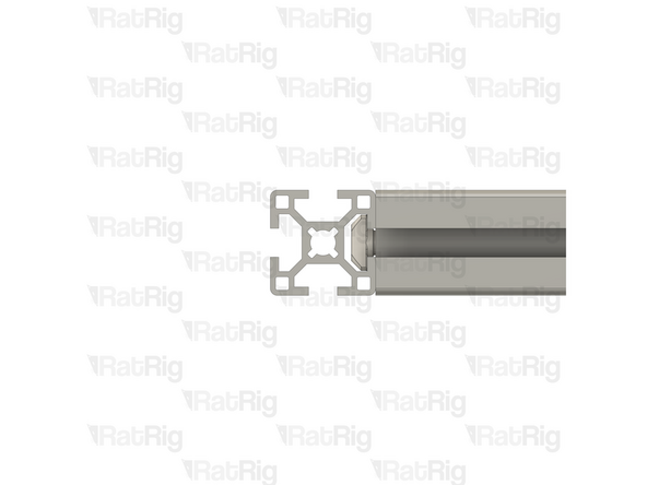
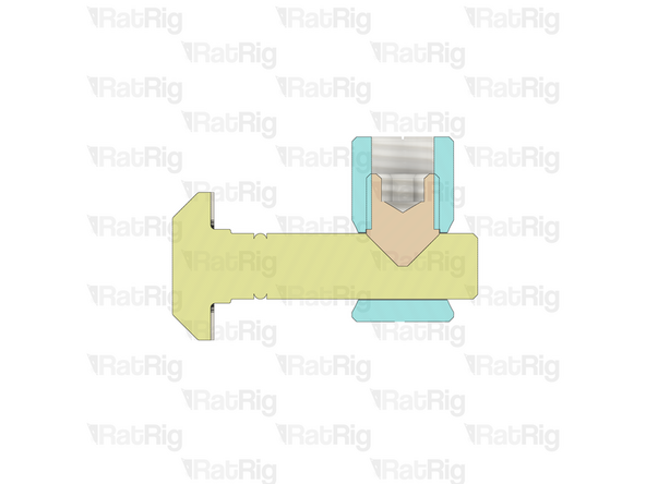
Set Screw
-
Quick Connector Housing
-
Quick Connector T-Nut Pin
-
The Set Screw within the Quick Connector Housing engages with the "notch" in the Quick Connector T-Nut Pin
-
As the Set Screw is fastened, the T-Nut Pin is pulled inwards, causing the extrusions to lock together
-
-
-
As mentioned in the introduction, all extrusion and linear rail measurements in this guide are given based on a V-Core 4.0 in the 300 size
-
If you are building a machine of a different size, the following adjustments can be made to the stated extrusion and linear rail lengths:
-
V-Core 4.0 - 400: Add 100mm to all measurements
-
V-Core 4.0 - 500: Add 200mm to all measurements
-
-
-
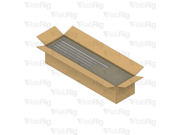
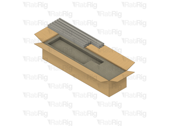
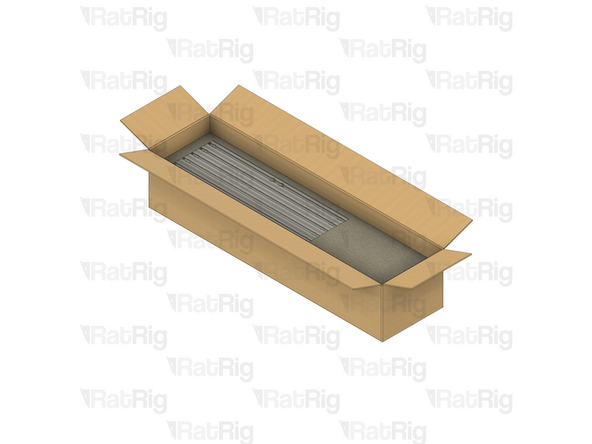
All of the extrusions for the V-Core 4.0 are provided packed in the same box. The SKU varies depending on the size being assembled:
-
V-Core 4.0 - 300: Rat Rig V-Core 4.0 - CNC Milled Profile Pack v1.0 - 300 (SKU: HW3984MK)
-
V-Core 4.0 - 400: Rat Rig V-Core 4.0 - CNC Milled Profile Pack v1.0 - 400 (SKU: HW3985MK)
-
V-Core 4.0 - 500: Rat Rig V-Core 4.0 - CNC Milled Profile Pack v1.0 - 500 (SKU: HW3986MK)
-
Be careful when opening the package. Do not use a long blade to cut the box open as you can damage the extrusions
-
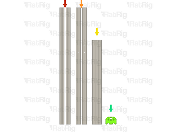
Unpack each layer carefully, placing the extrusions to the side for now
-
There are four layers of extrusions to unpack
-
The 2020 V-Slot extrusion will be used in a later guide. All others are used in the construction of the frame
-
-
-
If you are building a machine of a different size, add 100mm to all listed extrusion lengths for the V-Core 4.0 400 or 200mm for the V-Core 4.0 500
-
28x Quick Connector for 30 series B-Type - 0º (SKU: HW3347GC)
-
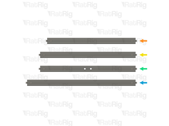
Install Quick Connectors into both ends of the following extrusions:
-
3x T-Slot 3030 Milled Extrusion - 440mm
-
4x T-Slot 3030 Milled Extrusion - 475mm
-
2x T-Slot 3030 Milled Extrusion - 475mm with two M8 holes
-
Make sure the Quick Connector Set Screws are facing the same side as the counterbores for the M8 screw holes
-
5x T-Slot 3030 Milled Extrusion - 540mm
-
-
-
If you are building a machine of a different size, add 100mm to all listed extrusion lengths for the V-Core 4.0 400 or 200mm for the V-Core 4.0 500
-
In addition to the extrusions prepared in the previous step, the following extrusions are needed to assemble th frame:
-
2x T-Slot 3030 Milled Extrusion - 750mm
-
2x T-Slot 3030 Milled Extrusion - 750mm with three M4 holes
-
1x T-Slot 3060 Milled Extrusion - 540mm
-
1x vc4_frame_jig Printed Part (SKU: PP000279)
-
Please note: The V-Core 4 frame jig may be have been printed in green or black. The design is the same regardless of colour
-
-
-
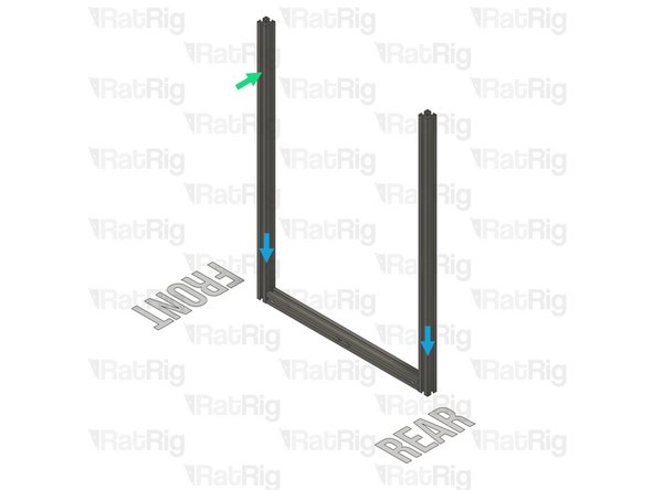
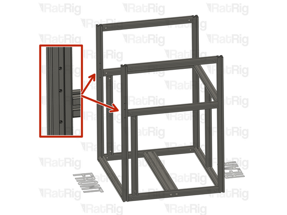
T-Slot 3030 Milled Extrusion - 475mm with Quick Connectors and two M8 holes from step 9
-
Make sure that the counterbores for the M8 holes are oriented as shown
-
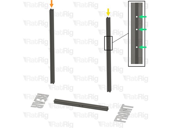
T-Slot 3030 Milled Extrusion - 750mm
-
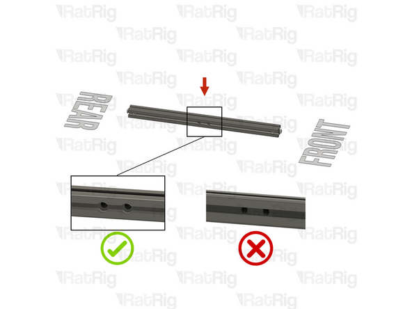
T-Slot 3030 Milled Extrusion - 750mm with three M4 holes
-
Make sure this extrusion is installed as shown. It should be at the front, with the three M4 holes at the top and facing to the side
-
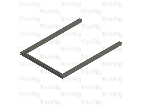
Assemble the extrusions as shown but do not fasten them together yet
-
Be careful when sliding the extrusions into position as you can scratch the black anodising
-
-
-
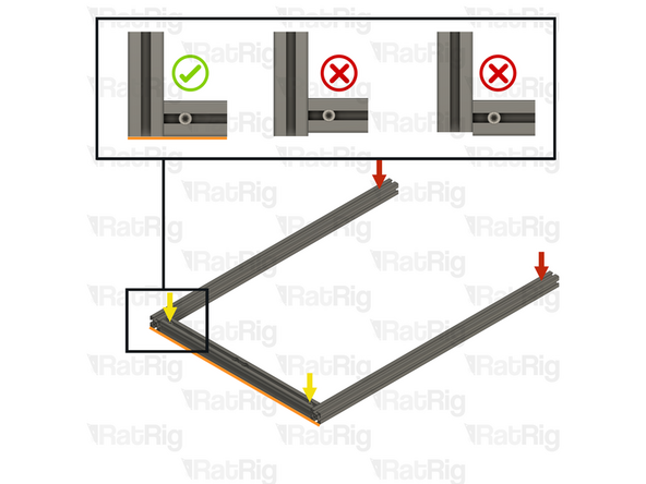
Lay the assembly on a flat surface, this is crucial to ensure a square frame
-
Good surfaces: Poured self-levelled concrete, glass, or a stone countertop
-
Bad surfaces: Carpeted floor, a tile floor, or rough concrete
-
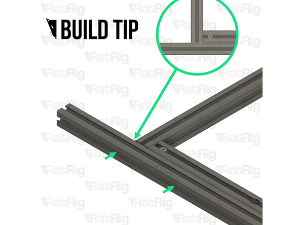
Align the extrusions as shown - making sure the ends are flush
-
Build Tip: You can use a spare 3030 extrusion or an Engineer Square to help align the assembly
-
Fasten the Set Screws in both of the Quick Connectors to secure the extrusions together
-
If the extrusion connection is loose after fully tightening the Set Screw, loosen the Set Screw and check that the Quick Connector T-Nut Pin was properly positioned. The connection will not tighten if the "notch" on the pin is not aligned with the Set Screw
-
-
-
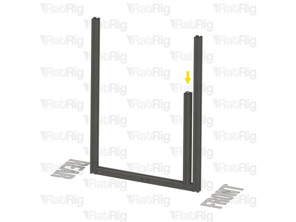
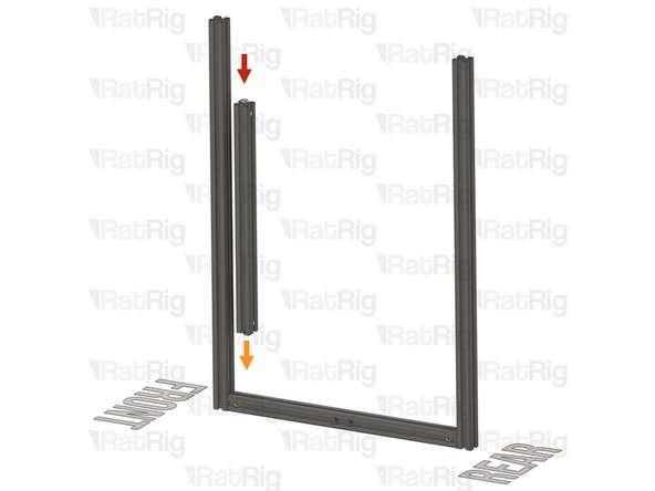
T-Slot 3030 Milled Extrusion - 440mm with Quick Connectors from step 9
-
Align the Quick Connector T-Nut Pin with the bottom extrusion slot
-
Insert the Quick Connector T-Nut Pin into the bottom extrusion slot
-
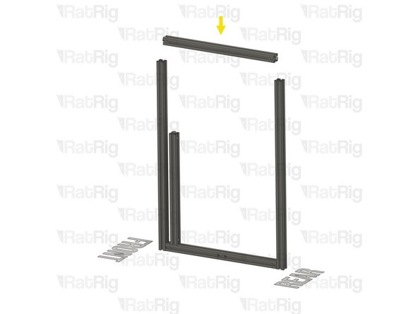
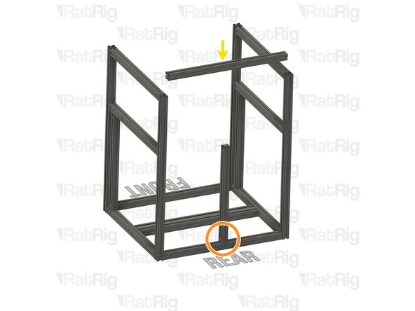
T-Slot 3030 Milled Extrusion - 475mm with Quick Connectors from step 9
-
Insert the extrusion into the side assemblies, making sure the Quick Connector T-Nut pins are aligned with the side extrusion slots
-
Be careful not to scratch the aluminium extrusions when assembling them
-
-
-
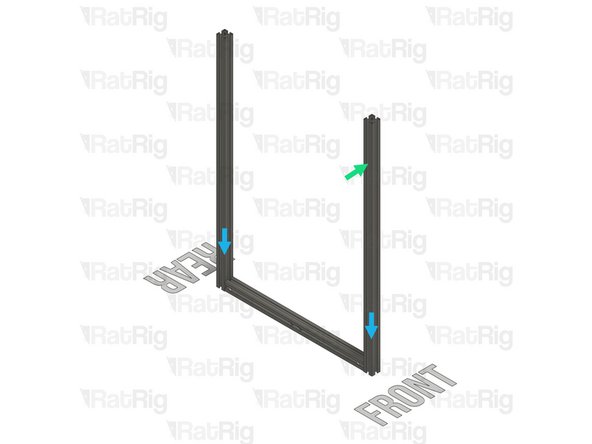
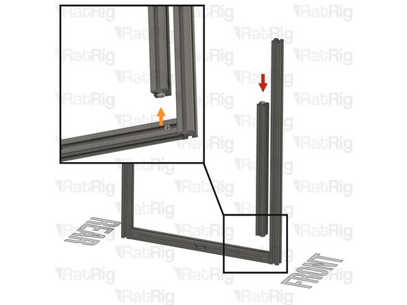
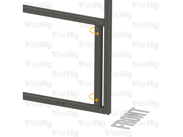
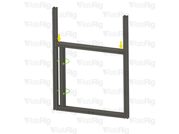
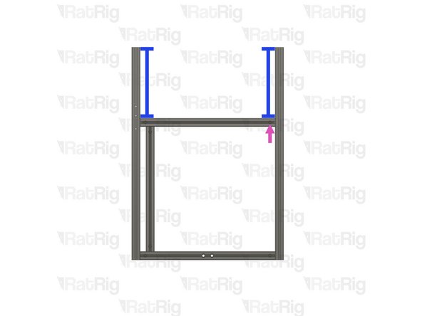
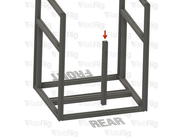
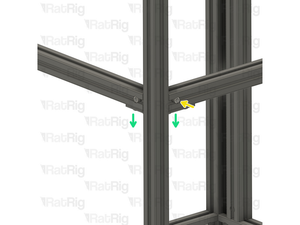
Slide the marked extrusion downwards, making sure the Quick Connector T-Nut Pin on the 440mm extrusion fits inside the extrusion slot
-
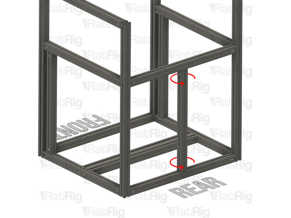
Carefully rotate the marked extrusion 90 degrees so that the Quick Connector Set Screws face outwards as shown
-
Look into the extrusion slots and make sure that both the upper and lower Quick Connector T-Nut Pins have rotated correctly
-
Be careful not to scratch the aluminium extrusions when assembling them
-
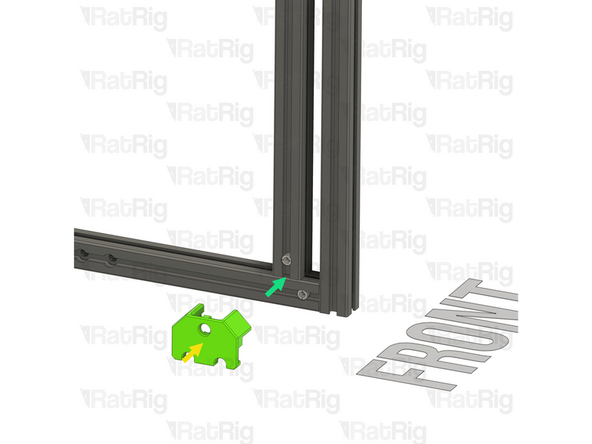
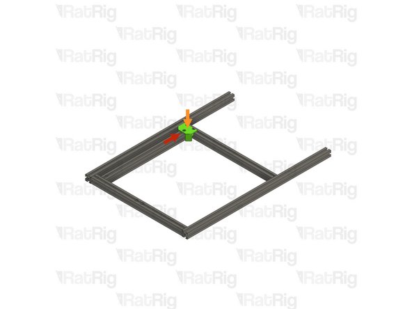
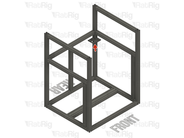
V-Core 4.0 Frame Jig
-
Install the Frame Jig onto the assembly as shown
-
-
-
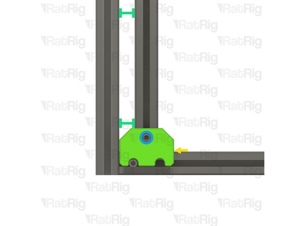
Lay the assembly on a flat surface, this is crucial to ensure a square frame
-
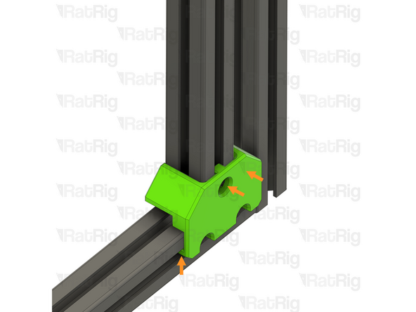
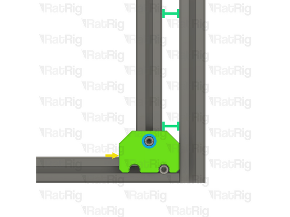
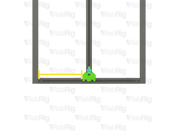
Make sure the Frame Jig is installed completely flush with the extrusion and that the bottom "tabs" are within the extrusion slot
-
Push the Frame Jig to the right to eliminate any space between the Frame Jig and the front extrusion
-
The marked gap should measure 20mm
-
Build Tip: You can use the 2020 V-Slot extrusion to verify the gap but be careful not to scratch the aluminium extrusions
-
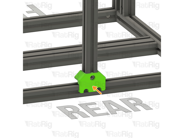
Fully tighten the marked Set Screw to secure the extrusions together
-
If the extrusion connection is loose after fully tightening the Set Screw, loosen the Set Screw and check that the Quick Connector T-Nut Pin was properly positioned. The connection will not tighten if the "notch" on the pin is not aligned with the Set Screw
-
-
-
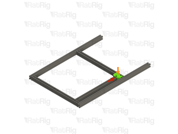
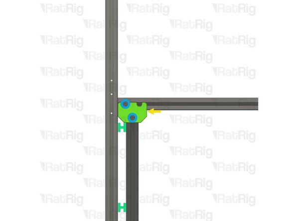
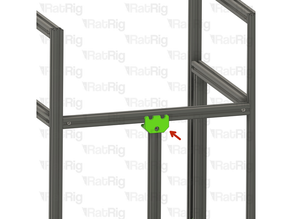
Move the Frame Jig to the marked position
-
Make sure the Frame Jig is installed completely flush with the extrusion and that the bottom "tabs" are within the extrusion slot
-
Push the Frame Jig to the right to eliminate any space between the Frame Jig and the front extrusion
-
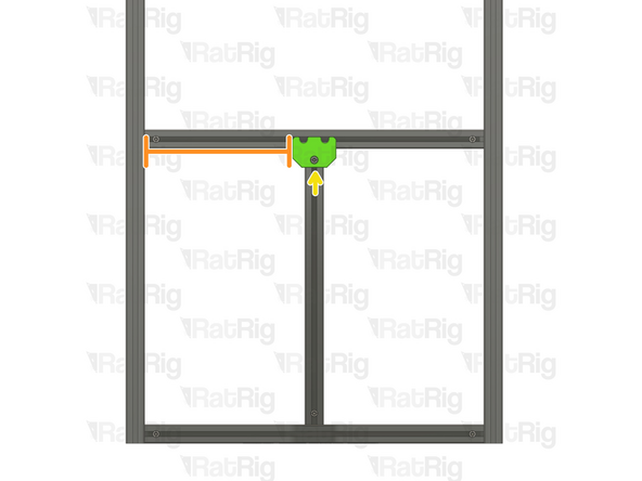
The marked gap should measure 20mm
-
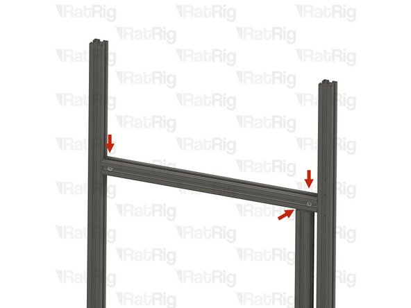
Fully tighten both of the marked Set Screws to secure the extrusions together
-
Double check that the marked distance is 250mm. This measurement is the same for all V-Core 4.0 sizes
-
Fully tighten the marked Set Screw to secure the extrusions together
-
If any of the extrusion connections are loose after fully tightening the Set Screws, loosen the Set Screw on the loose joint and check that the Quick Connector T-Nut Pin was properly positioned. The connection will not tighten if the "notch" on the pin is not aligned with the Set Screw
-
-
-
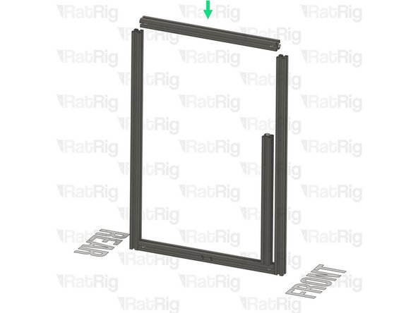
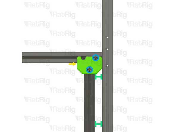
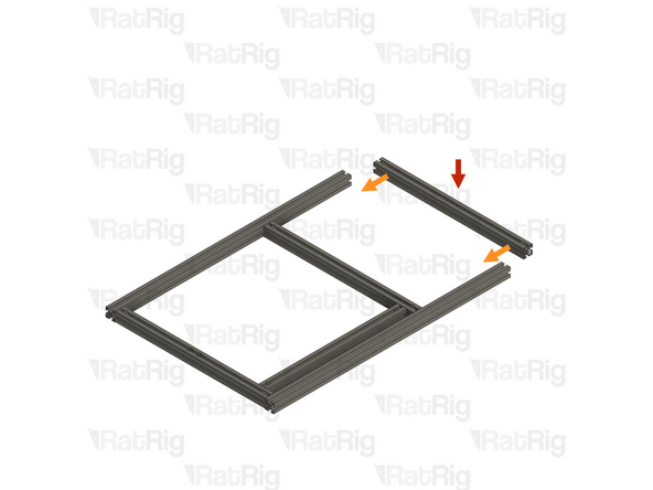
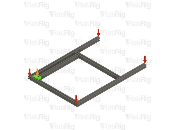
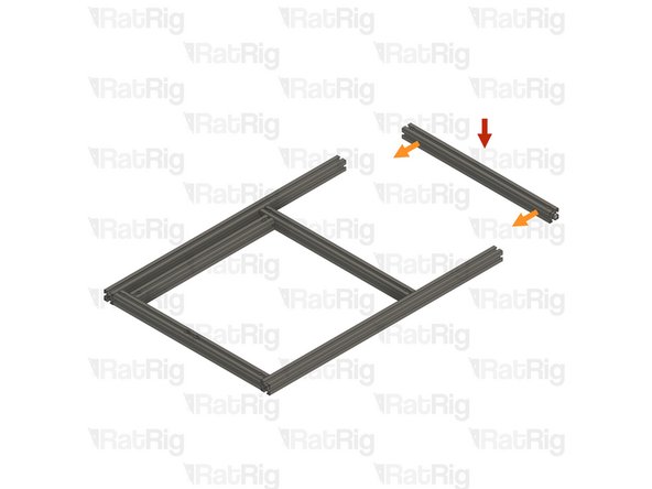
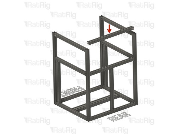
T-Slot 3030 Milled Extrusion - 475mm with Quick Connectors from step 9
-
Insert the extrusion into the side assemblies, making sure the Quick Connector T-Nut pins are aligned with the side extrusion slots
-
Be careful not to scratch the aluminium extrusions when assembling them
-
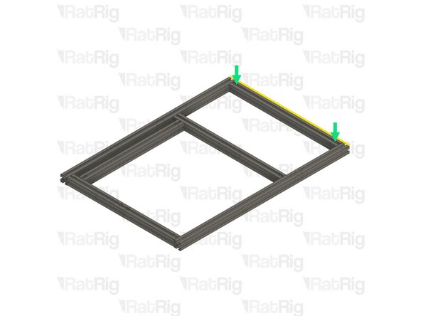
Align the extrusions as shown - making sure the ends are flush
-
Refer to step 12 for instructions on how to correctly align the extrusions
-
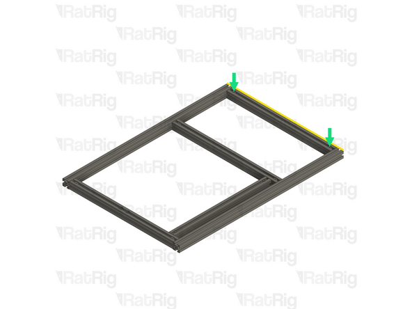
Fully tighten both of the marked Set Screws to secure the extrusions together
-
If any of the extrusion connections are loose after fully tightening the Set Screws, loosen the Set Screw on the loose joint and check that the Quick Connector T-Nut Pin was properly positioned. The connection will not tighten if the "notch" on the pin is not aligned with the Set Screw
-
-
-
-
T-Slot 3030 Milled Extrusion - 475mm with Quick Connectors and two M8 holes from step 9
-
Make sure that the counterbores for the M8 holes are oriented as shown
-
T-Slot 3030 Milled Extrusion - 750mm with three M4 holes
-
T-Slot 3030 Milled Extrusion - 750mm
-
Make sure this extrusion is installed as shown. It should be at the front, with the three M4 holes at the top and facing to the side
-
Assemble the extrusions as shown but do not fasten them together yet
-
-
-
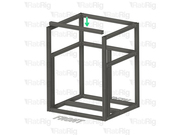
T-Slot 3030 Milled Extrusion - 440mm with Quick Connectors from step 9
-
Align the Quick Connector T-Nut Pin with the bottom extrusion slot and insert it
-
T-Slot 3030 Milled Extrusion - 475mm with Quick Connectors from step 9
-
Insert the extrusion into the side assemblies, making sure the Quick Connector T-Nut pins are aligned with the side extrusion slots
-
Slide the extrusion downwards, making sure the Quick Connector T-Nut Pin on the 440mm extrusion fits inside the extrusion slot
-
Carefully rotate the marked extrusion 90 degrees so that the Quick Connector Set Screws face outwards as shown
-
Look into the extrusion slots and make sure that both the upper and lower Quick Connector T-Nut Pins have rotated correctly
-
Be careful not to scratch the aluminium extrusions when assembling them
-
-
-
Lay the assembly on a flat surface, this is crucial to ensure a square frame
-
Install the Frame Jig onto the assembly as shown
-
Make sure the Frame Jig is installed completely flush with the extrusion and that the bottom "tabs" are within the extrusion slot
-
Push the Frame Jig to the left to eliminate any space between the Frame Jig and the front extrusion
-
The marked gap should measure 20mm
-
Build Tip: You can use the 2020 V-Slot extrusion to verify the gap but be careful not to scratch the aluminium extrusions
-
Fully tighten the marked Set Screw to secure the extrusions together
-
If the extrusion connection is loose after fully tightening the Set Screw, loosen the Set Screw and check that the Quick Connector T-Nut Pin was properly positioned. The connection will not tighten if the "notch" on the pin is not aligned with the Set Screw
-
-
-
Move the Frame Jig to the marked position
-
Make sure the Frame Jig is installed completely flush with the extrusion and that the bottom "tabs" are within the extrusion slot
-
Push the Frame Jig to the left to eliminate any space between the Frame Jig and the front extrusion
-
The marked gap should measure 20mm
-
Fully tighten both of the marked Set Screws to secure the extrusions together
-
Double check that the marked distance is 250mm. This measurement is the same for all V-Core 4.0 sizes
-
Fully tighten the marked Set Screw to secure the extrusions together
-
If any of the extrusion connections are loose after fully tightening the Set Screws, loosen the Set Screw on the loose joint and check that the Quick Connector T-Nut Pin was properly positioned. The connection will not tighten if the "notch" on the pin is not aligned with the Set Screw
-
-
-
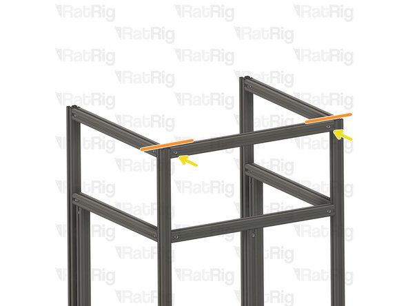
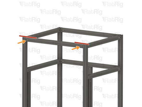
T-Slot 3030 Milled Extrusion - 475mm with Quick Connectors from step 9
-
Insert the extrusion into the side assemblies, making sure the Quick Connector T-Nut pins are aligned with the side extrusion slots
-
Be careful not to scratch the aluminium extrusions when assembling them
-
Align the extrusions as shown - making sure the ends are flush
-
Refer to step 12 for instructions on how to correctly align the extrusions
-
Fully tighten both of the marked Set Screws to secure the extrusions together
-
If any of the extrusion connections are loose after fully tightening the Set Screws, loosen the Set Screw on the loose joint and check that the Quick Connector T-Nut Pin was properly positioned. The connection will not tighten if the "notch" on the pin is not aligned with the Set Screw
-
-
-
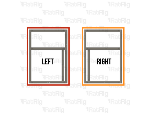
Left Side frame sub-assembly
-
T-Slot 3060 extrusion - 540mm
-
Align the extrusion with the two holes on the side frame sub-assembly bottom extrusion
-
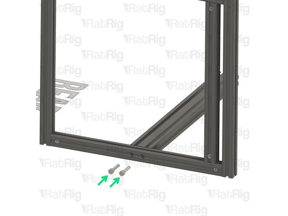
2x M8x40 Cap Head screw
-
Insert them into the sub frame assembly and tighten them to the T-Slot 3060 extrusion - 540mm
-
2x T-Slot 3030 Milled extrusion - 540mm
-
Insert the extrusion on the assembly, making sure the T-nut pins are aligned with the side extrusion slots.
-
When sliding the extrusion to the right place, be careful, and take it slowly so as to not damage the extrusion coating.
-
-
-
Place the assembly on a flat surface, as to ensure all extrusions are correctly aligned.
-
Tighten the quick connectors to secure the extrusions together.
-
Always verify the strength of the connection between the extrusions. If the connection is not strong, loosen the set screw, ensure that the T-nut pin groove is positioned below the set screw, and reconnect the extrusions.
-
-
-
Right Side frame sub-assembly
-
Insert the extrusion on the assembly, making sure the T-nut pins are aligned with the side extrusion slots.
-
When sliding the extrusion to the right place, be careful, and take it slowly so as to not damage the extrusion coating.
-
Align the extrusion with the two holes on the side frame sub-assembly bottom extrusion
-
Insert 2x M8x40 Cap Head screw into the sub frame assembly and tighten to the T-Slot 3060 extrusion - 540mm
-
Place the assembly on a flat surface, as to ensure all extrusions are correctly aligned.
-
Tighten the quick connectors to secure the extrusions together.
-
Always verify the strength of the connection between the extrusions. If the connection is not strong, loosen the set screw, ensure that the T-nut pin groove is positioned below the set screw, and reconnect the extrusions.
-
-
-
T-Slot 3030 Milled extrusion - 440mm
-
Align the T-nut pin with the bottom extrusion slot
-
Insert the T-nut pin in the bottom extrusion slot.
-
T-Slot 3030 Milled extrusion - 540mm
-
Insert the extrusion on the assembly, making sure the T-nut pins are aligned with the side extrusion slots.
-
When sliding the extrusion to the right place, be careful, and take it slowly so as to not damage the extrusion coating.
-
-
-
Carefully rotate the T-Slot 3030 Milled extrusion - 440mm 90º so the quick connectors face the side shown in the picture.
-
Insert the frame jig on the assembly, make sure the frame jig is inserted all the way and completely flush with the extrusion
-
Ensure the distance between the frame jig side wall and the frame extrusion is 235mm
-
It should be 285mm for the V-Core 4 400 and 335mm for the V-Core 4 500
-
Tighten the quick connector to secure the extrusions together.
-
Always verify the strength of the connection between the extrusions. If the connection is not strong, loosen the set screw, ensure that the T-nut pin groove is positioned below the set screw, and reconnect the extrusions.
-
-
-
Insert the frame jig on the assembly, make sure the frame jig is inserted all the way and completely flush with the extrusion
-
Ensure the distance between the frame jig side wall and the frame extrusion is 235mm
-
Add 50mm for the V-Core 4 400 and 100mm for the V-Core 4 500
-
Tighten the quick connector to secure the extrusions together.
-
Always verify the strength of the connection between the extrusions. If the connection is not strong, loosen the set screw, ensure that the T-nut pin groove is positioned below the set screw, and reconnect the extrusions.
-
-
-
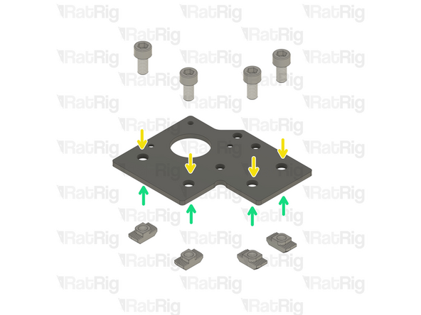
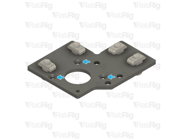
In this step, you will prepare two stepper motor plates with screws and T-nuts, although they will only be used to align the frame.
-
Rat Rig V-Core 4.0 - Motor Plate - Lower Left v1.0
-
Rat Rig V-Core 4.0 - Motor Plate - Lower Right v1.0
-
8x M6x12 Cap Head Screw
-
8x 3030 Drop In T-Nut M6
-
Loosely thread the 3030 T-Nuts onto the M6x12 screws. Do not tighten them at this point.
-
Please notice: The t-nuts should be on the same side as the countersink holes.
-
-
-
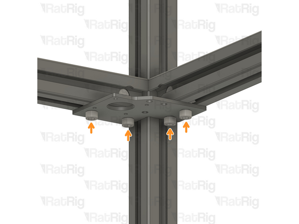
Install the Rat Rig V-Core 4.0 - Motor Plate - Lower Right v1.0 Assembly to the frame as shown
-
Tighten the M6x12 Cap Head Screws to secure the plate and guarantee the extrusions are perfectly aligned.
-
Tighten the quick connector to secure the extrusions together.
-
Always verify the strength of the connection between the extrusions. If the connection is not strong, loosen the set screw, ensure that the T-nut pin groove is positioned below the set screw, and reconnect the extrusions.
-
Remove the Rat Rig V-Core 4.0 - Motor Plate - Lower Right v1.0 Assembly and set it aside, it will be used later in the guide.
-
Repeat the Steps above for the other end of the extrusion, using the Rat Rig V-Core 4.0 - Motor Plate - Lower Left v1.0 Assembly
-
-
-
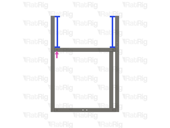
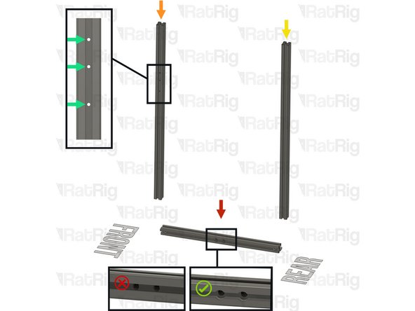
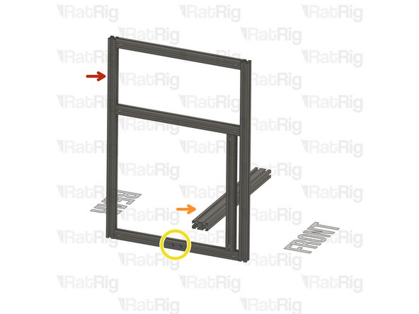
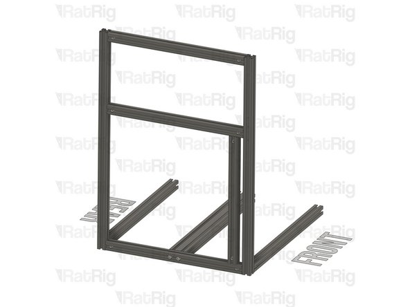
Make sure the front side extrusions have the 3xM3 holes facing the sides. Be aware of the extrusion orientation, the small spacing between the M3 holes must be upwards.
-
-
-
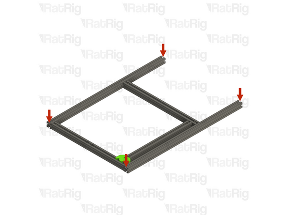
T-Slot 3030 Milled extrusion - 540mm
-
Insert the extrusion on the assembly, making sure the T-nut pins are aligned with the side extrusion slots.
-
Ensure the two extrusions are perfectly aligned
-
Refer to Step 10 on how to accurately align the extrusions.
-
Tighten the quick connectors to secure the extrusions together.
-
Always verify the strength of the connection between the extrusions. If the connection is not strong, loosen the set screw, ensure that the T-nut pin groove is positioned below the set screw, and reconnect the extrusions.
-
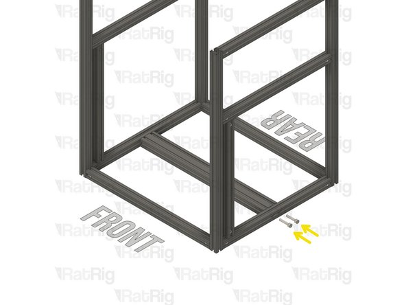
T-Slot 3030 Milled extrusion - 540mm
-
Insert the extrusion on the assembly, making sure the T-nut pins are aligned with the side extrusion slots.
-
-
-
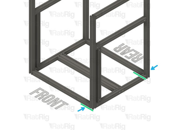
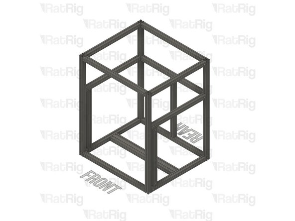
Ensure the two extrusions are perfectly aligned
-
Refer to Step 10 on how to accurately align the extrusions.
-
Tighten the quick connectors to secure the extrusions together.
-
Always verify the strength of the connection between the extrusions. If the connection is not strong, loosen the set screw, ensure that the T-nut pin groove is positioned below the set screw, and reconnect the extrusions.
-
-
-
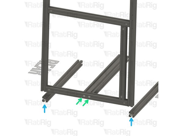
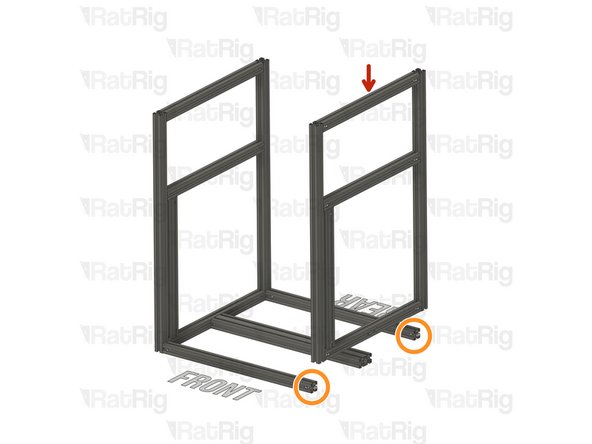
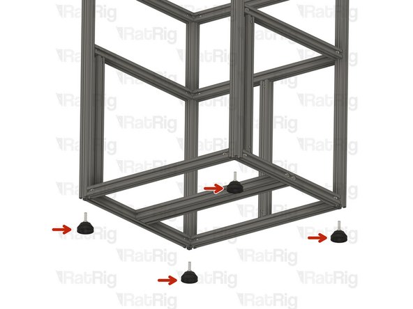
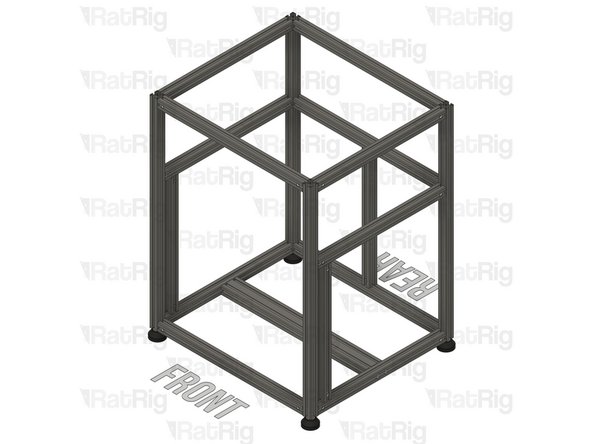
4 x V-Core 4 rubber feet
-
Tighten the four V-Core 4 rubber feet to the frame assembly
-
-
-
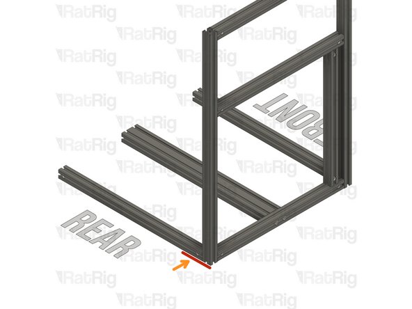
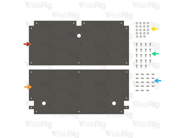
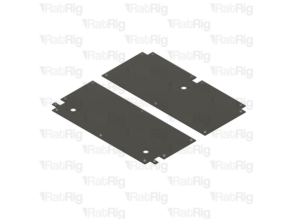
1x Rear base plate
-
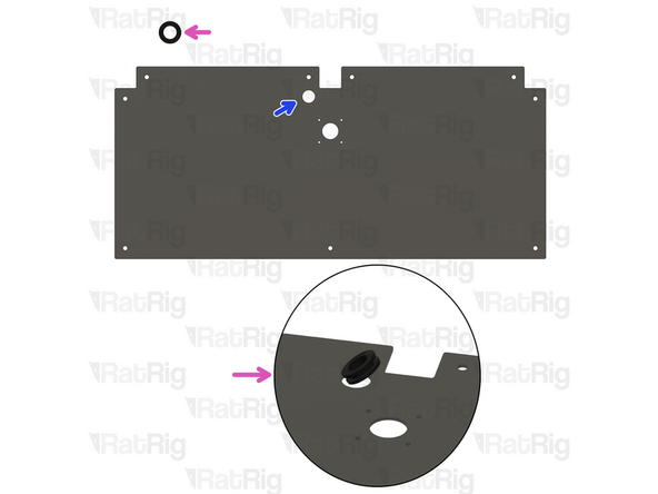
The rear plate has been recently updated. If you purchased your kit recently, your rear plate may feature a new hole for the Z stepper motor cable management. Refer to the second picture for more details.
-
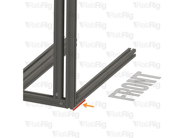
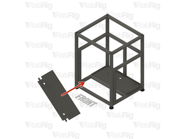
1x Front base plate
-
19x M6 Washer
-
19x M6x12 Cap Head Screws
-
19x 3030 M6 Drop in T-Nut
-
Updated rear base plate with Z cable passthrough.
-
Rubber grommet. Insert the grommet in the designated hole.
-
-
-
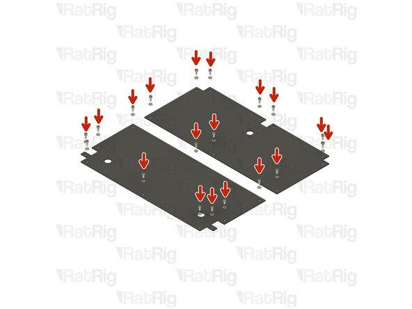
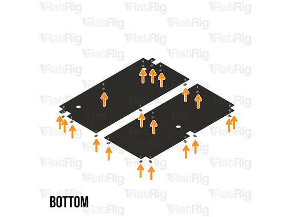
Inset a M6x12 Cap Head Screw + M6 washer on every 6mm hole on the base plates.
-
Loosely thread the 3030 T-Nuts onto the M6x12 screws. Do not tighten them at this point.
-
-
-
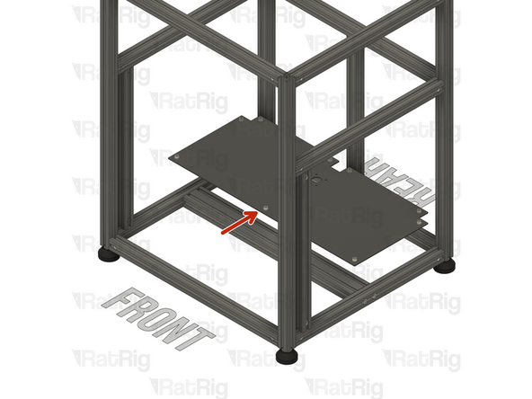
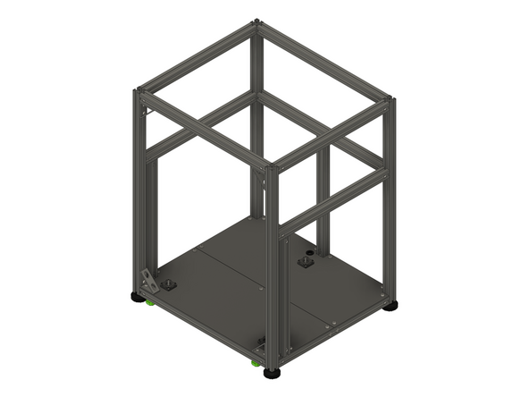
Rear base plate assembly
-
Carefully place it inside the frame. The Z cable passthrough should be on the left side when facing the front of the printer.
-
Ensure the base plate assembly is pushed all the way to the back and aligned with the rear extrusions.
-
When sliding the base plate assembly to the right place, be careful, and take it slowly so as to not damage the extrusion coating.
-
Place the base plate assembly on the bottom of the frame
-
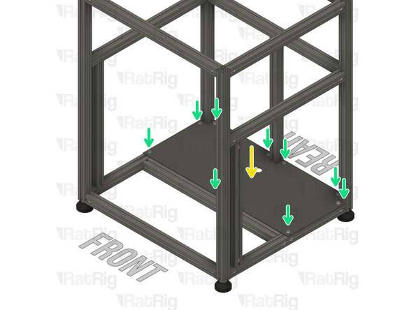
Make sure every 3030 Drop In T-nut aligns with the extrusion slots
-
Tighten the M6x12 Cap Head Screws to secure the base plate assembly to the frame.
-
-
-
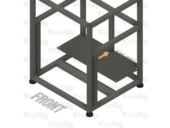
Insert the front base plate inside the frame assembly, at an angle so it can be rotated into place.
-
When sliding the base plate assembly to the right place, be careful, and take it slowly so as to not damage the extrusion coating.
-
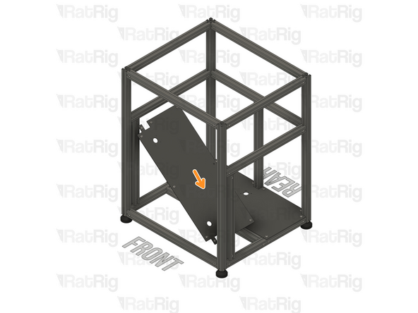
Carefully rotate the front base panel towards the side of the frame, as shown.
-
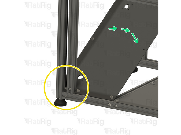
Align the base panel with the extrusions
-
Rotate the front base plate assembly into position.
-
-
-
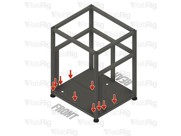
Tighten the M6x12 Cap Head Screws to secure the base plate assembly to the frame.
-
-
-
Continue with the next guide: 02. Z-Axis Assembly
-