-
-
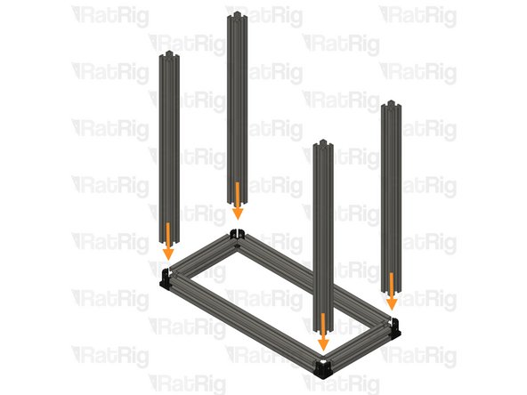
4x T-Slot extrusion 3030 - 160mm
-
4x T-Slot extrusion 3030 - 400mm
-
4x T-Slot extrusion 3030 - 480mm
-
8x Hidden three way corners + 32 M6x8 Set Screws
-
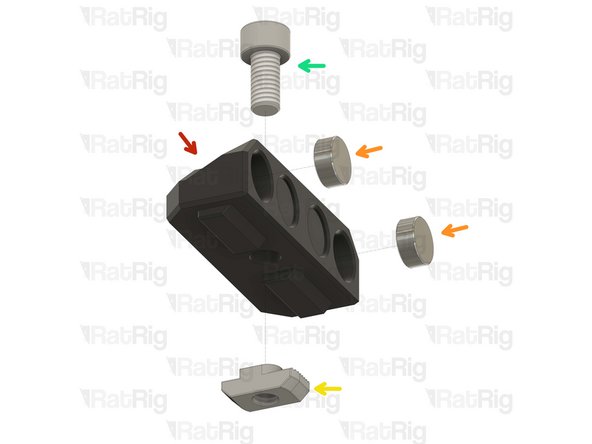
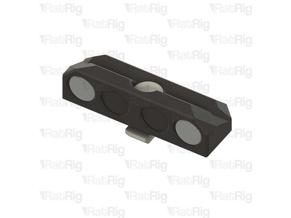
4x vc4_magnet_frame
-
4x M6x12 Cap Head Screw
-
4x 3030 Drop-in T-Nut - M6
-
4x Magnet - Neodymium disc 10x4mm
-
-
-
4x M6x8 Set Screw
-
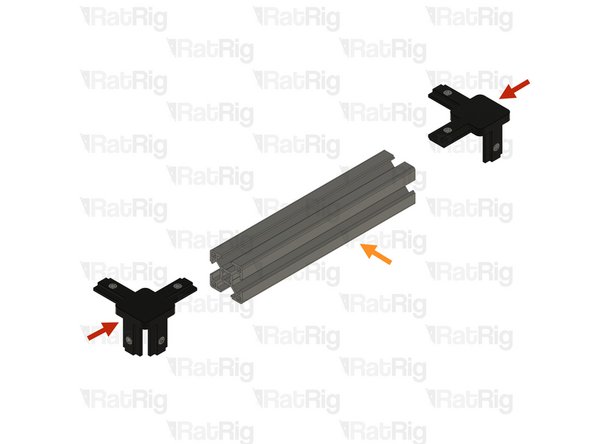
Hidden Three Way Corner
-
Insert the set screws into the part's threads.
-
-
-
2x Hidden three-way corner assembly from the last step
-
1x T-Slot extrusion 3030 - 160mm
-
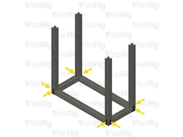
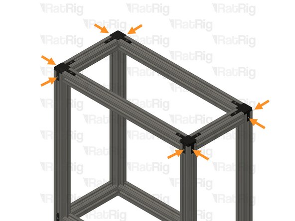
Ensure the extrusions are flush and square with the hidden three way corner assembly before and after tightening the screws.
-
Tighten the M6x8 set screws.
-
Be careful while tightening the set screws, extreme force may break the three way hidden corner.
-
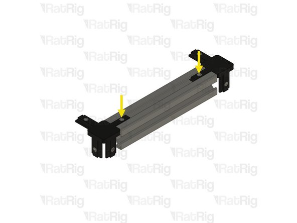
Prepare two assemblies
-
2x T-Slot extrusion 3030 - 400mm
-
Assemble the parts as shown.
-
-
-
Tighten the M6x8 set screws.
-
Be careful while tightening the set screws, extreme force may break the three way hidden corner.
-
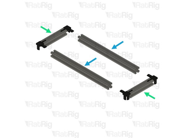
4x T-Slot extrusion 3030 - 448mm
-
Insert the T-slot Exstrusions in the three way hidden corner as shown.
-
Tighten the M6x8 set screws.
-
Ensure the extrusions are flush and square with the hidden three way corner assembly before and after tightening the screws.
-
Be careful while tightening the set screws, extreme force may break the three way hidden corner.
-
-
-
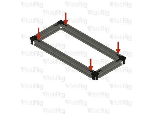
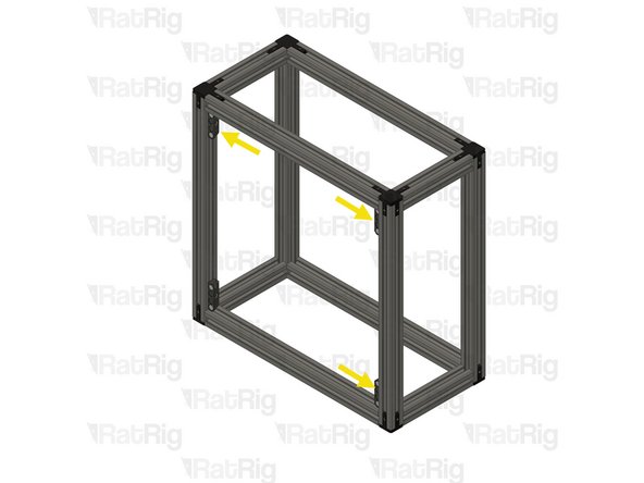
Fram assembly from Step 2
-
Insert the T-slot Exstrusions in the three way hidden corner as shown.
-
Tighten the M6x8 set screws.
-
Ensure the extrusions are flush and square with the hidden three way corner assembly before and after tightening the screws.
-
Be careful while tightening the set screws, extreme force may break the three way hidden corner.
-
-
-
vc4_magnet_frame
-
Magnet - Neodymium disc 10x4mm
-
3030 Drop-in T-Nut - M6
-
M6x12 Cap Head Screw
-
Loosely thread the 3030 T-Nuts onto the M6x12 screws. Do not tighten them at this point.
-
Please verify the magnet polarity in relation to the magnets on the door panel. If the polarity is inverted, the magnets will repel each other instead of attracting.
-
Prepare 4 assemblies
-
-
-
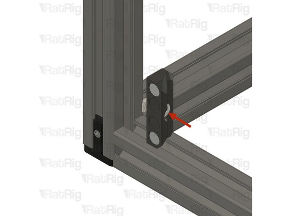
Position the magnet mount assembly as shown.
-
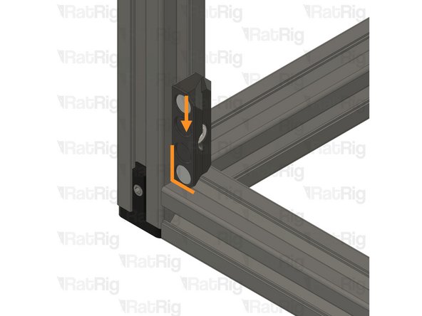
Push it down so it sits flush with both extrusions.
-
Position the remaining magnet mount assemblies as shown.
-
-
-
2x ucee_grommet_45mm
-
2x ucee_grommet_80mm
-
ucee_grommet_90mm
-
ucee_grommet_107mm
-
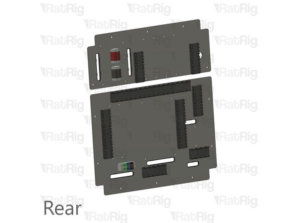
Rat Rig Universal CNC Electronics Enclosure - Components Upper
-
Rat Rig Universal CNC Electronics Enclosure - Components Lower
-
Insert the grommets into place, they should click in place.
-
-
-
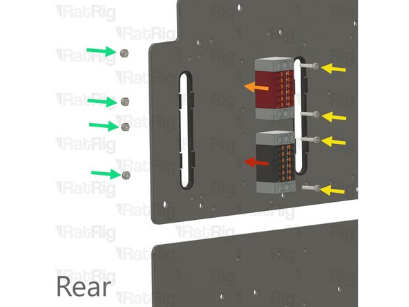
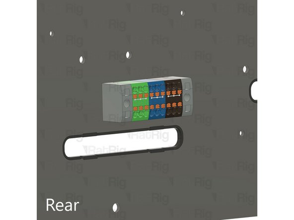
GND PTFix block
-
+24V PTFix block
-
4x M2.5 Cap Head Screw
-
4x M2.5 Nylon Locking Nut
-
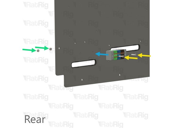
Mains volatage PTFix block
-
2x M2.5 Cap Head Screw
-
2x M2.5 Nylon Locking Nut
-
Using the Screws and Nylon Locking Nuts secure the PTFix blocks to the rear of the electronics panels.
-
-
-
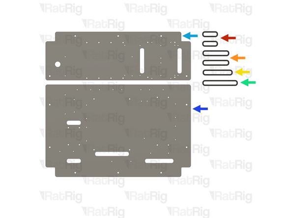
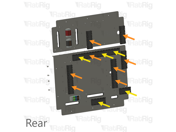
(26x) M3x6 Cap Head Screw + M3 Washer
-
Insert a screw and washer from the front of the plate in every marked hole
-
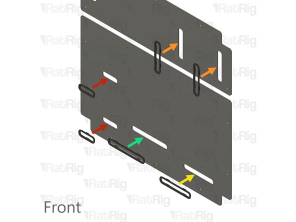
Secure the eight vc4_cable_guide_4 assembly using M3x6 screws and heat inserts in the back at the designated locations.
-
Secure the five vc4_cable_guide_5 assembly using M3x6 screws and heat inserts in the back at the designated locations.
-
-
-
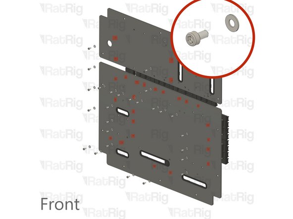
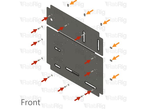
12x M5x12 Cap Head Screws
-
12x 3030 Drop-in T-Nut - M5
-
Insert a Screw and T-nut on every marked hole
-
-
-
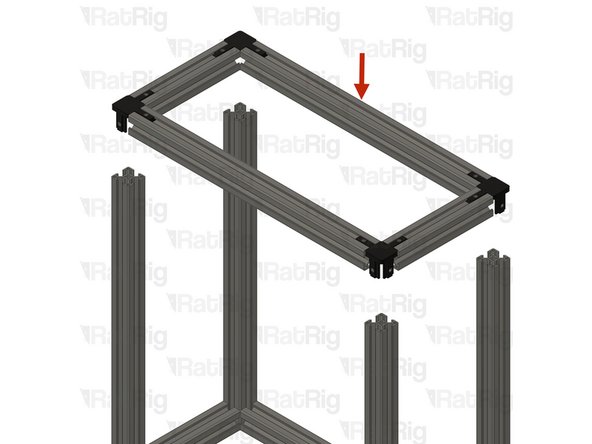
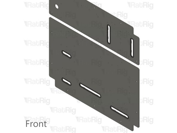
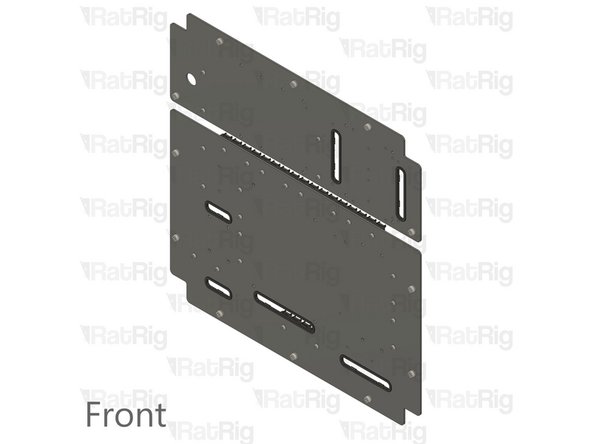
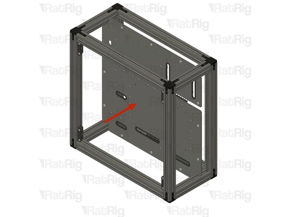
Insert the panels into the frame as shown.
-
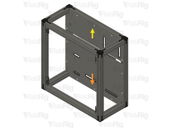
Ensure the lower panel is aligned flush with the bottom extrusion, then securely tighten the screws.
-
Ensure the top panel is aligned flush with the top extrusion, then securely tighten the screws.
-