
-
-
Repeat this step for both XY Plates.
-
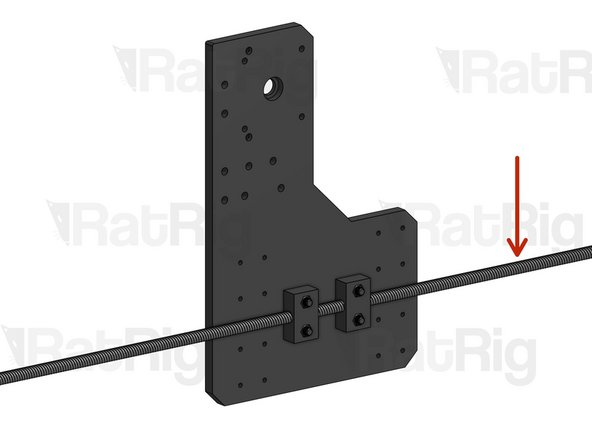
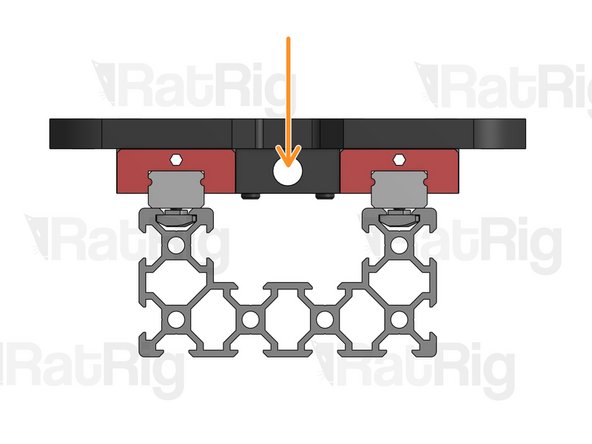
XY Plate
-
Take note of the large counterbore on the plates. Nut Blocks should be mounted on this side of each plate (the side where the hole has a larger diameter).
-
Nut Block
-
Cap Head Screw M5x25mm
-
Washer M5 Black
-
Hex Locking Nut M5
-
Do not fasten the Nut Blocks all the way down just yet. You will need to adjust their position in a moment.
-
-
-
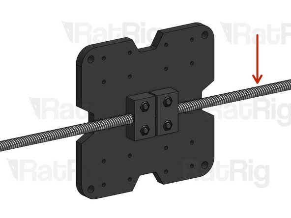
Repeat this step for both XZ Plates.
-
XZ Plate
-
Take note of the counterbores on the plates. Nut Blocks should be mounted on this side of each plate (the side where the hole has a smaller diameter).
-
Take note of the orientation of the Nut Blocks. They should be oriented in a way that gives you room to move them closer or farther apart from each other.
-
Nut Block
-
Cap Head Screw M5x16mm
-
Hex Locking Nut M5
-
Do not fasten the Nut Blocks all the way down just yet. You will need to adjust their position in a moment.
-
-
-
Repeat this step for the 2 XY plates and the 2 XZ plates that were set up with Nut Blocks on the previous steps.
-
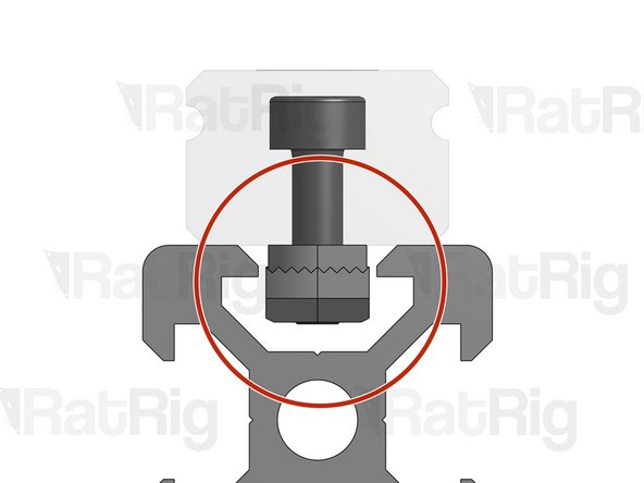
Lead Screw
-
Fasten a lead screw (at this point it doesn't matter which one, but you may find the smallest one to be more practical) through both nut blocks.
-
Press one of Nut Blocks towards the other one, making sure it's completely perpendicular to the Lead Screw, and tighten it down.
-
Apply slight pressure to the other Nut Block towards the first one and tighten it down.
-
If you performed the previous step correctly, there should be no slack if you try to push or pull the lead screw. If there is slack, you need to repeat the previous step while applying a bit more pressure on the Nut Block. You don't want to overdo this, though, or you may create unnecessary friction that will increase wear on the block.
-
Once all slack is removed, unfasten your lead screw, you will add it to the build later on.
-
-
-
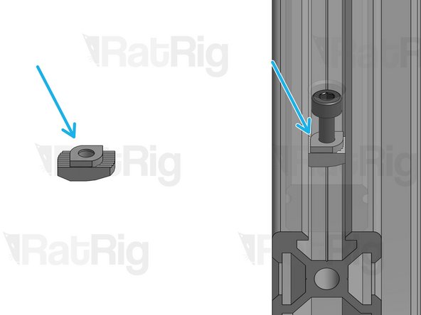
Drop-in T-Nuts
-
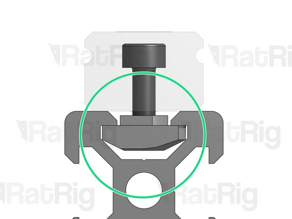
CORRECT USE: When a bolt is screwed through a plate/rail/connector and into a Drop-in T-Nut, the Nut rotates inside the slot as it rises, until it eventually grabs the inside of the profile, in a position perpendicular to the slot. In this position, the bolt is securely fastened.
-
INCORRECT USE: This picture shows an insecurely tightened bolt. As you can see, the Drop-in T-Nut is fully fastened but in a position that is NOT perpendicular to the slot. If this happens, loosen the bolt and re-tighten.
-
To make the assembly process easier, this guide will often ask you to mount Drop-in T-Nuts on screws before mounting them on a profile slot. When you do this, ensure you don't over-tighten the screws into the T-Nuts, otherwise they won't have room to rotate inside the slot, creating the problem described above.
-
-
-
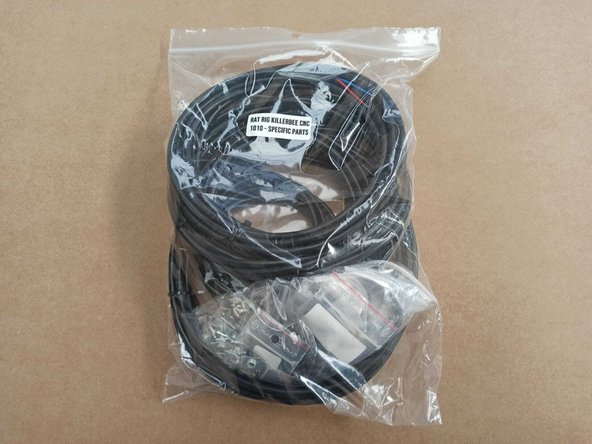
HEADS-UP: Your kit includes a bag labeled "Specific parts". You will need this bag for the next steps.
-
-
-
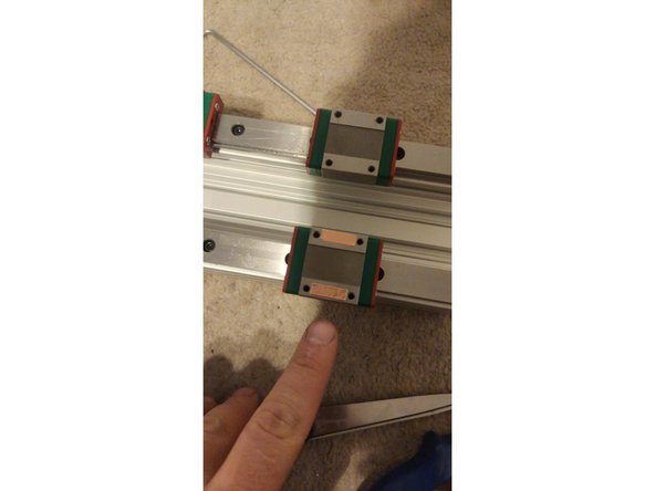
Repeat this step for all Linear Rails included in your kit. Learn more about Linear Rail initial cleanup, troubleshooting and maintenance here. Linear rails give you unmatched precision and reliability, but you need to take proper care of them.
-
Linear Rail carriages are filled with ball bearings. Avoid removing the carriages from the rails so you don't risk losing some of the bearings.
-
Linear Rails ship with plastic caps on the holes at each end. You may choose to keep them in place until you finish your build, to prevent the carriages from falling off the rail during assembly. If you do this, you will forego having screws on these holes, but this is not critical to the performance of your machine.
-
After you finish assembly, you should remove the caps to have access to the full range of movement of the machine.
-
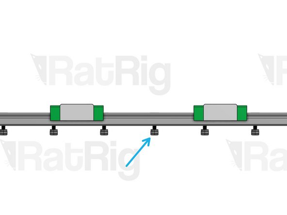
Linear Rail
-
Cap Head Screw M3x10mm
-
Drop-in T-Nut M3
-
Do not tighten the T-Nuts. Screw them in just enough so they don't fall.
-
-
-
Match each pair of Linear Rails with a C-Beam Profile of the same length. Fit the loose T-Nuts hanging from the rails inside the C-Beam slots.
-
Do not tighten the screws yet!
-
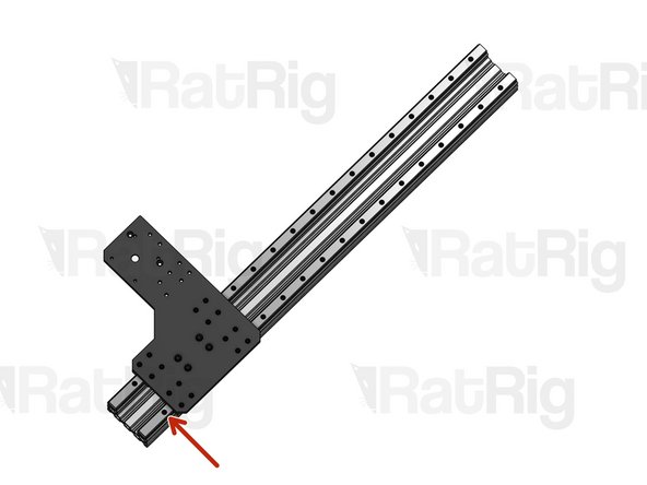
C-Beam Profile
-
-
-
Correct alignment of Linear rails is essential for optimal machine performance. Incorrect alignment may damage your machine. Read instructions carefully to avoid mistakes.
-
Repeat this step for ONE of the Linear Rails mounted on each C-Beam profile. The other Linear Rail should be left loose for now.
-
Place one MGN15 Alignment tool at each end of the Linear Rail.
-
The Linear rails are 2mm shorter than the profile where they sit. Center them so you leave a 1mm gap on each side.
-
Pressing down on the alignment tool, tighten the first screw on the Linear Rail.
-
Pressing down on the alignment tool on the opposite end, tighten the last screw on the Linear Rail.
-
Tighten down all screws in-between.
-
-
-
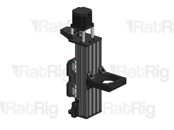
Since there are multiple KillerBee sizes, the guide won't mention lengths. Identify the C-Beam Profiles meant for each machine axis in the following way: Z C-Beam is the shortest one, there's only one X C-Beam, and there are 2 Y C-Beams. Of course, if your machine has the same size on X and Y you will have 3 C-Beams of the same length.
-
Pair each of the Y axis C-Beam profiles with one of the XY Plates.
-
Pair one of the XZ Plates with the Z axis C-Beam profile.
-
Pair the other XZ Plate with the X axis C-Beam profile.
-
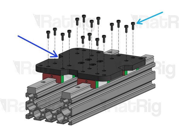
Cap Head M3x12mm (for XY Plates)
-
Washer M3 Black
-
Cap Head M3x8mm (for XZ Plates)
-
Make sure the Nut Blocks on each plate are facing inwards, with the holes aligned with the length of the profile. As long as this is the case, you don't need to worry about the orientation of the plates.
-
-
-
Repeat this step for all C-Beam profiles previously set-up.
-
Move the carriage to one end of the C-Beam, until it is right next to the first loose Linear Rail screw. Tighten it down.
-
Move the carriage to the opposite end of the C-Beam, until it is right next to the last loose linear Rail Screw. Tighten it down.
-
Tighten down all loose screws in between.
-
-
-
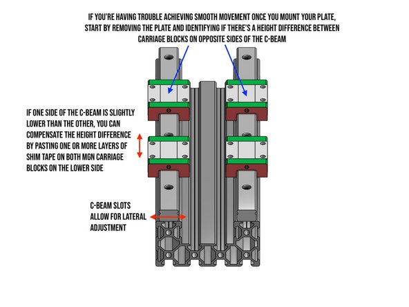
This step is only necessary if you weren't able to achieve smooth carriage movement by following the previous steps.
-
Start by identifying if there's a height difference between carriage blocks on opposite sides of the C-Beam. If one side is lower, you will need to equalize the height by placing one or more layers of shim tape on that side. The shim tape will be sandwiched between the carriage block and the plate.
-
You will find 40cm of 0.04mm Shim Tape included in your kit. Use one or more layers of this tape to equalize the height.
-


Cancel: I did not complete this guide.
6 other people completed this guide.
