
-
-
Z Top Plate
-
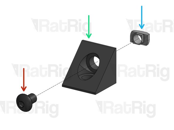
Cap Head Screw M5x60mm
-
Drag chain support Front (printed part)
-
Drag chain support Back (printed part)
-
40mm Spacer
-
Cap Head Screw M5x20mm
-
Hex Locking Nut M5
-
Do not overtighten any of the screws shown in this step.
-
-
-
Low Profile Screw M5x12mm
-
Z Axis C-Beam
-
Bottom Z Plate. Do not fasten all the way down yet, you will need some room for adjustment.
-
Carefully align the Top Z Plate with the corners of the C-Beam before tightening down the screws.
-
-
-
Flexible couplings allow you to connect 2 rods with different diameters while providing some flexibility at the joint.
-
Smaller diameter rod is inserted here
-
Larger diameter rod is inserted here
-
These larger screws act like a clamp on the entire coupling. Tighten these first.
-
These set screws press directly against the tip of each rod, locking it in place.
-
-
-
Flexible Coupling 1/4''x8mm
-
Spacer 40mm
-
Nema 23 Motor
-
Cap Head Screw M5x50mm
-
-
-
Lead Screw 281mm
-
688ZZ Ball Bearing
-
Precision Shim 12x8x1mm
-
Lock Collar 8mm
-
Attach the 8mm end of the flexible coupling to the lead screw. On the coupling, tighten the clamping screws first, and the set screw afterwards.
-
Fully tighten the screws on the Bottom Z Plate, which you left slightly loose on step 2.
-
Press the Lock Collars against the inner face of each Z Plate, and tighten their Set Screw, to lock them in position.
-
-
-
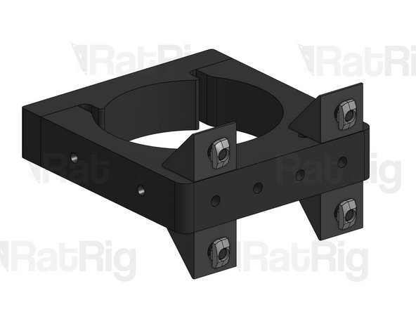
Repeat this step for 4 Angle Corners
-
Button Head Screw M5x8mm
-
Angle Corner
-
Drop-in T-Nut
-
Slightly screw the T-Nut in position, but don't tighten yet.
-
-
-
Spindle Mount Front Part
-
Spindle Mount Back Part
-
Button Head Screw M5x20mm
-
Button Head Screw M5x10mm
-
-
-
Fit the loose Drop-in T-Nuts inside the C-Beam slots. Place the mount roughly at half the C-Beam length.
-
Tighten down the screws to lock the mount in place.
-
-
-
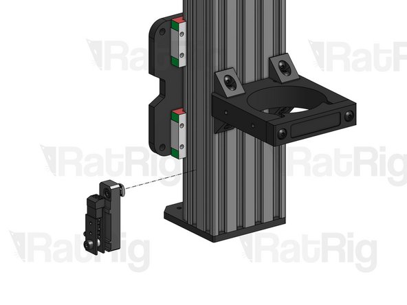
Cap Head Screw M5x20mm
-
Xtension Limit Switch Small Plate
-
Xtension Limit Switch Nylon Spacer
-
Xtension Limit Switch
-
Z Limit Switch mount (printed part)
-
Hex Locking Nut M5
-
Cap Head Screw M5x8mm
-
Drop-in T-Nut M5. Set in position, but don't tighten.
-
-
-
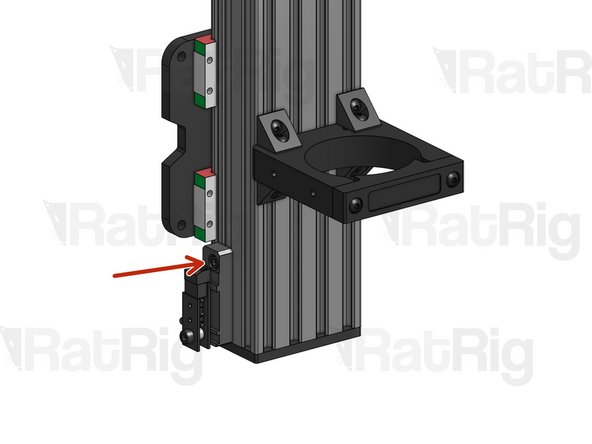
Fit the Drop-in T-Nut inside the C-Beam slot and tighten the screw.
-


Cancel: I did not complete this guide.
6 other people completed this guide.
