
Introduction
This is a step-by-step guide to convert the Z axis of a V-Core Pro 1.2 into the Z axis of a V-Core Pro 1.3.
The X & Y axis of v1.2 and v1.3 are very similar, so upgrading them is an optional step for users coming from v1.2, since it only provides the following:
- Stronger idler housings
- A few extra millimetres of Y range
Upgrading only the Z axis will give you 'almost' the full v1.3 machine without having to disassemble the X & Y axis.
If you want to upgrade the X & Y axis too, at the moment there isn’t a build guide, so you will have to rely on the CAD model to know what goes where. You should upgrade X & Y before upgrading Z.
-
-
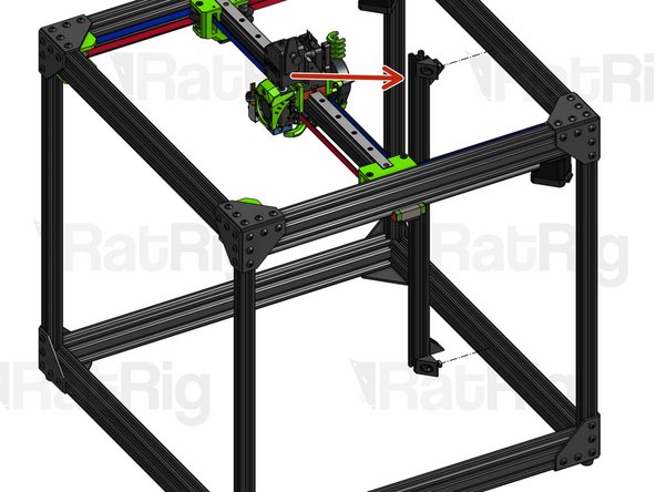
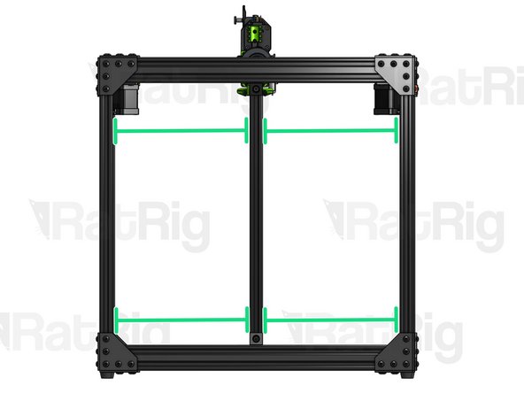
Remove all Z related parts from your current build, including the bed frame (items highlighted in the picture). You will reuse many of these parts in the new build, but in different places.
-
-
-
If you are coming from a V-Core Pro 1.2, your build will include the structural components highlighted in the picture. These components are not part of the official V-Core Pro 1.3 build. However, they are not an obstacle to the build in any way, so you may choose to leave them in place, since they provide additional reinforcement to your frame.
-
For the purposes of this guide, we will assume these components were removed.
-
-
-
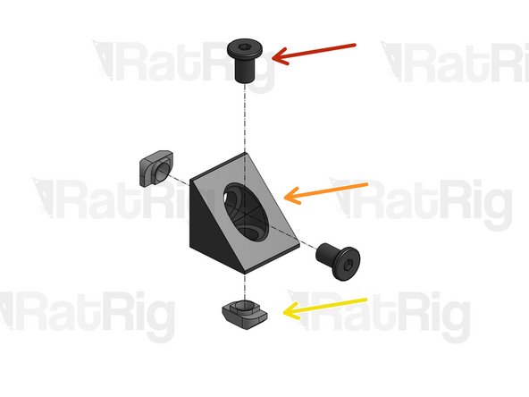
Repeat this step for 4 Angle Corners
-
Low Profile Screw M5x8mm
-
Angle Corner
-
Drop-in T-Nut M5
-
Set T-Nuts in position, but don't tighten them for now.
-
-
-
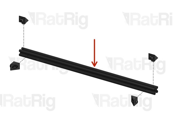
2020 Profile (460mm for Z=300mm)
-
Attach the Angle Corners loosely for now, you will need to adjust their position on the next step.
-
-
-
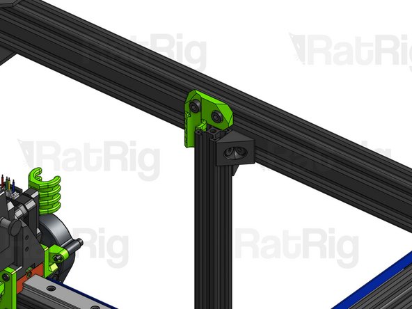
Precision step! Be rigorous or the performance of your machine may be compromised.
-
Carefully place the 2020 profile at the back of the frame, fitting the Drop-in T-Nuts inside the slots.
-
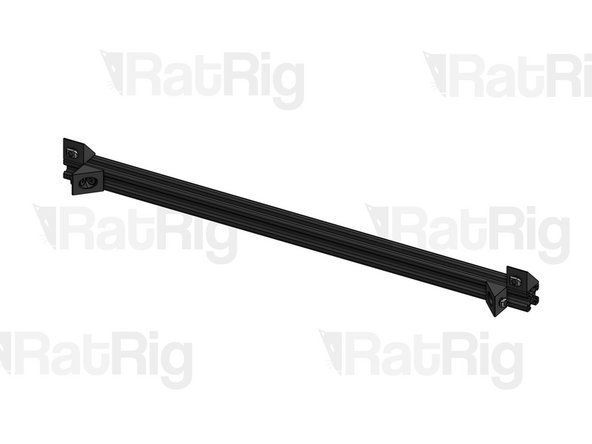
Adjust the lateral position of the profile so it is placed right at the center of the frame. For a 300x300x300 machine, this will be exactly 220mm away from the 2020 profiles on the corners. Measure both at the top and at the bottom, to ensure your profile is not tilted.
-
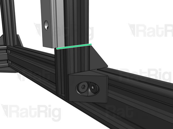
Adjust the vertical position of the profile by ensuring that the top face of this Angle Corner is flush with the horizontal profile, while the bottom face is flush with the end of the vertical profile.
-
-
-
Cap Head Screw M5x8mm
-
Back Cable Relief (printed part)
-
Drop-in T-Nut M5
-
Set T-Nuts in position, but don't tighten them just yet.
-
-
-
Fit the T-Nuts inside the slot and press the corner of the Back Cable Relief against the corner of the Back 2020 profile. Tighten the screws to secure in place.
-
-
-
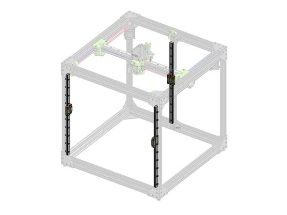
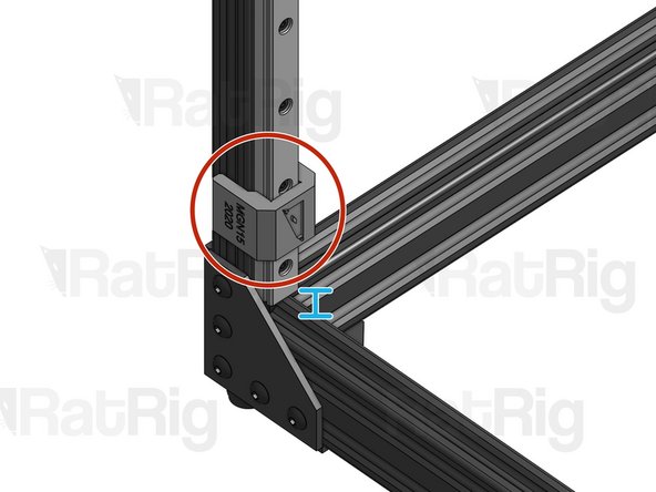
Repeat this step for 3 Linear Rails (on a 300x300x300mm machine they will be 400mm long).
-
If you're coming from v1.1, please reuse one of your existing Z rails on the back of the machine. Even though this rail is 50mm longer than it should be, this will not affect your machine's performance in any way. At the front of the machine, you should use the linear rails provided with your upgrade kit.
-
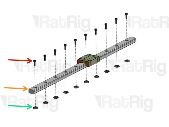
Cap Head Screw M3x10mm
-
Linear Rail MGN15
-
Drop-in T-Nut M3
-
Set T-Nuts in position, but don't tighten them for now.
-
-
-
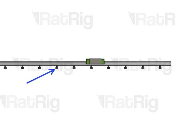
CAUTION: Proper Linear Rail alignment is essential for adequate machine performance. For each of the 3 Linear Rails:
-
Fit the T-Nuts inside the profile slot
-
Place the MGN15 Alignment tool (printed part) at the bottom of the linear rail and tighten the first screw.
-
Move the alignment tool to the top of the linear rail and tighten the last screw
-
Tighten all the screws in between.
-
The build is not too sensitive to the vertical position of the Linear Rails, measurements below are guidelines, they are not critical.
-
The bottom of the front linear rails should be roughly 1cm above the horizontal profile
-
The bottom of the back linear rail should be aligned with the top of the Angle Corner on the opposite side.
-
-
-
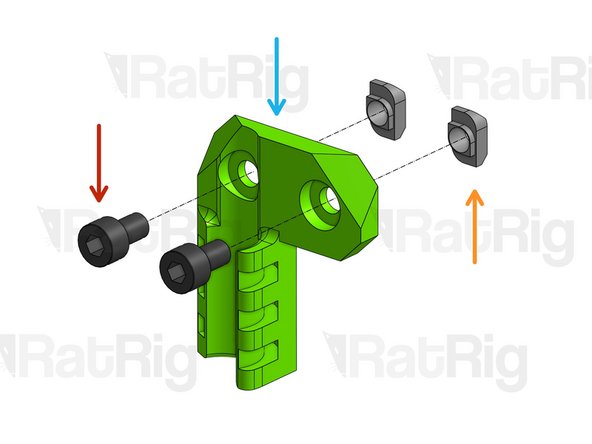
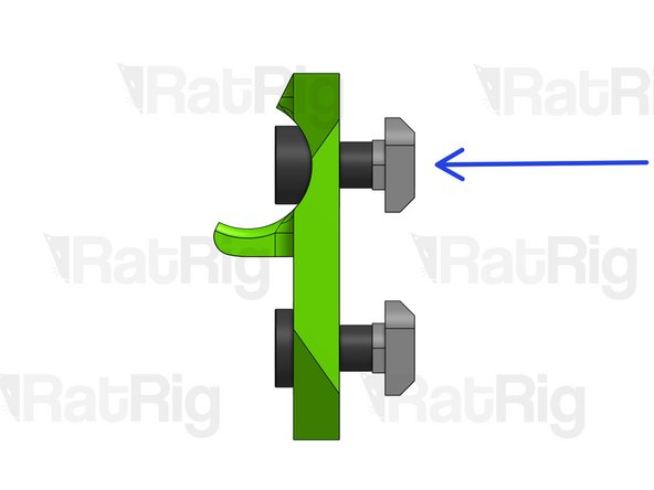
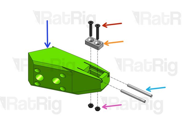
Repeat this step for the 3 Z Arms
-
Z Arm (Printed Part)
-
Countersink Screw M3x20mm
-
Magnet
-
Dowel Pin
-
Hex Locking Nut M3
-
-
-
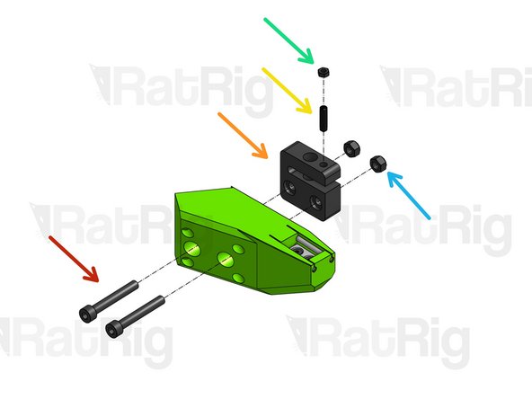
Repeat this step for all 3 Z Arms
-
Cap Head Screw M5x35mm
-
Anti-backlash Nut Block
-
Hex Locking Nut M5
-
Set Screw M5x16mm
-
Thin Hex Nut. Tighten very slightly for now (by hand).
-
-
-
Repeat this step for the Left and Right Z Motor Mounts
-
Cap Head Screw M5x16mm
-
Z Motor Front Left (printed part)
-
Drop-in T-Nut M5. Set in position, but don't tighten it for now.
-
-
-
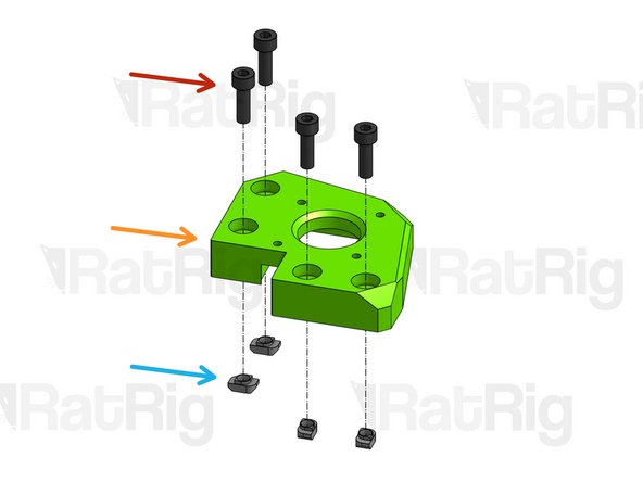
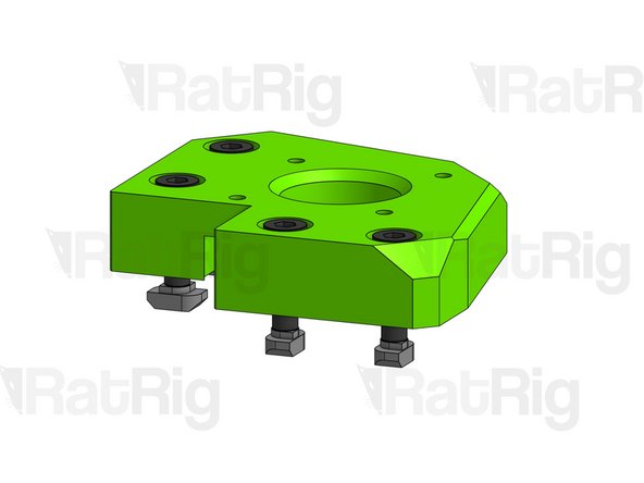
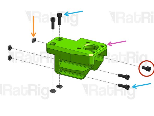
Cap Head Screw M5x10mm
-
Cap Head Screw M5x16mm
-
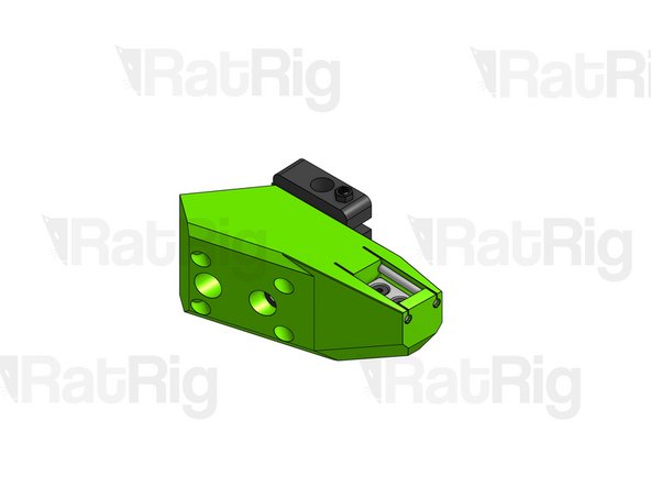
Z Motor Back (printed part)
-
Drop-in T-Nut M5
-
Set T-Nuts in position, but don't tighten them for now.
-
-
-
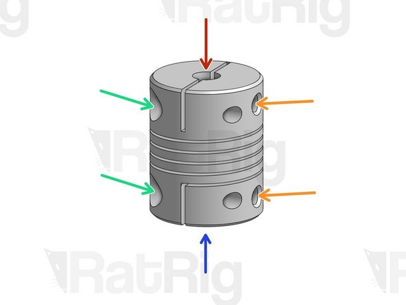
Flexible couplings allow you to connect 2 rods with different diameters while providing some flexibility at the joint.
-
Smaller diameter rod is inserted here
-
Larger diameter rod is inserted here
-
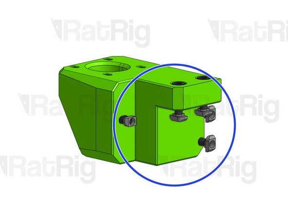
These larger screws act like a clamp on the entire coupling. Tighten these first.
-
These set screws press directly against the tip of each rod, locking it in place.
-
-
-
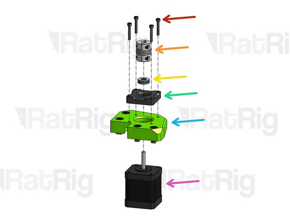
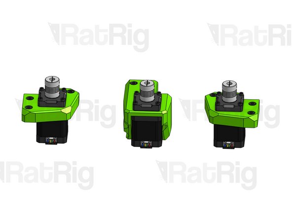
Repeat this step for the 3 Z Motor Mounts. Look at the 3rd image to identify the correct orientation of the motor connectors on each of the mounts.
-
Cap Head Screw M3x20mm
-
Flexible Coupling
-
Thrust Bearing
-
Z Coupler Support
-
Z Motor Mount
-
Nema 17 Stepper Motor
-
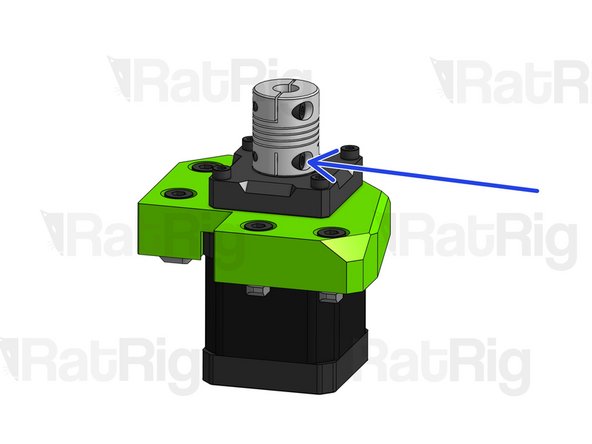
Slightly press down the coupling against the thrust bearing while you tighten down its bottom set screw. Then, tighten down the bottom clamping screw.
-
-
-
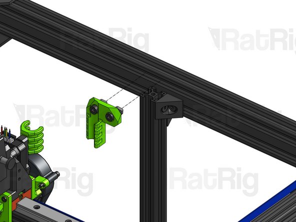
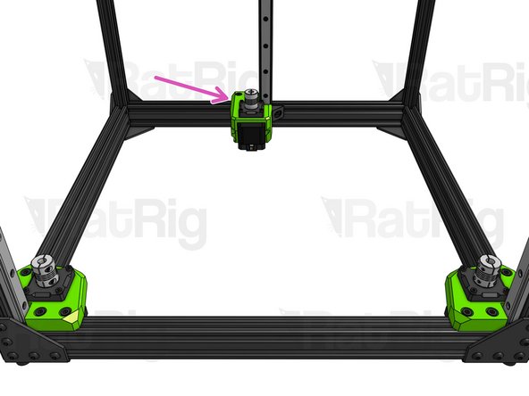
Place the 3 motor mounts on the frame, fitting their T-nuts inside the slots.
-
On the back mount, you will need to remove the 2 T-Nuts for the top slot, to fit the mount into place. You will then need to slide the T-Nuts underneath the printed part.
-
Do not tighten any screws for now!
-
-
-
CAUTION: if you have lead screws of different sizes, make sure you use the short one on the Back Z Arm. Note that this arm is different from the frontal ones.
-
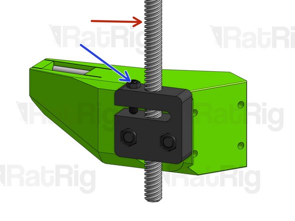
Fasten each of the lead screws through the Anti-backlash nut blocks on the Z Arms, until they are sticking out by 2cm from the opposite end.
-
Tighten the Set Screw on the Anti-backlash nut block until it hits the plastic underneath. Tighten the thin hex nut on top by hand. You may need to tighten this set screw from time to time to calibrate the friction on your lead screw.
-
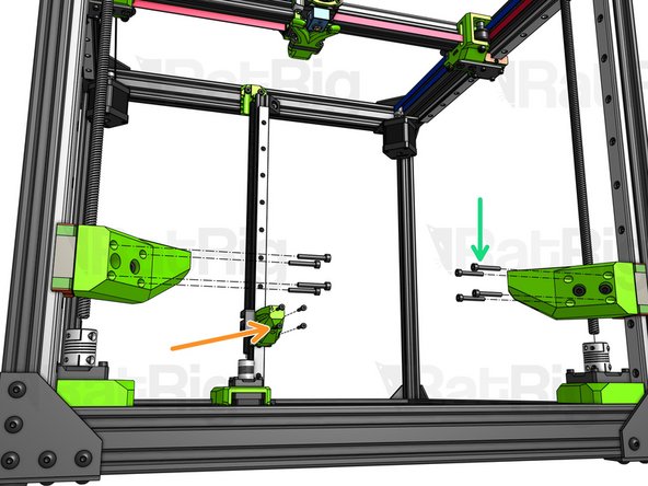
Lift each Linear rail carriage and fasten it to the respective Z Arm with 4 screws.
-
Cap Head Screw M3x20mm (x11)
-
Cap Head Screw M3x10mm (x1)
-
Do not attach the lead screws to the flexible couplings yet!
-
-
-
Repeat this step for all 3 Lead Screws.
-
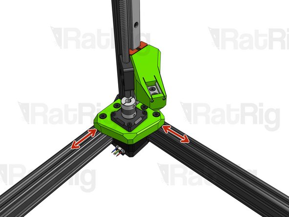
Before they are tightened, the Z Motor mounts have some margin for lateral adjustment. Find the position where the lead screw is in perfect alignment with the hole in the coupling and tighten down the motor mount screws.
-
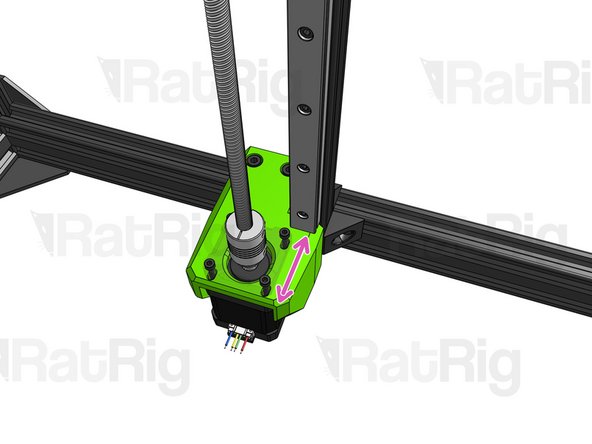
The Back Z Motor Mount has some left-to-right adjustment margin. If you need front-to-back adjustment, you can loosen the M3 screws holding the motor and adjust its position. Find the position where the lead screw is perfectly aligned and tighten down all screws.
-
Let each lead screw drop all the way down into the hole on the coupling. Tighten the top clamping screw on the coupling first.
-
Then, tighten the set screw.
-
-
-
Bed Cable Relief (printed part)
-
Cap Head Screw M3x35mm
-
Hex Locking Nut M3
-


Cancel: I did not complete this guide.
3 other people completed this guide.

One Comment
Thanks for a great guide. Easy to follow and very well described with good picutres.
Alexander Peter - Resolved on Release Reply