
Video Overview
-
-
z_motor_cage printed part
-
4x M6x12 Cap Head Screw
-
4x 3030 Drop-in T-Nut - M6
-
-
-
z_motor_cage printed part
-
2x M6x12 Cap Head Screw
-
2x 3030 Drop-in T-Nut - M6
-
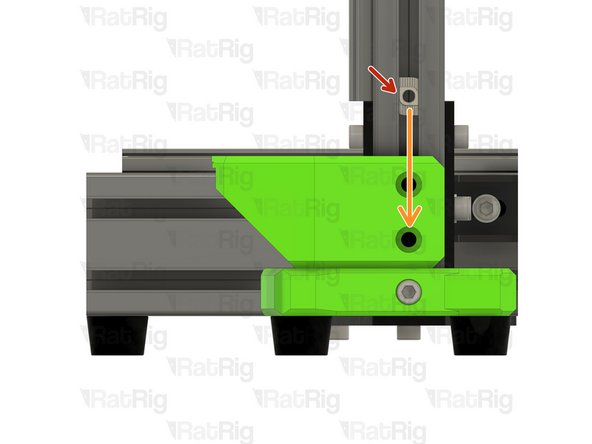
Loosely thread the 3030 T-Nuts onto the M6x12 screws. Do not tighten them at this point.
-
Position the Z-axis motor mount as shown. The base should rest on the rear feet
-
Fasten both M6x12 screws to secure the mount to the frame
-
Take care not to over tighten the M6x12 screws as you can damage the printed part.
-
-
-
3030 Drop In T-Nut M6
-
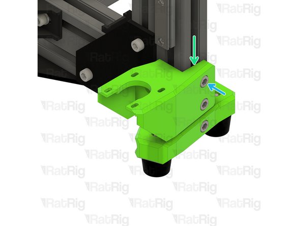
Slide the 3030 T-Nut behind the lower screw hole on the Z-axis motor mount as shown
-
Fasten the M6x12 screw into the 3030 T-Nut
-
Take care not to over tighten the M6x12 screw as you can damage the printed part
-
Slide the 3030 T-Nut behind the upper screw hole on the Z-axis motor mount as shown
-
Fasten the M6x12 screw into the 3030 T-Nut
-
Take care not to over tighten the M6x12 screw as you can damage the printed part
-
-
-
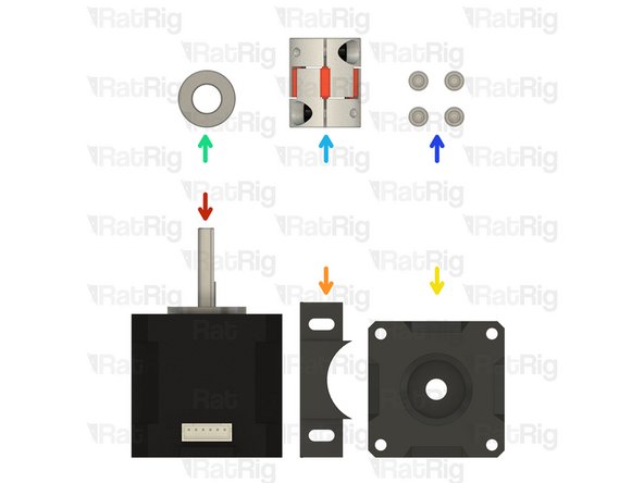
1x 40mm NEMA17 Stepper Motor
-
z_motor_cage_plug printed part
-
pillow_block printed part
-
1x Axial Thrust Bearing
-
1x Spider Coupler
-
4x M3x18 Cap Head Screw
-
-
-
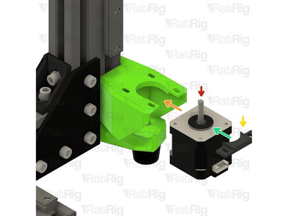
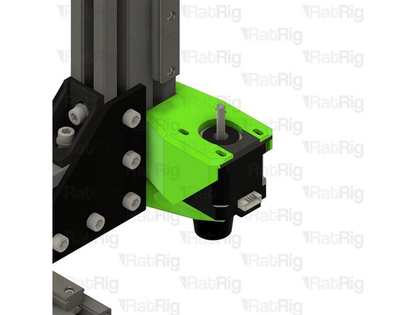
40mm NEMA17 Stepper Motor
-
Slide the stepper motor into the mount as shown
-
z_motor_cage_plug printed part
-
Insert the z_motor_cage_plug to fill the gap after the motor is installed
-
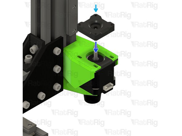
pillow_block printed part
-
Place the pillow_block printed part on top of the motor mount. The stepper motor shaft should pass through the middle
-
-
-
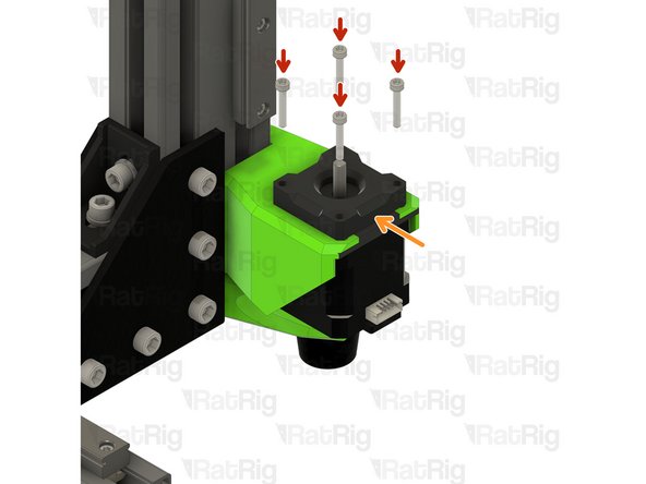
4x M3x18 Cap Head Screw
-
The holes in the Z-axis motor mount are slotted to allow adjustment. This will be performed at a later step. For now, push the motor as far back (towards the frame) as possible and fasten all four M3x18 screws
-
Take care not to over tighten the M3x18 screws as you can damage the printed parts
-
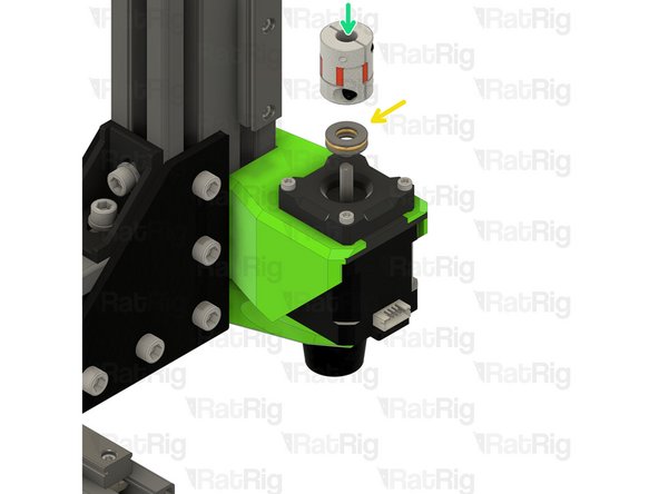
Install the axial thrust bearing over the shaft of the stepper motor. It should sit within the pillow_block printed part
-
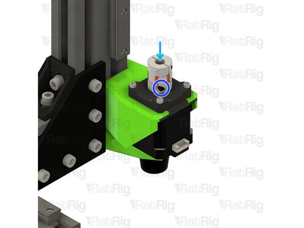
Spider Coupler
-
Apply downwards pressure on the spider coupler to compress the axial thrust bearing
-
Tighten the lower screw on the spider coupler whilst applying downwards force as stated above
-


Cancel: I did not complete this guide.
20 other people completed this guide.