Steps
19
- 04. Z-Axis Assembly 19 steps

In Progress
This guide is currently being written. Reload periodically to see the latest changes.

Private
This guide will not appear in search results and can only be viewed by team members!
Quiz
0
-
-
1x T-Slot extrusion 40120 - 250mm
-
3x M12x25 Countersink screws
-
3x M12 Washer
-
3x M12x25 Cap Head Screw
-
Rat Rig StrongHold ONE CNC - Z-Axis Bottom 10mm
-
Rat Rig StrongHold ONE CNC - Z-Axis Top 10mm
-
-
-
T-Slot extrusion 40120 - 502mm
-
Rat Rig StrongHold ONE CNC - Z-Axis Bottom 10mm
-
3x M12x25 Countersink screws
-
Both plates must be facing upwards.
-
Rat Rig StrongHold ONE CNC - Z-Axis Top 10mm
-
3x M12 Washer
-
3x M12x25 Cap Head Screw
-
-
-
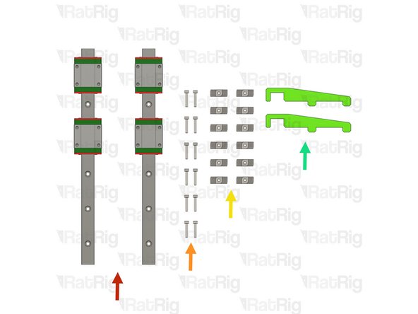
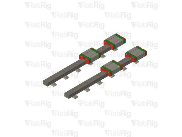
2x Linear Rail - MGN15 250mm + 2 x MGN15C carriage
-
12x M3x16 Cap Head screws
-
12x 4040 Drop-in T-Nut - M3
-
2x align_40120_mgn15 printed part
-
-
-
The linear rails are supplied with a protective oil coating on them. It is strongly recommended to prepare your work surface with paper towels and to wear disposable gloves.
-
Paper Towels
-
Linear Rail
-
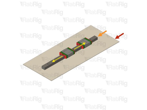
With the rail still on the absorbent paper towels, carefully and slowly move the carriage from one end of the rail to the other
-
Small changes in resistance are normal, but the carriage becoming very hard to push, or binding completely are not
-
If the carriage does not move smoothly, or binds completely, refer to the Linear Rail Troubleshooting Guide
-
The linear rail carriages are not interchangeable. Do not try to use a carriage on a different linear rail than the one it was supplied with.
-
Check this guide if one or more carriages don't move smoothly.
-
-
-
Do not allow the linear rail carriages to leave the end of the rail at any point
-
MGN15 Linear Rail
-
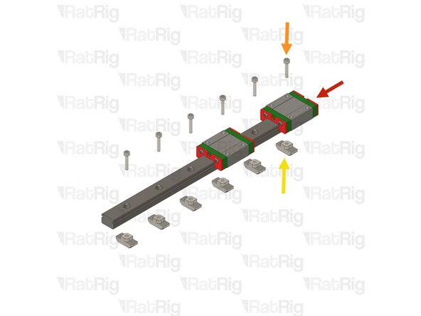
Insert an M3x16 cap head screw in each of the holes on the linear rail
-
Loosely thread a 4040 T-Nut on to each of the M3x16 screws
-
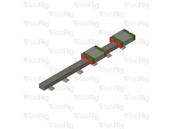
Repeat these instructions for the second linear rail
-
-
-
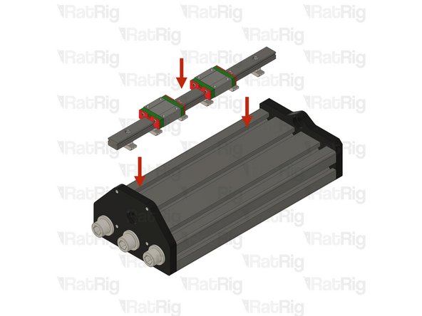
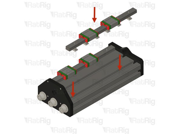
Place one Z linear rail assembly on the designated T-slot.
-
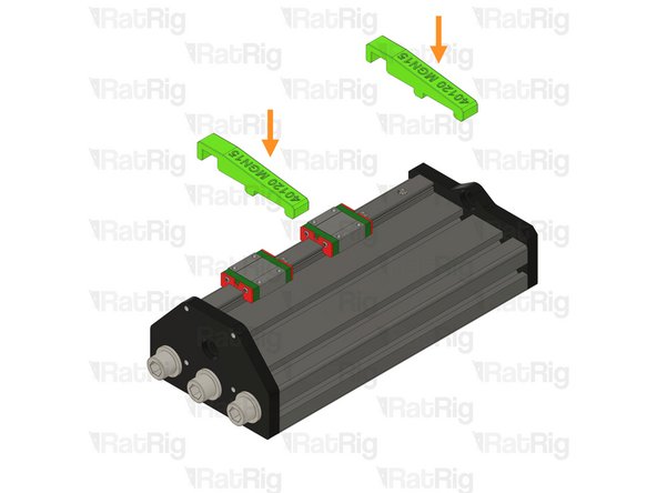
Insert the two align_40120_mgn15 printed jigs in the T-Slot and rail.
-
Make sure the align_40120_mgn15 printed jigs are correctly placed and centering the rail on the T-slot
-
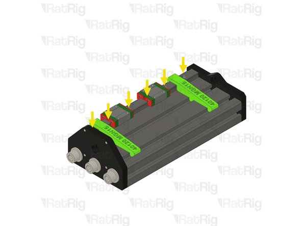
Tighten the linear rails screws one at a time starting from the front and making your way towards the back, one by one.
-
MGN15 Rails should be tightened to 98 N-cm of torque, overtightening the screws will result in rail binding.
-
-
-
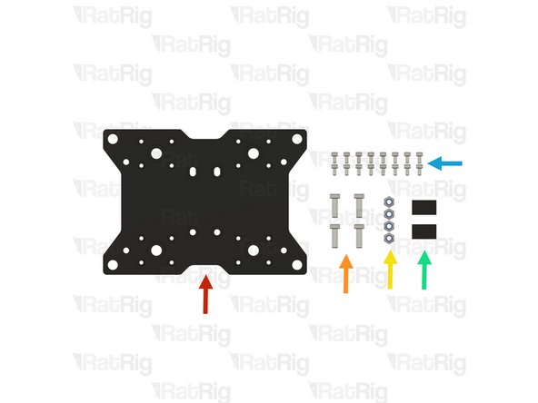
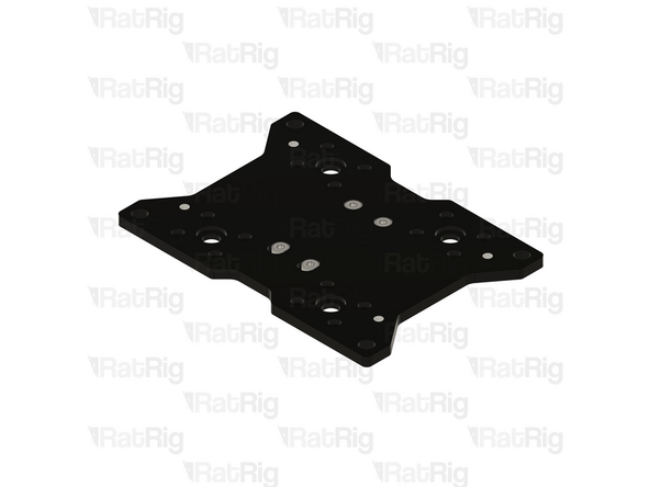
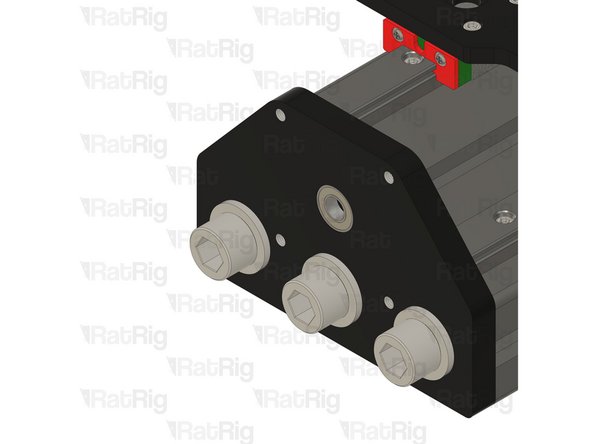
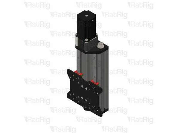
Rat Rig Mill - Z Plate
-
4x M5x16 Low Head Screw
-
4x M5 Nylon Locking Hex Nuts
-
2x Nut Block for TR8x4
-
16x M3x6 Cap Head Screws
-
-
-
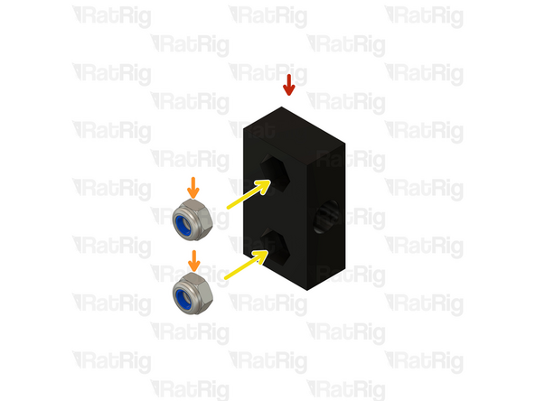
Nut Block for TR8x8
-
M5 Nylon Locking Hex Nut
-
Insert the M5 Locking Hex Nuts in to the Nut Block
-
Prepare two assemblies.
-
-
-
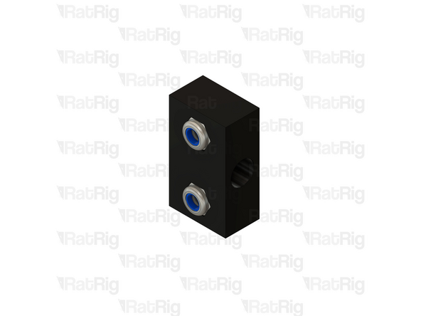
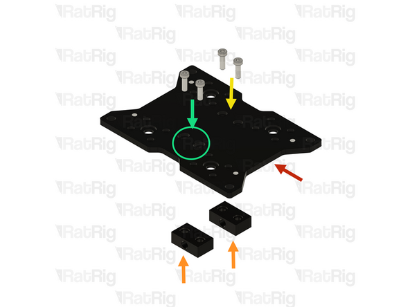
Rat Rig Mill - Z Plate
-
Nut Block for TR8x4 assembly from the last step.
-
The M5 Nylon Locking Hex Nuts, must be facing away from the Y gantry plate.
-
Gently tighten the M5x16 Low Head Screws on the designated holes.
-
Do not overtighten the screws as it will cause binding in the lead screw. Tighten until the nut block is flush with the plate and add half a turn on the screws.
-
Thread the M5x16 Low Head Screws on the designated slot, Do not tighten this Nut Block, it will be adjusted later.
-
-
-
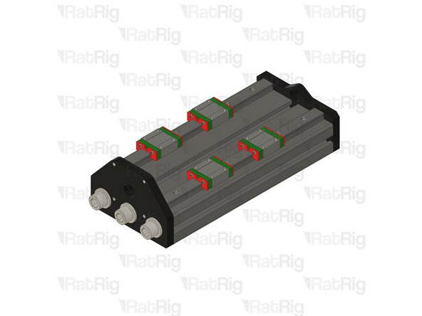
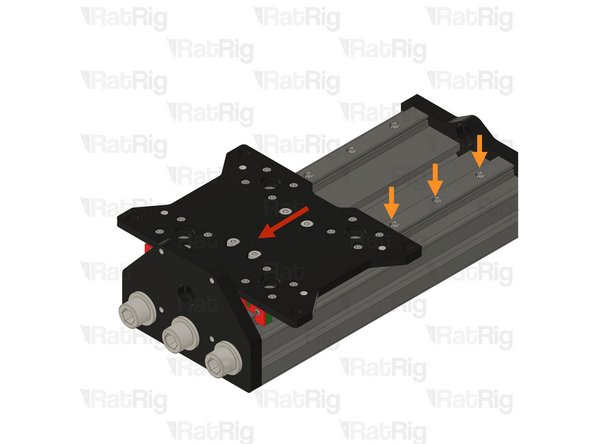
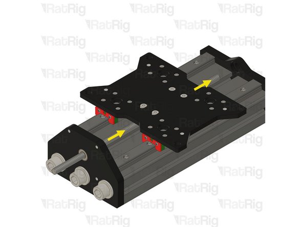
Place the second Z linear rail assembly on the T-slot but DO NOT tighten the screws.
-
Install the Z Joiner assembly on the linear rails.
-
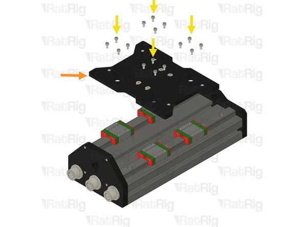
Using the 16x M3x6 Cap Head screws, fasten the XY joiner plate assembly to the mgn15 carriages.
-
MGN15 Rails should be tightened to 98 N-cm of torque, overtightening the screws will result in rail binding.
-
Tip: Blue thread lock can be added to the thread of the M3x6 Cap Head screws.
-
-
-
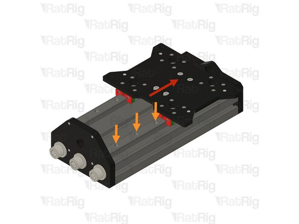
While the second linear rail remains loose, the Z plate should move smoothly without resistance. If you experience any binding or drag, slightly loosen the carriage screws, as they may be overtightened.
-
Be careful to ensure that the Z joiner plate carriages do not detach from the linear rail during the process.
-
Move the Z joiner fully to the front as demonstrated. Then, gradually move it toward the back, exposing one linear rail screw at a time, and tighten each screw as you progress.
-
Ensure that all linear rail screws are tightened from front to back. Avoid overtightening, as this may cause binding and restrict movement.
-
MGN15 Rails should be tightened to 98 N-cm of torque, overtightening the screws will result in rail binding.
-
-
-
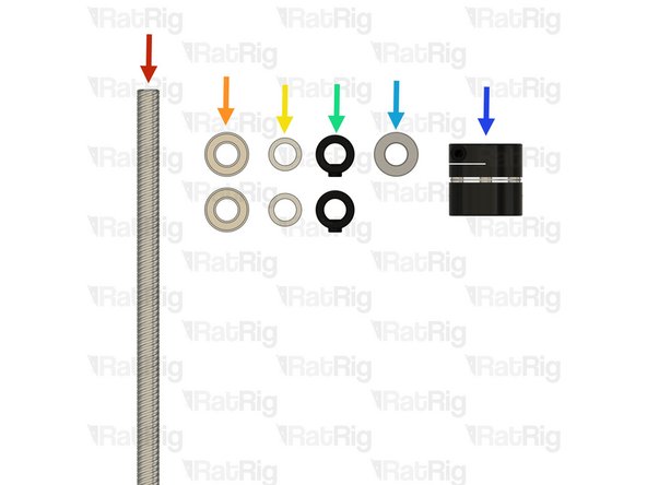
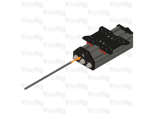
Leadscrew - TR8x4 Metric - 281mm
-
2x Ball Bearing 688ZZ
-
2x Shim - 12 x 8 x 1mm
-
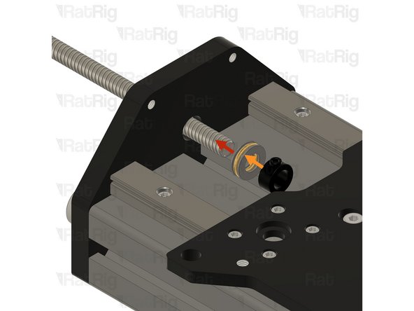
2x Lock Collar
-
Thrust Bearing F8-16M
-
Coupler - Disc Type
-
-
-
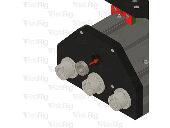
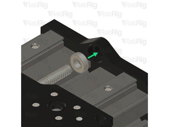
688ZZ Ball bearing
-
Push the ball bearing against the inner side of the plate, ensuring it stays inside the designated groove.
-
Push the Lead Screw through the hole in the ball bearing
-
-
-
Thrust Bearing F8-16M
-
Install the Thrust Bearing on to the exposed end of the Lead Screw as shown
-
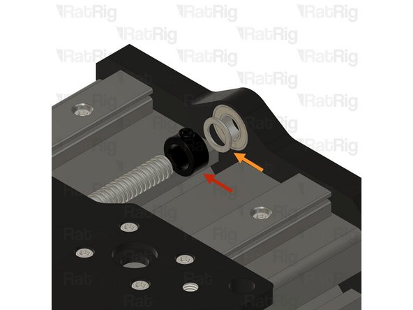
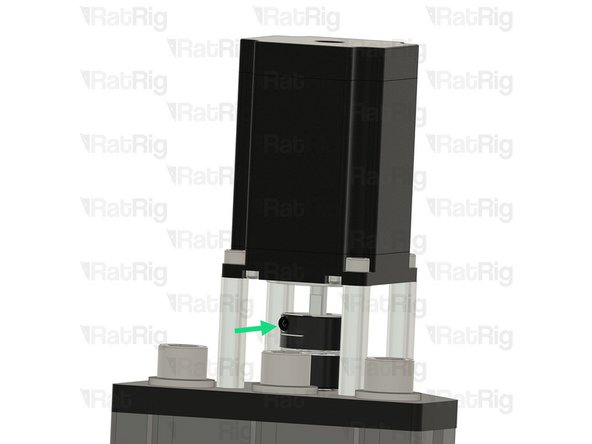
Lock Collar
-
The Precision Shim 12x8x1mm should be in between the 688ZZ Ball bearing and the Lock Collar
-
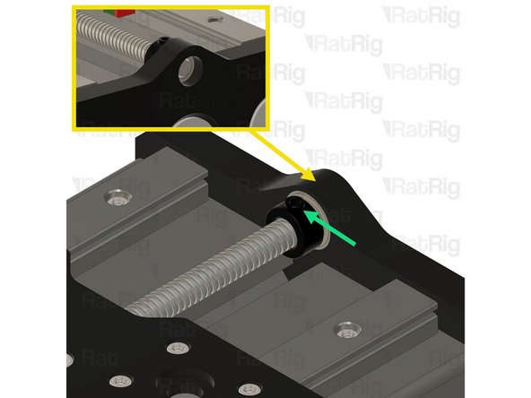
Screw the Lead Screw through both Nut Blocks under the Y joiner plate.
-
-
-
Lock Collar
-
Slide the Lock Collar on to the Lead Screw
-
Precision Shim 12x8x1mm
-
Slide the Precision Shim on to the Lead Screw
-
Ensure the lead screw surface is roughly 1-2mm inside the plate.
-
Tighten the set screw on the lock collar to secure it in place.
-
-
-
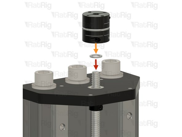
Precision Shim 12x8x1mm
-
Slide the Precision Shim on to the Lead Screw
-
Coupler - Disk Type
-
Install the Coupler on to the exposed end of the Lead Screw.
-
Push the coupler against the metal plate and tighten the set screw.
-
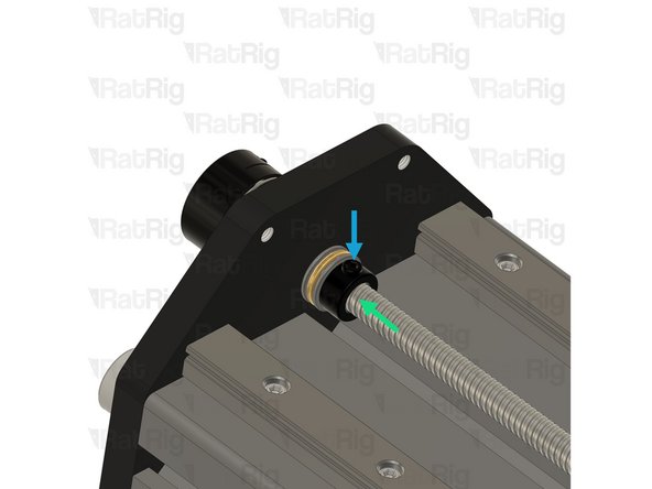
Push the lock collar against the axial bearing to ensure the axial bearing is making full contact with both surfaces.
-
Tighten the set screw on the lock collar.
-
-
-
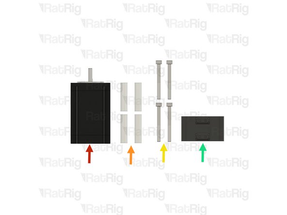
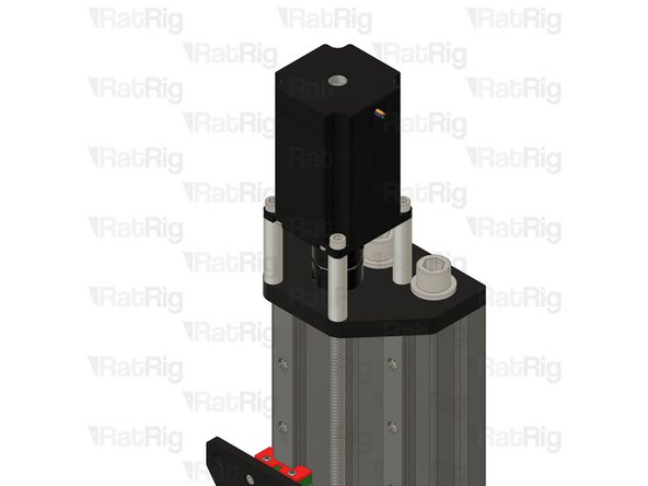
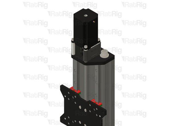
Nema 23 Stepper Motor High Torque
-
4x 40mm Aluminium Spacer
-
4x M5x50 Cap Head Screw
-
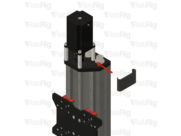
mill_stepper_cable_management printed part
-
-
-
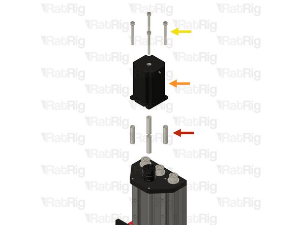
4x 40mm Aluminium Spacer
-
Nema 23 Stepper Motor High Torque
-
4x M5x50 Cap Head Screw
-
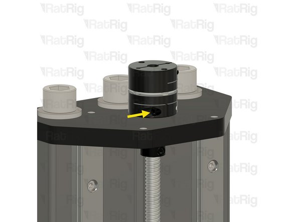
Tighten the set screw on the coupler, to secure the stepper motor shaft to it.
-
-
-
Insert the mill_stepper_cable_management printed part as shown.
-