-
-
1x T-Slot extrusion 40120 - 250mm
-
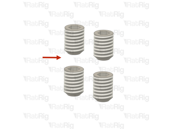
3x M12x25 Countersink screws
-
3x M12 Washer
-
3x M12x25 Cap Head Screw
-
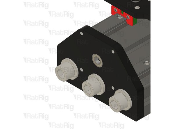
Rat Rig StrongHold ONE CNC - Z-Axis Bottom 10mm
-
Rat Rig StrongHold ONE CNC - Z-Axis Top 10mm
-
-
-
T-Slot extrusion 40120 - 502mm
-
Rat Rig StrongHold ONE CNC - Z-Axis Bottom 10mm
-
3x M12x25 Countersink screws
-
Both plates must be facing upwards.
-
Rat Rig StrongHold ONE CNC - Z-Axis Top 10mm
-
3x M12 Washer
-
3x M12x25 Cap Head Screw
-
-
-
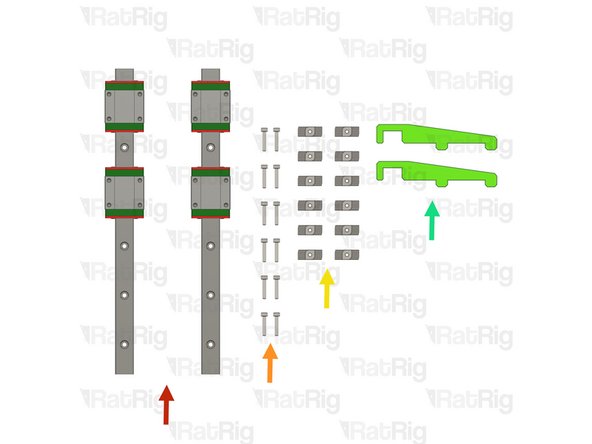
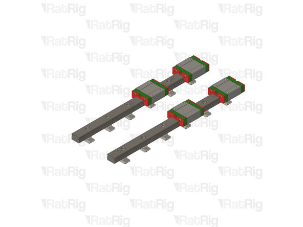
2x Linear Rail - MGN15 250mm + 2 x MGN15C carriage
-
12x M3x16 Cap Head screws
-
12x 4040 Drop-in T-Nut - M3
-
2x align_40120_mgn15 printed part
-
-
-
The linear rails are supplied with a protective oil coating on them. It is strongly recommended to prepare your work surface with paper towels and to wear disposable gloves.
-
Paper Towels
-
Linear Rail
-
With the rail still on the absorbent paper towels, carefully and slowly move the carriage from one end of the rail to the other
-
Small changes in resistance are normal, but the carriage becoming very hard to push, or binding completely are not
-
If the carriage does not move smoothly, or binds completely, refer to the Linear Rail Troubleshooting Guide
-
The linear rail carriages are not interchangeable. Do not try to use a carriage on a different linear rail than the one it was supplied with.
-
Check this guide if one or more carriages don't move smoothly.
-
-
-
Do not allow the linear rail carriages to leave the end of the rail at any point
-
MGN15 Linear Rail
-
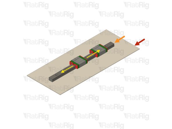
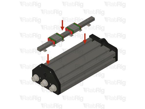
Insert an M3x16 cap head screw in each of the holes on the linear rail
-
Loosely thread a 4040 T-Nut on to each of the M3x16 screws
-
Repeat these instructions for the second linear rail
-
-
-
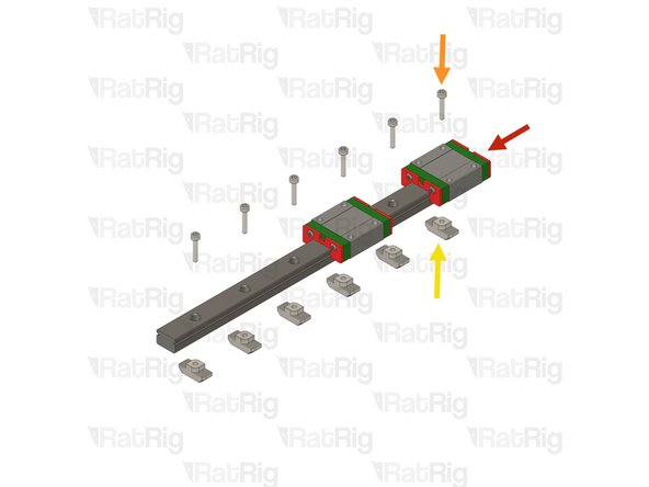
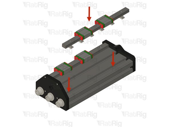
Place one Z linear rail assembly on the designated T-slot.
-
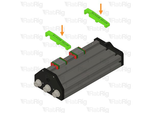
Insert the two align_40120_mgn15 printed jigs in the T-Slot and rail.
-
Make sure the align_40120_mgn15 printed jigs are correctly placed and centering the rail on the T-slot
-
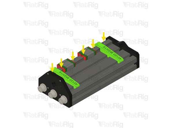
Tighten the linear rails screws one at a time starting from the front and making your way towards the back, one by one.
-
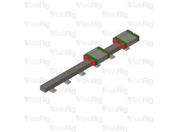
MGN15 Rails should be tightened to 98 N-cm of torque, overtightening the screws will result in rail binding.
-
-
-
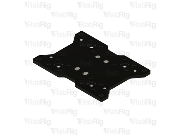
Rat Rig Mill - Z Plate
-
4x M5x16 Low Head Screw
-
4x M5 Nylon Locking Hex Nuts
-
2x Nut Block for TR8x4
-
16x M3x6 Cap Head Screws
-
-
-
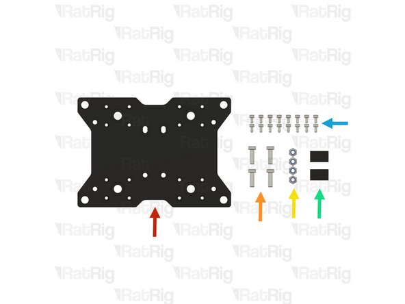
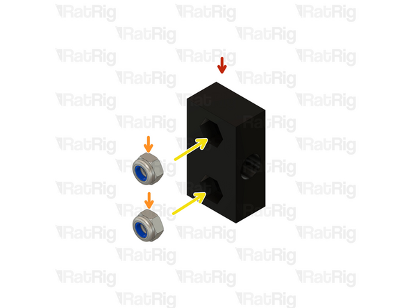
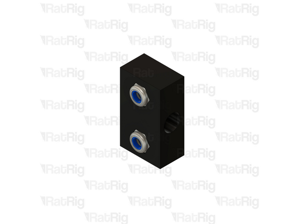
Nut Block for TR8x8
-
M5 Nylon Locking Hex Nut
-
Insert the M5 Locking Hex Nuts in to the Nut Block
-
Prepare two assemblies.
-
-
-
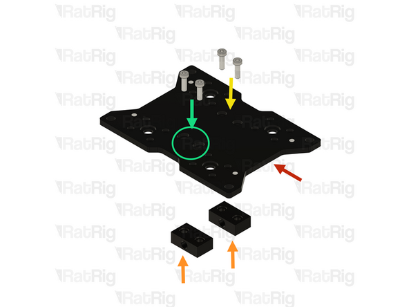
Rat Rig Mill - Z Plate
-
Nut Block for TR8x4 assembly from the last step.
-
The M5 Nylon Locking Hex Nuts, must be facing away from the Y gantry plate.
-
Gently tighten the M5x16 Low Head Screws on the designated holes.
-
Do not overtighten the screws as it will cause binding in the lead screw. Tighten until the nut block is flush with the plate and add half a turn on the screws.
-
Thread the M5x16 Low Head Screws on the designated slot, Do not tighten this Nut Block, it will be adjusted later.
-
-
-
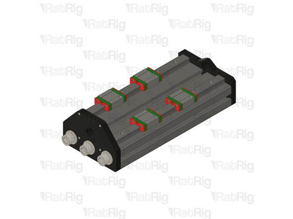
Place the second Z linear rail assembly on the T-slot but DO NOT tighten the screws.
-
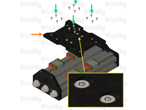
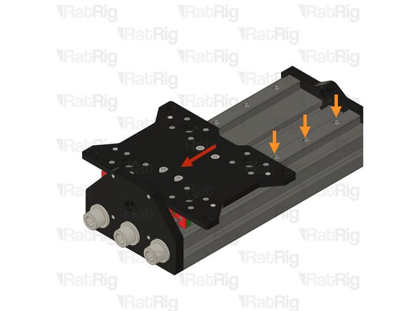
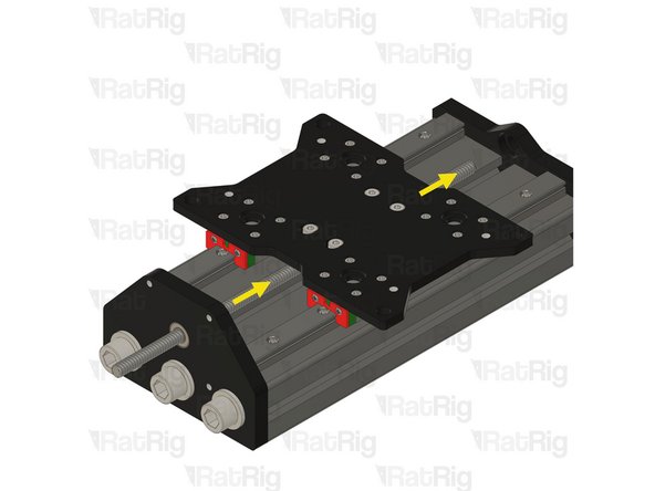
Install the Z Joiner assembly on the linear rails.
-
Ensure the M5 screw slots are facing the Rat Rig StrongHold ONE CNC - Z-Axis Bottom 10mm side as shown.
-
Using the 16x M3x6 Cap Head screws, fasten the XY joiner plate assembly to the mgn15 carriages.
-
MGN15 Rails should be tightened to 98 N-cm of torque, overtightening the screws will result in rail binding.
-
Tip: Blue thread lock can be added to the thread of the M3x6 Cap Head screws.
-
-
-
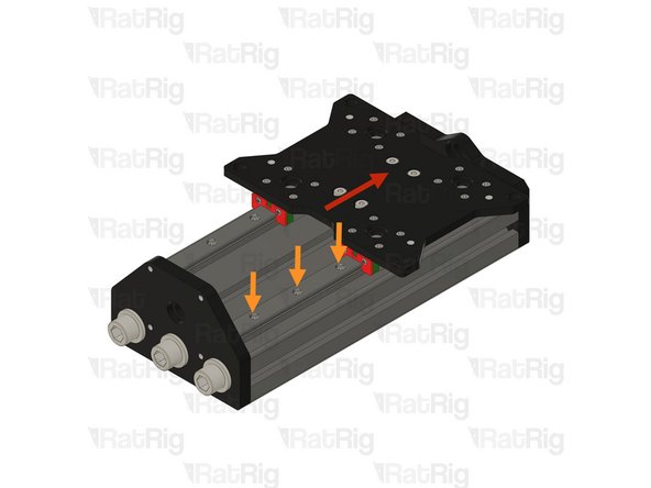
While the second linear rail remains loose, the Z plate should move smoothly without resistance. If you experience any binding or drag, slightly loosen the carriage screws, as they may be overtightened.
-
Be careful to ensure that the Z joiner plate carriages do not detach from the linear rail during the process.
-
Move the Z joiner fully to the front as demonstrated. Then, gradually move it toward the back, exposing one linear rail screw at a time, and tighten each screw as you progress.
-
Ensure that all linear rail screws are tightened from front to back. Avoid overtightening, as this may cause binding and restrict movement.
-
MGN15 Rails should be tightened to 98 N-cm of torque, overtightening the screws will result in rail binding.
-
-
-
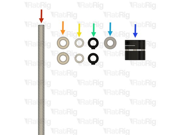
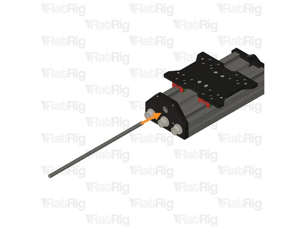
Leadscrew - TR8x4 Metric - 281mm
-
2x Ball Bearing 688ZZ
-
2x Shim - 12 x 8 x 1mm
-
2x Lock Collar
-
Thrust Bearing F8-16M
-
Coupler - Disc Type
-
-
-
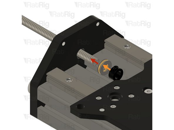
688ZZ Ball bearing
-
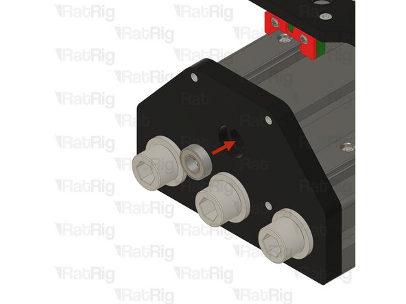
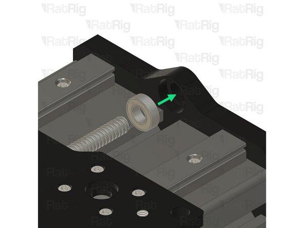
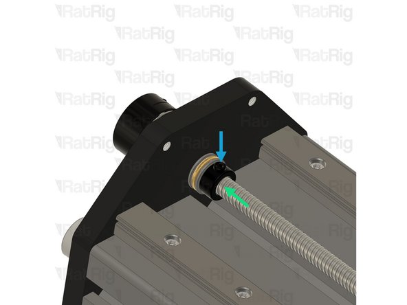
Push the ball bearing against the inner side of the plate, ensuring it stays inside the designated groove.
-
Push the Lead Screw through the hole in the ball bearing
-
-
-
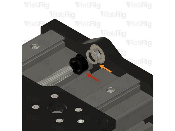
Thrust Bearing F8-16M
-
Install the Thrust Bearing on to the exposed end of the Lead Screw as shown
-
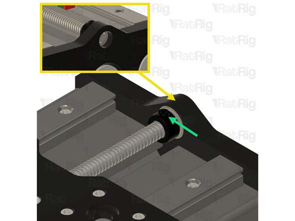
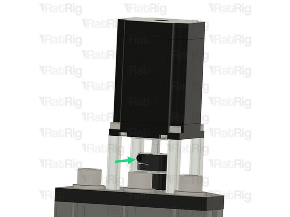
Lock Collar
-
The Precision Shim 12x8x1mm should be in between the 688ZZ Ball bearing and the Lock Collar
-
Screw the Lead Screw through both Nut Blocks under the Y joiner plate.
-
-
-
Precision Shim 12x8x1mm
-
Slide the Precision Shim on to the Lead Screw
-
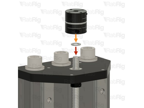
Coupler - Disk Type
-
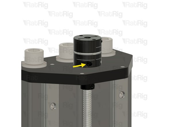
Install the Coupler on to the exposed end of the Lead Screw.
-
Push the coupler against the metal plate and tighten the set screw.
-
Push the lock collar against the axial bearing to ensure the axial bearing is making full contact with both surfaces.
-
Tighten the set screw on the lock collar.
-
-
-
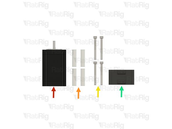
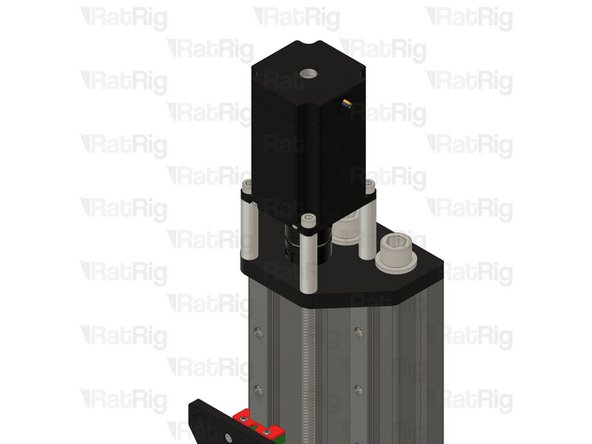
Nema 23 Stepper Motor High Torque
-
4x 40mm Aluminium Spacer
-
4x M5x50 Cap Head Screw
-
mill_stepper_cable_management printed part
-
-
-
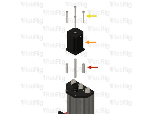
4x 40mm Aluminium Spacer
-
Nema 23 Stepper Motor High Torque
-
4x M5x50 Cap Head Screw
-
Tighten the set screw on the coupler, to secure the stepper motor shaft to it.
-
-
-
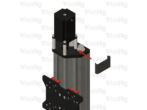
Insert the mill_stepper_cable_management printed part as shown.
-
-
-
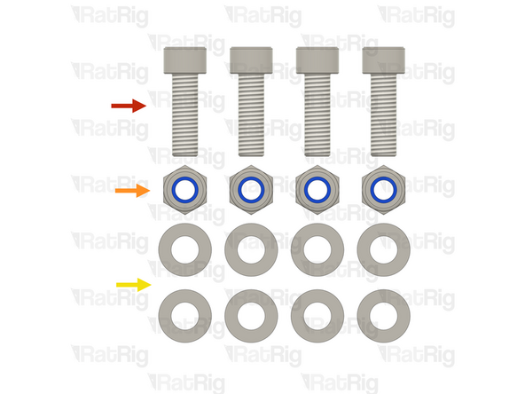
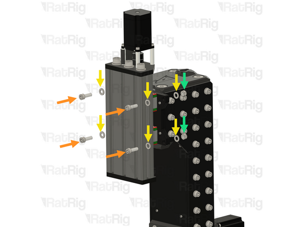
4x M8x25 Cap Head Screw
-
4x M8 Nylon Locking Hex Nut
-
8x M8 Washer
-
-
-
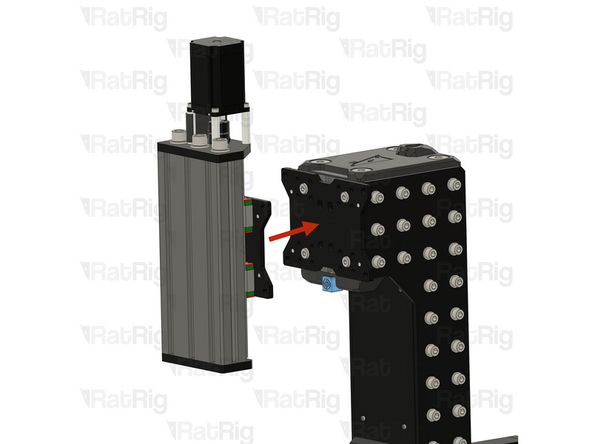
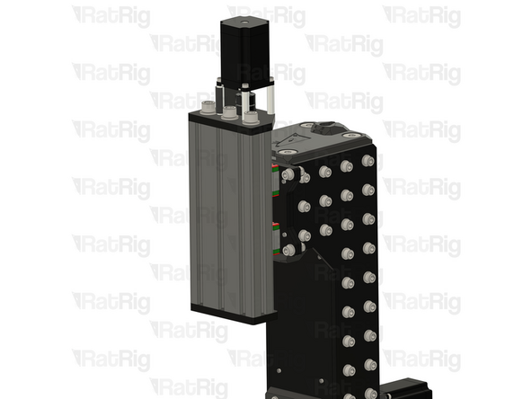
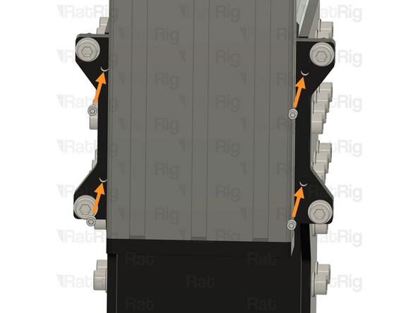
Place the Z-axis assembly on the Z tower, ensuring the M8 Low Head
-
The Z-axis is heavy and difficult to manage alone. Please request assistance from another person to hold the Z-axis while you tighten the screws.
-
Assemble the M8x25 cap head screws by inserting them through the M8 washers and the Z plates. Then, place an M8 washer on the rear and secure everything with an M8 nylon locking nut.
-
4x M8x25 Cap Head Screw
-
8x M8 Washer
-
4x M8 Nylon Locking Hex Nut
-
-
-
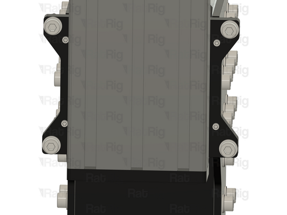
4x M6x8 Set screws
-
Look through the threaded holes; there should be no light visible on the other side. If you see light, it indicates that one of the Z plates is installed upside down. Visit this 02. Z Tower Assembly and flip the Z plate upside down.
-
Lightly thread the set screws into the designated holes. Once they reach the rear Z plate, stop tightening.
-
These screws are intended to assist the user in tramming the spindle during the commissioning process.
-
-
-
Select your work tool to continue with the next guide:
-
2.2KW Spindle - 05. Spindle
-
Rat Rig Router - 06. Rat Rig Router
-