
-
-
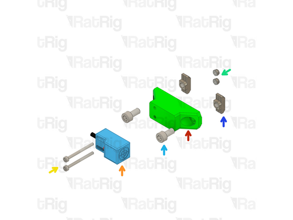
3x SN04-N2 Proximity Sensor
-
2x sh_one_xz_endstop_mount Printed Part
-
sh_one_y_endstop_mount Printed Part
-
2x M3x20 Cap Head Screw
-
4x M3x35 Cap Head Screw
-
6x M3 Nylon Locking Hex Nut
-
6x M6x12 Cap Head Screw
-
6x 4040 Drop-in T-Nut - M6
-
-
-
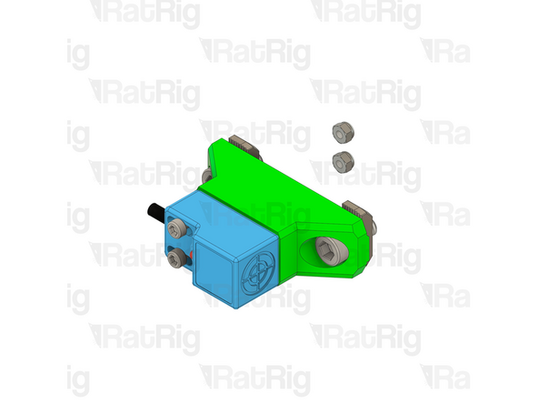
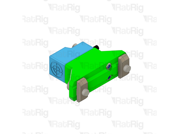
sh_one_xz_endstop_mount Printed Part
-
Proximity Sensor
-
Insert the M3x20 Cap Head Screws on the endstop and through the XZ mount
-
Tighten the M3x20 Cap Head Screws with the M3 Nylon Locking Hex Nut
-
Insert a two M6x12 Cap Head Screws on the mount
-
Lightly thread the M6 T-nuts on the screws, Don't tighten them
-
Take care not to over tighten the screws as you can damage the printed parts
-
-
-
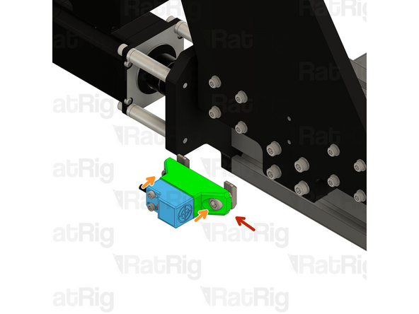
sh_one_y_endstop_mount Printed Part
-
Proximity Sensor
-
Insert the M3x35 Cap Head Screws on the endstop and through the Y mount
-
Tighten the M3x35 Cap Head Screws with the M3 Nylon Locking Hex Nut
-
Insert a two M6x12 Cap Head Screws on the mount
-
Lightly thread the M6 T-nuts on the screws, Don't tighten them
-
Take care not to over tighten the screws as you can damage the printed parts
-
-
-
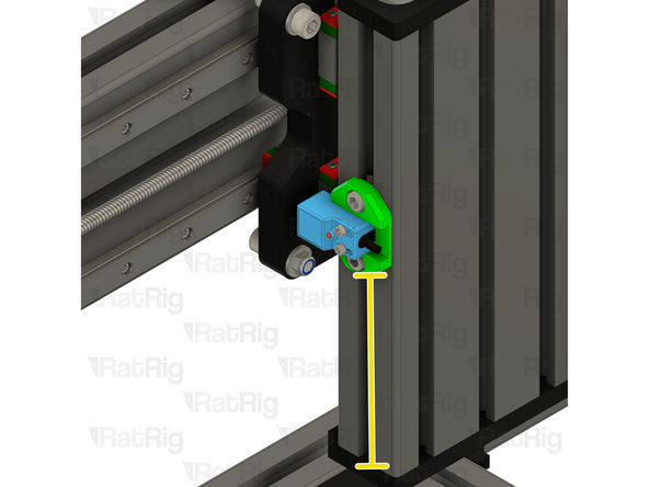
Z Endstop assembly from Step 2
-
Lighty tighten the M6x12 Cap Head Screws to secure the endstop assembly to the Z-Axis
-
The marked distance should measure roughly 111mm
-
Tighten the M6x12 screws
-
Take care not to over tighten the screws as you can damage the printed parts
-
-
-
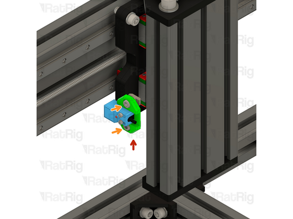
XZ Endstop assembly from Step 2
-
Lighty tighten the M6x12 Cap Head Screws to secure the endstop assembly to the X-Axis
-
The marked distance should measure roughly 34mm
-
Tighten the M6x12 screws
-
Take care not to over tighten the screws as you can damage the printed parts
-
-
-
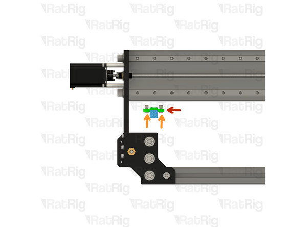
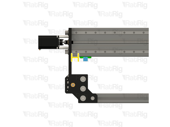
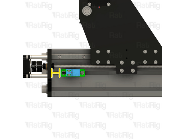
Y Endstop assembly from Step 3
-
Lighty tighten the M6x12 Cap Head Screws to secure the endstop assembly to the Y-Axis
-
The marked distance should measure roughly 22mm
-
Tighten the M6x12 screws
-
Take care not to over tighten the screws as you can damage the printed parts
-
-
-
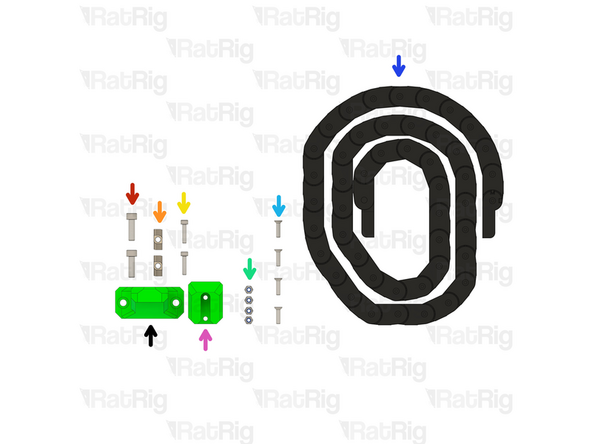
2x M6x20 Cap Head Screw
-
2x 4040 Drop-in T-Nut - M6
-
2x M4x18 Cap Head Screw
-
4x M4 Nylon Locking Hex Nut
-
4x M4 Counter Sink Screw
-
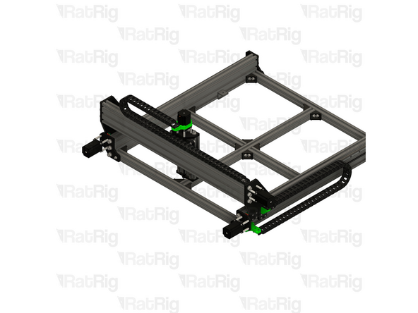
1530mm Drag Chain [ 2100mm for the SH ONE 1250x1250. ]
-
sh_one_gantry_y_dragchain_mount Printed Part
-
sh_one_gantry_y_dragchain_mount Printed Part
-
-
-
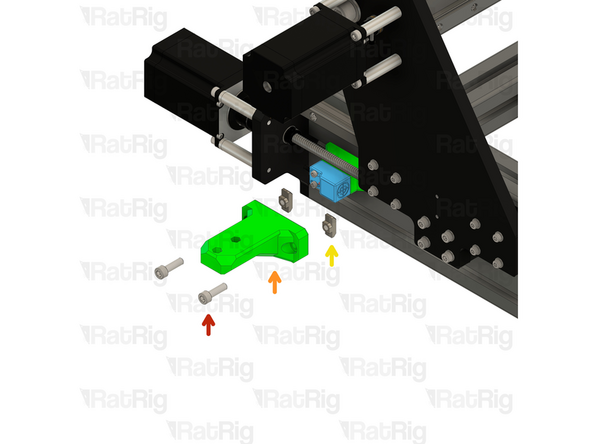
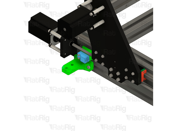
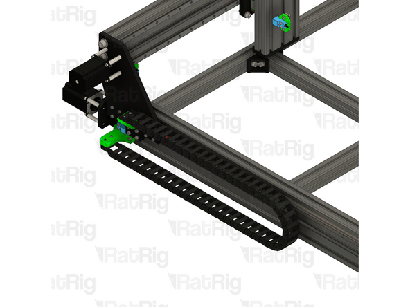
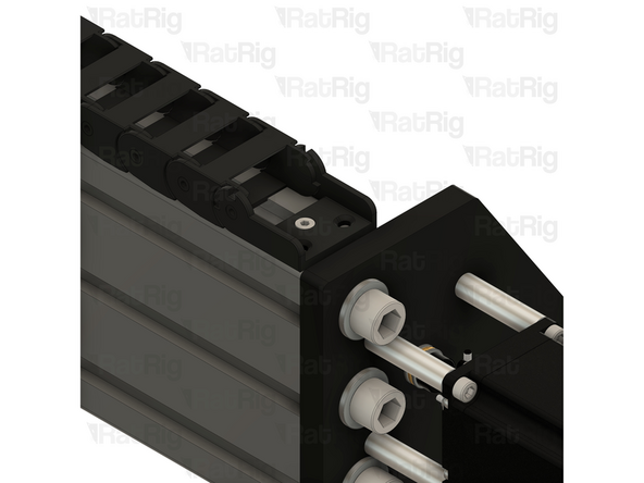
M6x20 Cap Head Screws
-
sh_one_frame_y_dragchain_arm Printed Part
-
4040 Drop-in T-Nut - M6
-
Loosely thread the 4040 T-Nut on to the M6x16 screw. Place it under the Y-Axis Endstop and tighten the screws.
-
Take care not to over tighten the screws as you can damage the printed parts
-
-
-
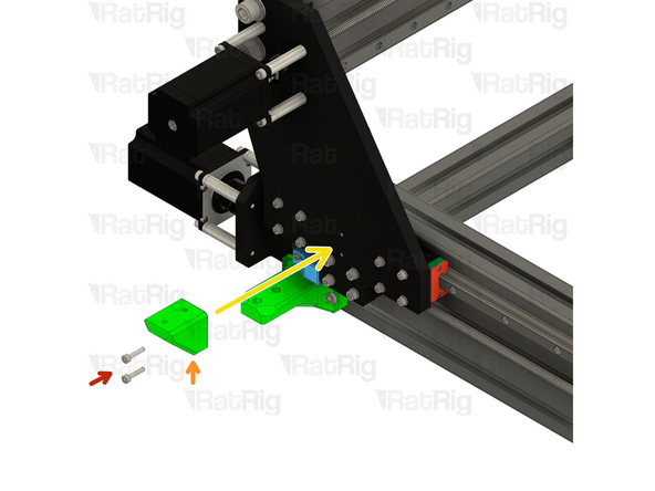
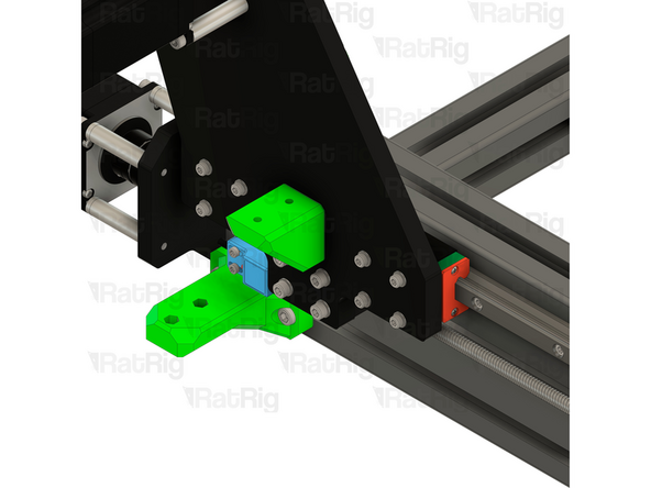
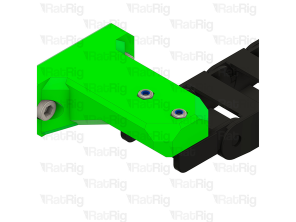
M4x18 Cap Head Screw
-
sh_one_gantry_y_dragchain_mount Printed Part
-
Insert an M4x18 screw through each hole in the front of the printed part and into the existing holes on the XZ plate
-
Take care not to over tighten the screws as you can damage the printed parts
-
-
-
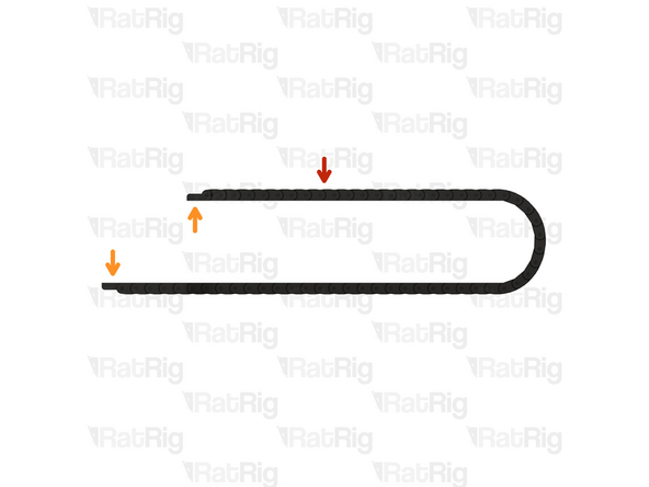
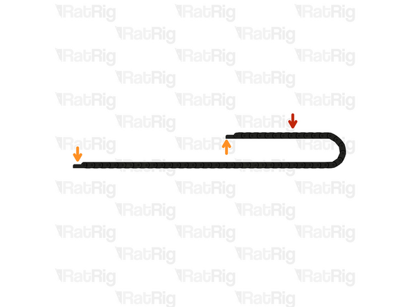
1530mm 15x30 Drag Chain
-
2100mm for the StrongHold ONE.
-
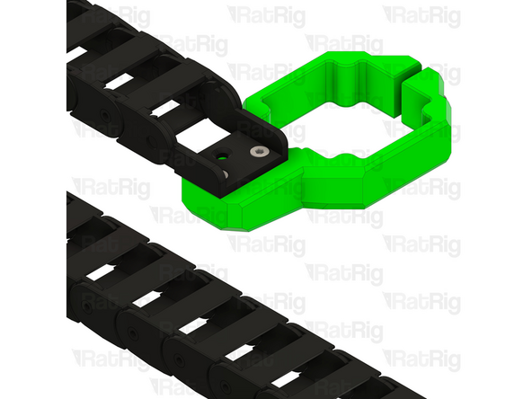
The ends of the drag chain need to be oriented correctly
-
If your drag ends are oriented as shown in the first image, skip to the next step
-
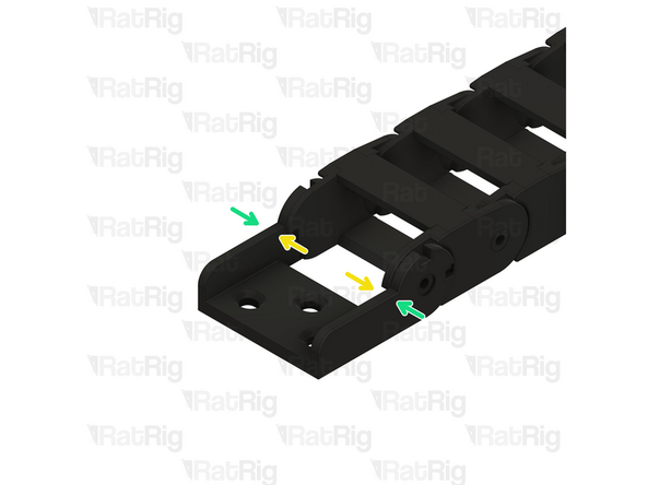
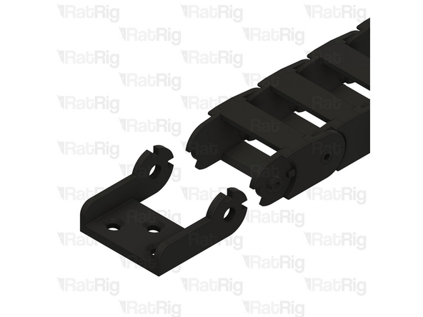
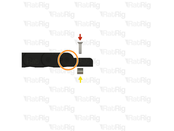
Remove the drag chain end by either compressing or expanding the link in the chain, as shown
-
Once removed, flip the orientation of the end and re-install it.
-
It may be easier to remove the drag chain end by opening the drag chain link next to the end. The drag chain is designed to be opened to allow easier installation and maintenance.
-
-
-
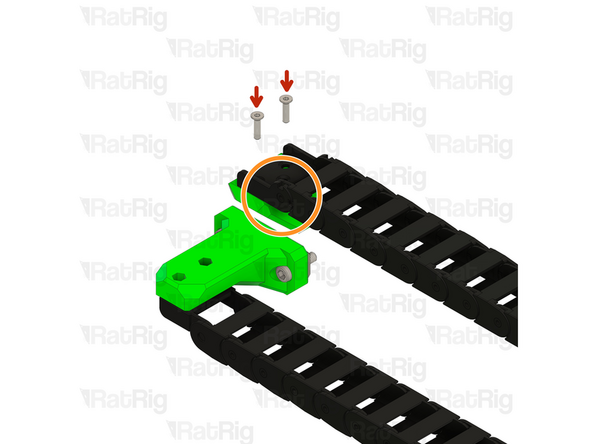
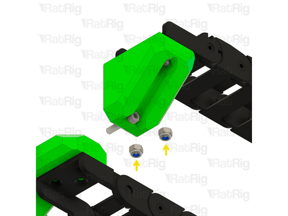
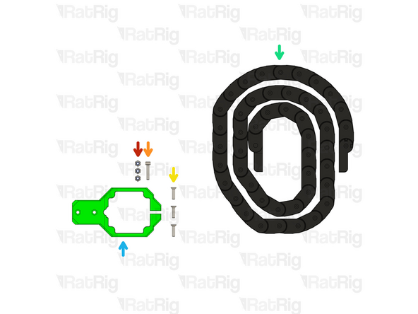
M4x16 Countersunk Screw
-
Drag chain assembly - Female End
-
M4 Nylon Locking Hex Nut
-
Insert an M4x16 screw into each hole in the drag chain and tighten them to the M4 Locking Nuts, securing the drag chain to the mount
-
Take care not to over tighten the screws as you can damage the printed parts
-
-
-
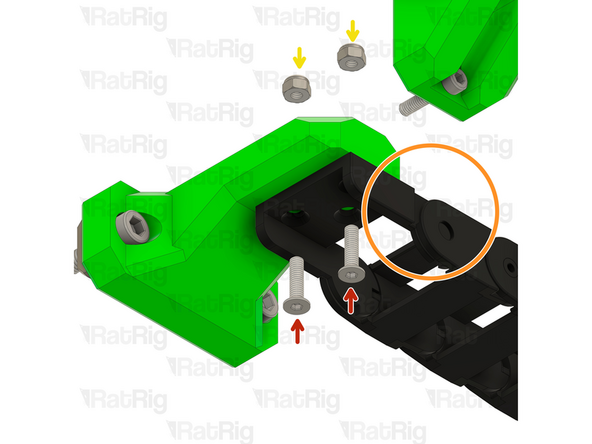
M4x16 Countersunk Screw
-
Drag chain assembly - Male End
-
M4 Nylon Locking Hex Nut
-
Insert an M4x16 screw into each hole in the drag chain and tighten them to the M4 Locking Nuts, securing the drag chain to the mount
-
Take care not to over tighten the screws as you can damage the printed parts
-
-
-
3x M4 Nylon Locking Hex Nut
-
M4x20 Cap Head Screw
-
3x M4x16 Counter Sink Screw
-
1530mm Drag Chain
-
2100mm for the SH ONE 750x1250 or 1250x1250.
-
sh_one_motor_x_dragchain_mount Printed Part
-
-
-
1530mm 30x15 Drag Chain
-
The ends of the drag chain need to be oriented correctly
-
If your drag ends are oriented as shown in the first image, skip to the next step
-
Remove the drag chain end by either compressing or expanding the link in the chain, as shown
-
Once removed, flip the orientation of the end and re-install it.
-
It may be easier to remove the drag chain end by opening the drag chain link next to the end. The drag chain is designed to be opened to allow easier installation and maintenance.
-
-
-
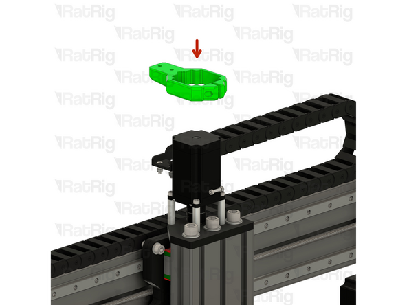
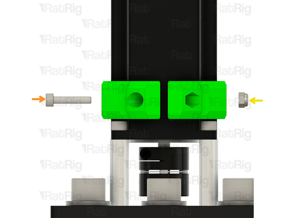
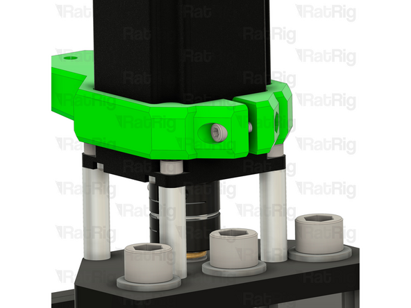
sh_one_motor_x_dragchain_mount Printed Part
-
Slide the sh_one_motor_x_dragchain_mount on to the Z - Axis Stepper Motor
-
M4x20 Cap Head Screw
-
M4 Nylon Locking Hex Nut
-
Take care not to over tighten the screws as you can damage the printed parts
-
-
-
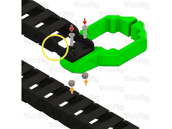
M4x16 Countersunk Screw
-
M4 Nylon Locking Hex Nut
-
Drag chain assembly - Male End
-
Insert an M4x16 screw into each hole in the drag chain and tighten them to the M4 Locking Nuts, securing the drag chain to the mount
-
Take care not to over tighten the screws as you can damage the printed parts
-
-
-
M4x16 Countersunk Screw
-
Drag chain assembly - Female End
-
4040 Drop-in T-Nut - M4
-
Insert the Drag chain end assembly in to the 40120 extrusion slot and tighten the M4x16 Countersunk Screw.
-


Cancel: I did not complete this guide.
One other person completed this guide.
