
-
-
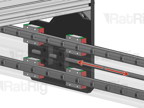
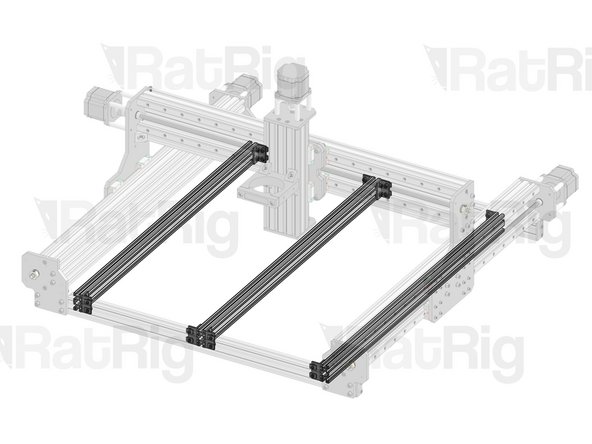
The KillerBee uses 1 motor to drive the X axis and 2 motors to drive the Y axis.
-
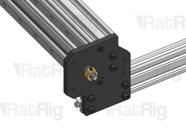
The assembly of each of the 3 drivetrains is the exact same, using the same parts. Only one of the assemblies will be illustrated in this guide, but you should repeat the same steps for all 3.
-
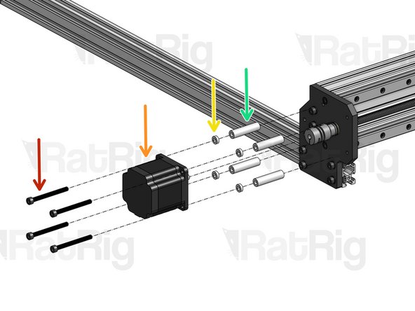
Look at the picture and take note of where the motors should be located in the machine, so you don't assemble them in the wrong side by mistake.
-
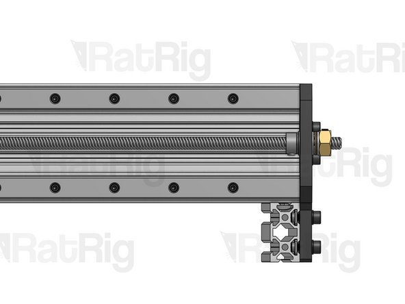
Lay each motor next to the plate where it will be mounted and each lead screw next to its axis, so you don't get anything mixed up. Lead Screws are slightly bigger than the axis where they are mounted.
-
-
-
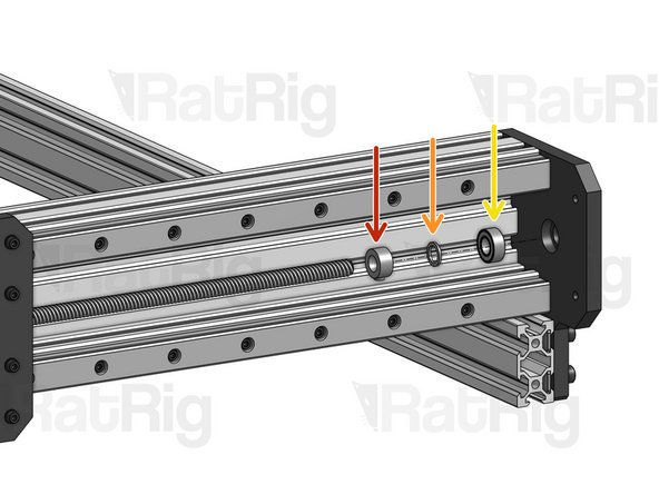
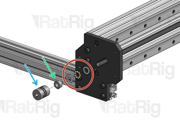
Lead Screw
-
688ZZ Ball Bearing
-
Precision Shim 12x8x1mm
-
Lock Collar 8mm
-
Push the 3 parts agains the inner side of the plate, but don't tighten anything for now.
-
-
-
After screwing the Lead Screw through both Nut Blocks, pull and push it gently, to see if there's any slack.
-
If there is slack, slightly loosen these screws to move one of the Nut block away/towards the other one, until all slack is removed. Refer back to this step for more detailed instructions.
-
-
-
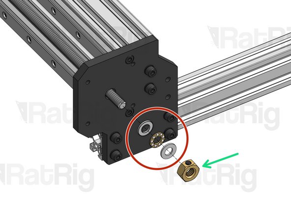
Thrust Bearing
-
Tensioner Nut. For now, screw it in just a tiny bit, so it holds its position.
-
-
-
Thrust Bearing
-
Lock Collar 8mm
-
Flexible Coupling - 1/4" x 8mm. Set in position, don't tighten just yet.
-
-
-
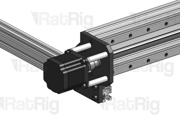
Start by adjusting the position of the Flexible Coupling to make sure that both the Lead Screw and the Nema 23 motor shaft are fully inserted inside the ends of the coupling.
-
Make sure the flat face of the D shaped motor shaft is facing the set screw on the Flexible Coupling. Tighten down the set screws on both sides.
-
Tighten down the larger clamping screws on your coupling.
-
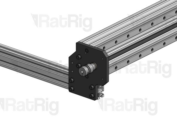
Press the lock collar against the plate and firmly tighten down its set screw.
-
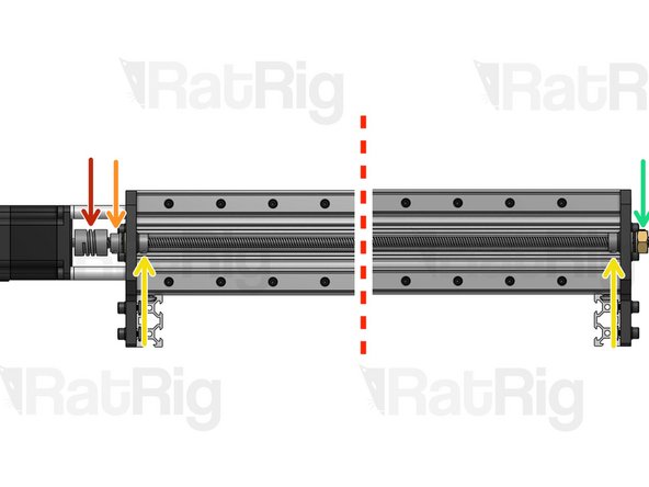
Grab your XY/XZ Carriage firmly, so it doesn't move, and use a spanner to tighten the Tensioner nut until your lead screw is under tension. Excessive tension should be avoided, as it will increase part wear. You may need to adjust tension once you start using the machine, if you notice whip/vibration on the lead screw.
-
Instead of grabbing the carriage, you can also manually spin the lead screw until the carriage has reached its right-most position. In this position the carriage can't move once you start tightening the Tensioner Nut.
-
Press these 2 lock collars against their respective Plates and tighten down their set screws.
-


Cancel: I did not complete this guide.
4 other people completed this guide.
