
Steps
45
- 10. EVA 3.0 Hex Nut Assembly 45 steps

User-Contributed Guide
This guide is not managed by the site's staff.
Quiz
0
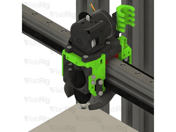
Introduction
This guide covers the assembly of the EVA 3.0 print head. Whilst EVA 3.0 supports multiple combinations of extruder, hot end, and cooling, this guide focuses on the components supplied in the default V-Core 3.1 kit:
- Bondtech LGX Lite extruder
- Phaetus Rapido HF hot end
- 4028 part cooling fan
- Rat Rig “SuperPinda” Probe by P&F
Information regarding other component combinations can be found on the EVA website
-
-
1x Bondtech LGX Lite Extruder
-
1x EVA3 back_core_xy Printed Part
-
1x EVA3 drive_lgx_lite Printed Part
-
1x EVA3 front_universal Printed Part
-
4x Flat Square Nut - M3 (supplied with the LGX Lite - they could be pre-installed inside the extruder)
-
1x EVA3 top_endstop_mgn12c Printed Part
-
18x Hex Nut - M3
-
4x M3x8 Cap Head Screw
-
-
-
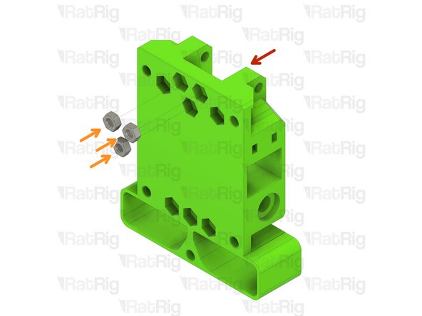
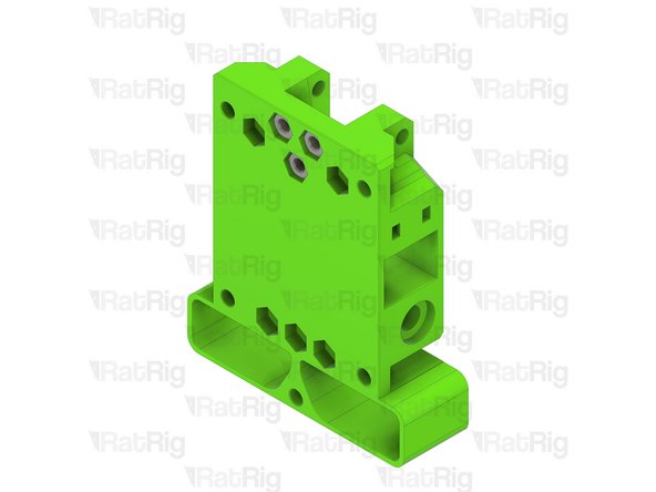
EVA3 top_endstop_mgn12c Printed Part
-
Hex Nut - M3
-
Install an M3 hex nut into each of the three positions shown
-
Set this assembly aside until Step 14
-
-
-
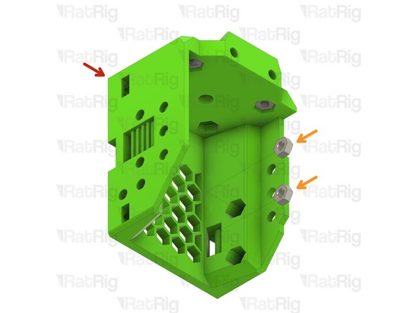
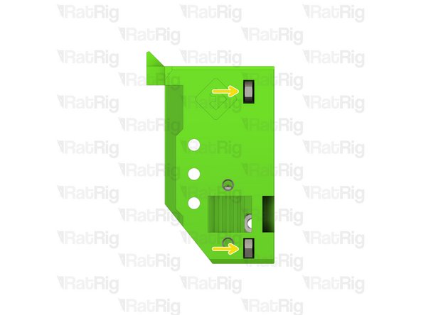
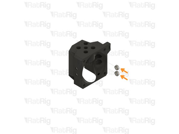
EVA3 universal_front Printed Part
-
Hex Nut - M3
-
Install an M3 hex nut into each position shown, there should be four on the left and two in the top
-
-
-
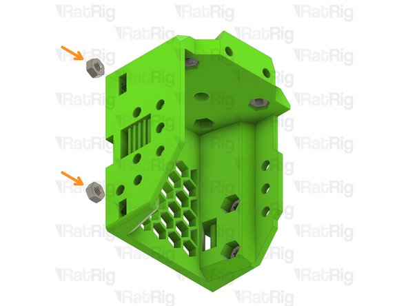
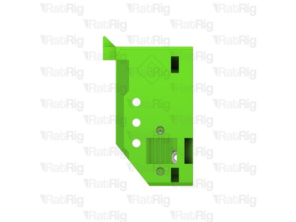
EVA3 universal_front Printed Part
-
Hex Nut - M3
-
Install an M3 hex nut into each position as shown
-
The M3 hex nuts inserted into the side slots must be pulled into position using an M3 cap head screw
-
-
-
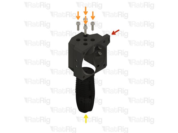
EVA3 universal_front Printed Part
-
Hex Nut - M3
-
Install an M3 hex nut into each position as shown
-
The M3 hex nuts inserted into the side slots must be pulled into position using an M3 cap head screw
-
Set this assembly aside until Step 16
-
-
-
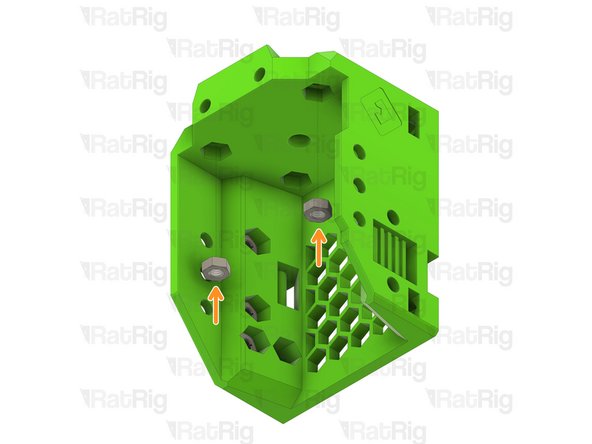
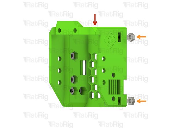
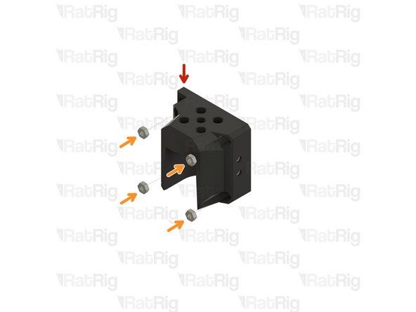
EVA3 back_core_xy Printed Part
-
Hex Nut - M3
-
Install an M3 hex nut into each of the three positions shown
-
Set this assembly aside until Step 19
-
-
-
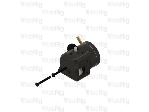
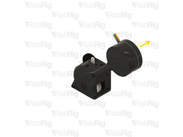
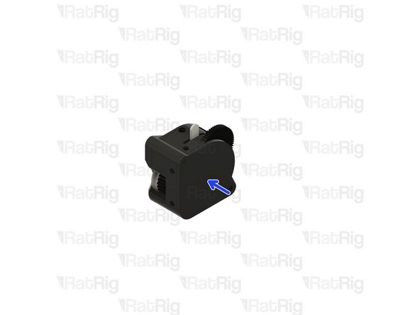
Bondtech LGX Lite extruder
-
Remove the two M3x25 screws holding the Bondtech LGX Lite together
-
Carefully remove the motor from the LGX Lite assembly
-
Set the LGX Lite motor aside until Step 26
-
-
-
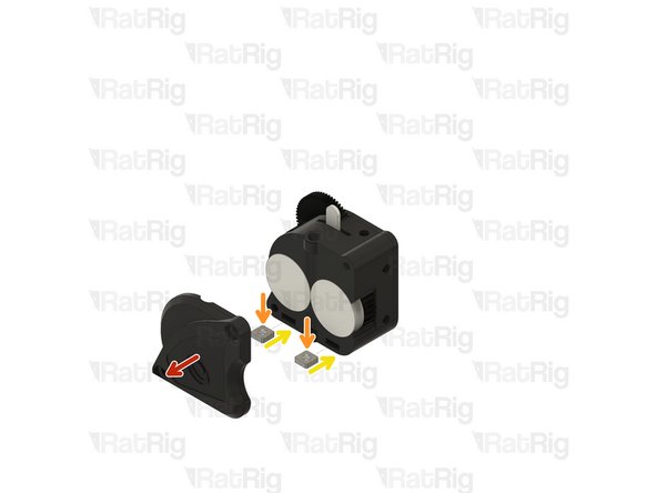
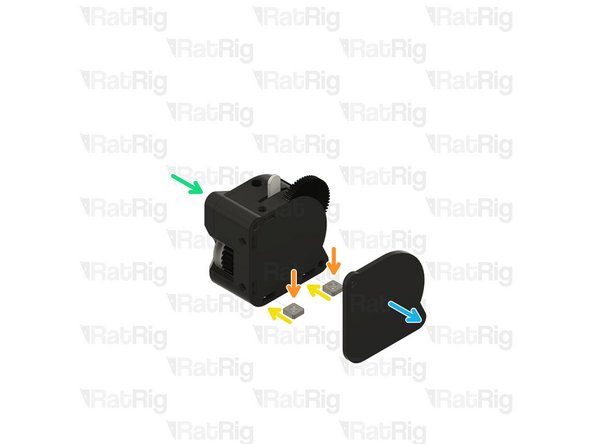
If the 4x Flat Square Nut - M3 are pre-installed inside the LGX Lite, you can skip this step
-
Carefully remove the face plate from the LGX Lite assembly
-
M3 Square Nut
-
Insert one M3 square nut into each of the marked holes on the LGX Lite
-
Re-install the LGX Lite face plate
-
Carefully remove the rear plate from the LGX Lite assembly
-
Insert one M3 square nut into each of the marked holes on the LGX Lite
-
Re-install the LGX Lite back plate
-
-
-
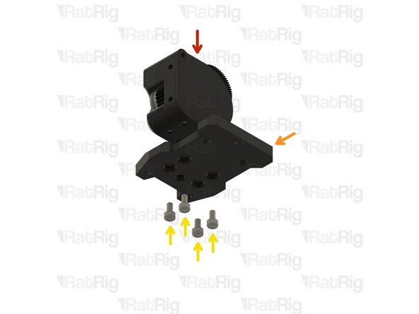
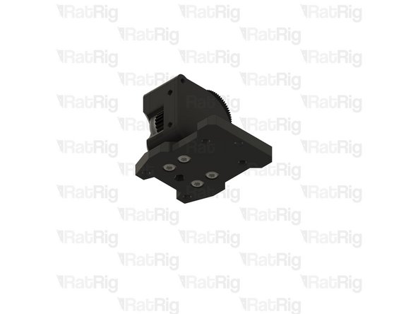
Bondtech LGX Lite assembly
-
EVA3 drive_lgx_lite Printed Part
-
M3x8 Cap Head Screw
-
Install an M3x8 screw into each of the four positions shown. This will secure the LGX Lite extruder to the printed part
-
Take care not to over tighten the M3 screws as you can damage the printed part or the LGX Lite
-
Re-install the two M3x25 screws into the LGX Lite extruder
-
-
-
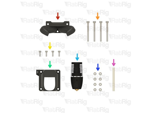
1x EVA3 bottom_horns Printed Part
-
4x M3x35 Cap Head Screw
-
4x M2.5x8 Cap Head Screw (Included with the Phaetus Rapido HF)
-
1x EVA3 hotend_rapido Printed Part
-
1x Phaetus Rapido HF Hotend (The Phaetus Rapido 2 is exactly the same)
-
Follow the included assembly instructions to prepare the Rapido HF for use. The groovemount adapter which is pre-installed must be removed for use on EVA3
-
8x Hex Nut - M3
-
1x 43.7mm PTFE Tube
-
-
-
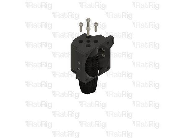
EVA3 hotend_rapido Printed Part
-
Hex Nut - M3
-
Install an M3 hex nut into the four positions as shown
-
-
-
If you are using heat inserts skip to Step 16
-
EVA3 hotend_rapido Printed Part
-
Hex Nut - M3
-
Install an M3 hex nut into each position as shown
-
-
-
Assembly from the previous step
-
M2.5x8 Cap Head Screw
-
Phaetus Rapido HF assembly
-
Insert the four M2.5x8 screws through the printed part and fasten them into the Rapido HF hotend
-
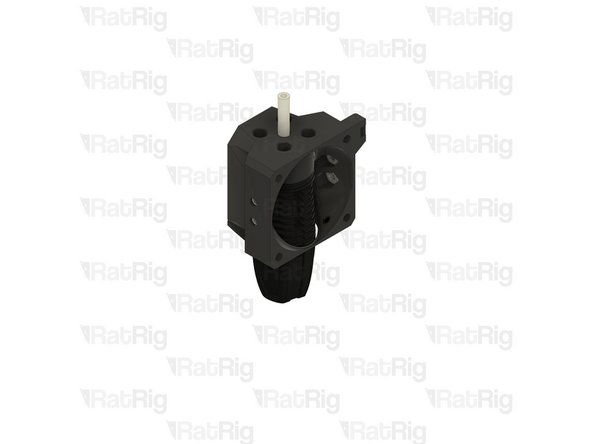
43.7mm PTFE Tube
-
Insert the PTFE tube as shown, ensure it is fully pushed down into the hotend
-
Set this assembly aside until Step 30
-
-
-
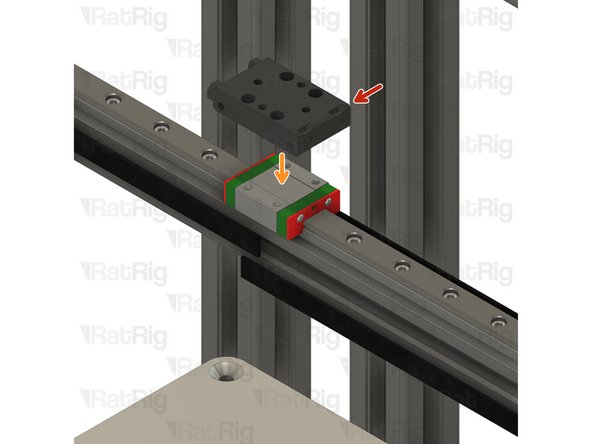
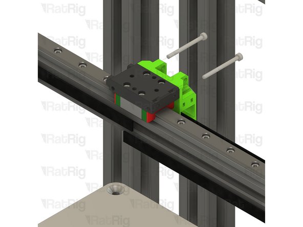
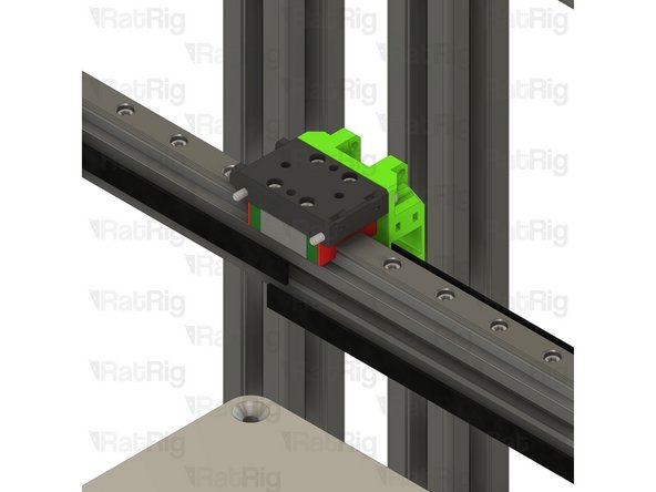
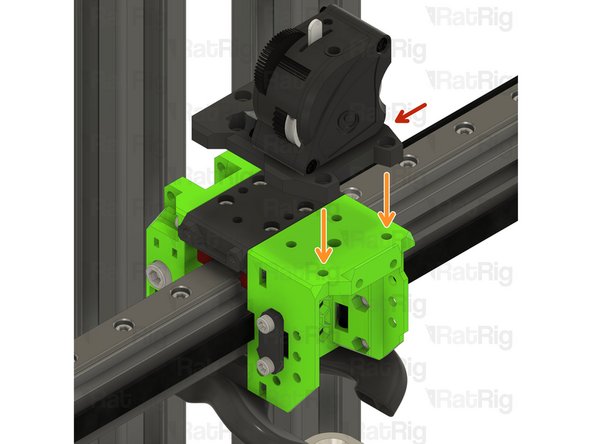
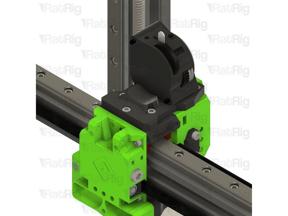
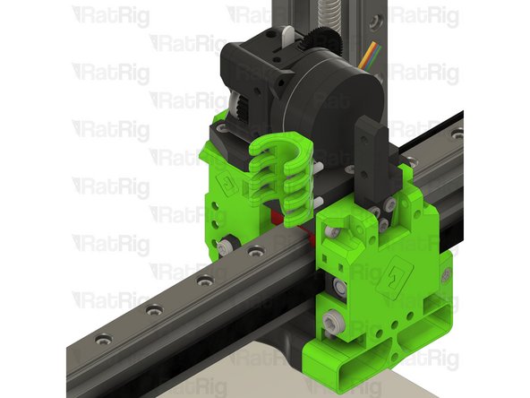
Assembly from Step 2
-
Place the EVA3 top assembly atop the MGN12 carriage as shown
-
Make sure the holes on the side of the printed part face towards the left of the x-axis
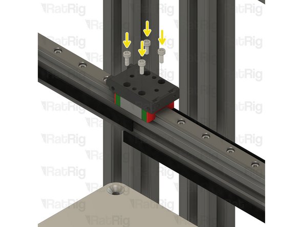
-
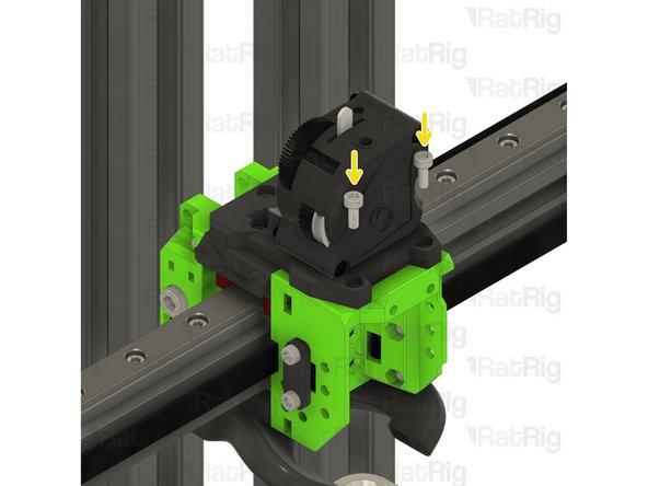
M3x8 Cap Head Screw
-
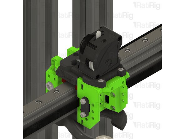
Fasten all four M3x8 screws to secure the EVA3 top assembly to the MGN12 carriage
-
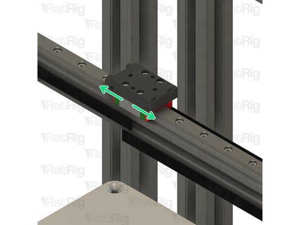
Slide the X-axis left and right along the rail to make sure it moves smoothly
-
If the carriage binds at all, slightly loosen the M3x8 screws and check again
-
-
-
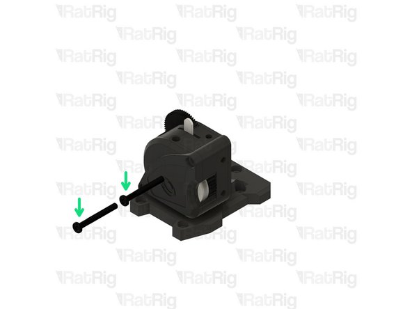
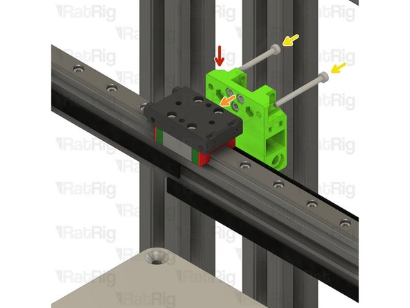
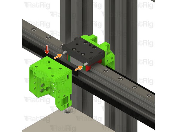
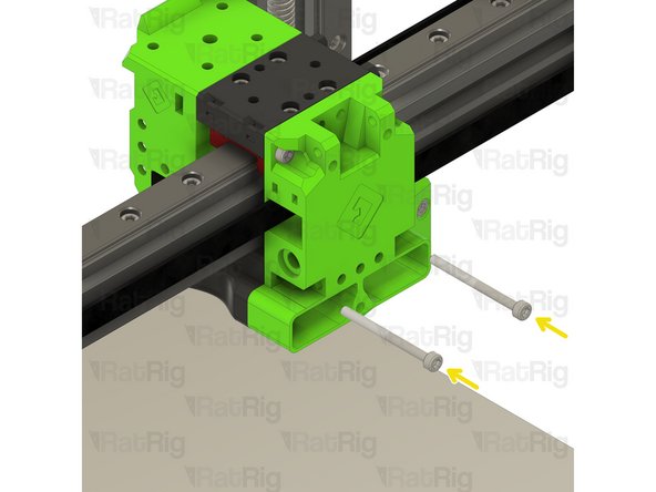
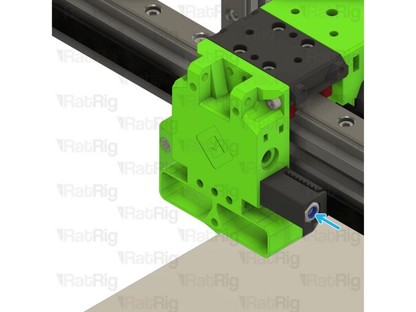
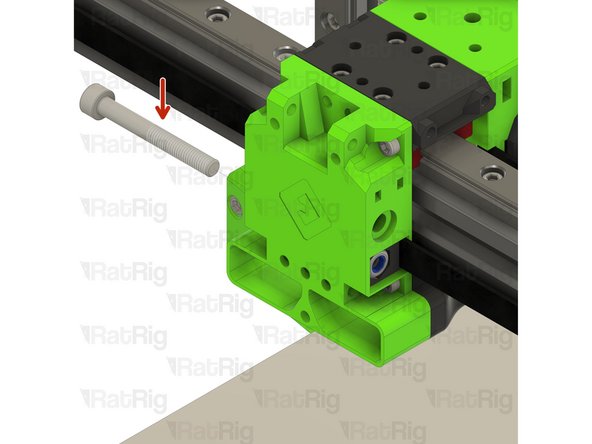
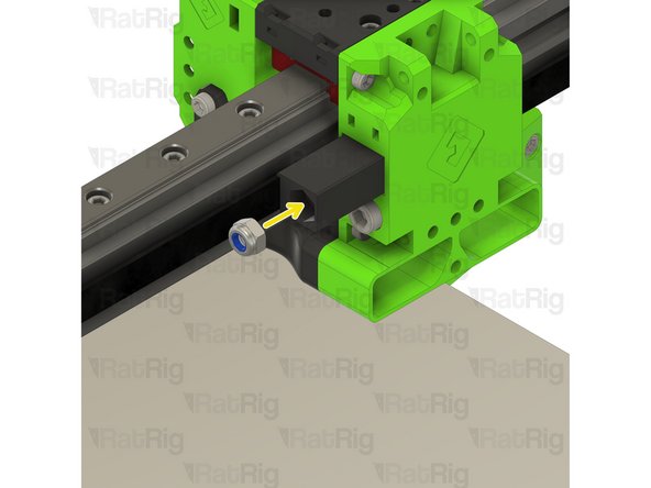
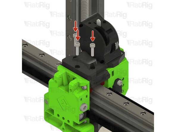
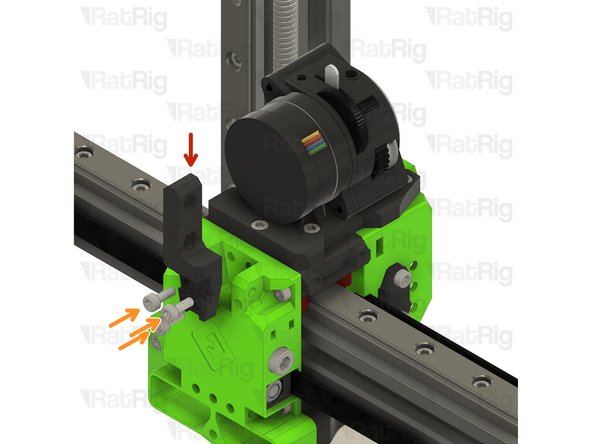
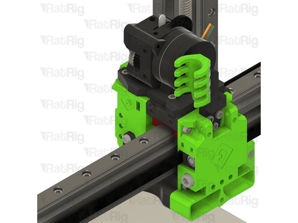
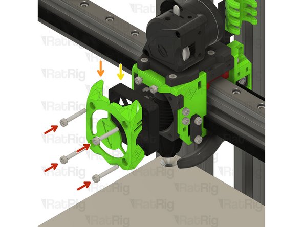
EVA3 back assembly from Step 6
-
Position the EVA3 back assembly as shown
-
M3x35 Cap Head Screw
-
Insert the M3x35 screws through the EVA3 back assembly and into the MGN12 mount as shown
-
-
-
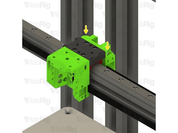
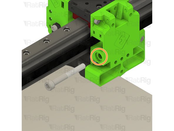
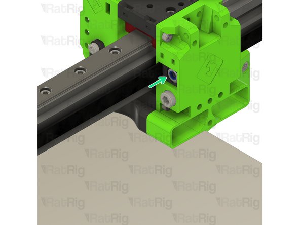
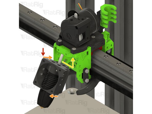
EVA3 front assembly from Step 5
-
Position the EVA3 front assembly as shown
-
Tighten the M3x35 screws to secure the EVA3 front assembly to the x-axis carriage
-
Take care not to over tighten the M3 screws as you can damage the printed parts
-
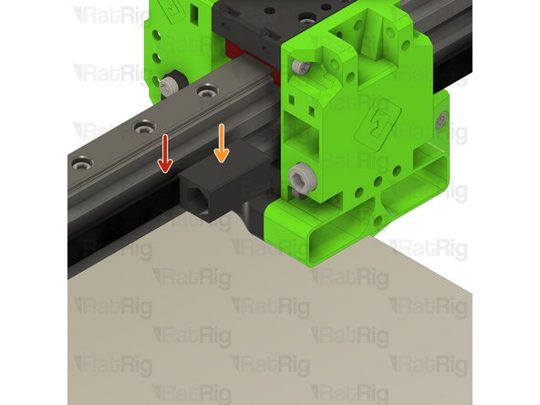
Take the end of the lower CoreXY belt and pass it through the side of the EVA3 front as shown
-
Pass the belt back out using the shown slot
-
Repeat these steps for the top CoreXY belt
-
The ends of both of these belts will be secured in Step 19
-
-
-
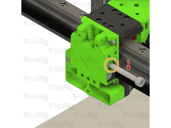
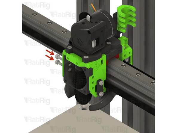
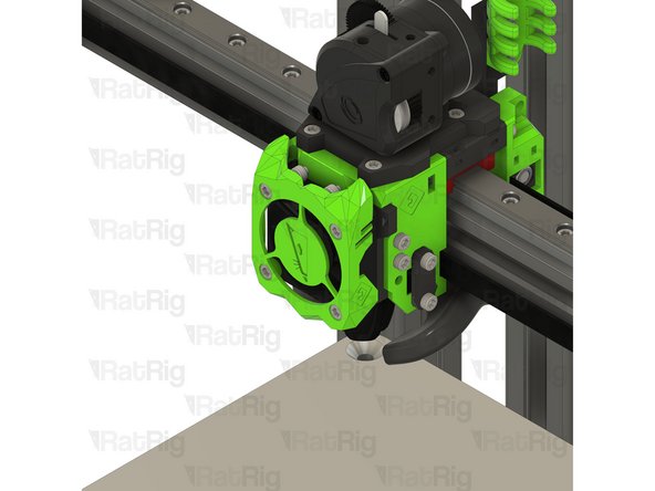
EVA3 bottom_horns_volcano Printed Part
-
Position the EVA3 bottom as shown
-
M3x35 Cap Head Screw
-
Install each M3x35 screw into the back, through the EVA3 bottom and secure them into the EVA3 front
-
Take care not to over tighten the M3 screws as you can damage the printed parts
-
-
-
2x EVA3 core_xy_belt_grabber Printed Part
-
3x M3x12 Cap Head Screw
-
2x M5 Nylon Locking Hex Nut
-
2x EVA3 face_belt_grabber Printed Part
-
6x M3x8 Cap Head Screw
-
2x M5x40 Cap Head Screw
-
-
-
Check that the CoreXY belt is still positioned from Step 16
-
Place the EVA3 face_belt_grabber printed part over the exposed belt end
-
Fasten two M3x8 screws through the EVA3 face_belt_grabber and into the universal face
-
Repeat the process on the left side of the EVA3 assembly
-
Take care not to over tighten the M3 screws as you can damage the printed parts
-
-
-
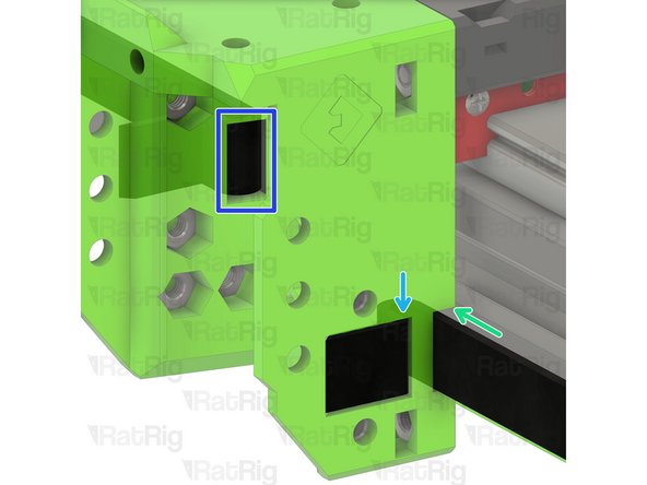
Loose end of the lower CoreXY belt
-
Mark the belt where it meets the EVA3 assembly. This can be with a marker, or simply by holding it.
-
From the mark, towards the loose end of the belt, measure 24mm (or count 12 teeth)
-
It is better to cut the belt too long than too short! If you are unsure, cut it longer than expected, you can always remove more if needed
-
Double check your measurements and then cut the belt at this point
-
Insert the cut end of the belt into the core_xy_belt_grabber printed part
-
Insert an M5 nylon locking nut into the core_xy_belt_grabber as shown
-
Insert the core_xy_belt_grabber assembly into the EVA3 assembly as shown
-
-
-
M5x40 Cap Head Screw
-
Insert the M5x40 screw into the marked hole on the EVA3 assembly and fasten it slightly to engage with the M5 nylon locking nut
-
Do not tighten the M5x40 screw at this point. The belts will be tensioned correctly in a later guide
-
-
-
Loose end of the upper CoreXY belt
-
As in Step 20, mark the belt where it meets the EVA3 assembly. This can be with a marker, or simply by holding it.
-
From the mark, towards the loose end of the belt, measure 24mm (or count 12 teeth)
-
It is better to cut the belt too long than too short! If you are unsure, cut it longer than expected, you can always remove more if needed
-
Double check your measurements and then cut the belt at this point
-
Insert the cut end of the belt into the core_xy_belt_grabber printed part
-
Insert an M5 nylon locking nut into the core_xy_belt_grabber as shown
-
Insert the core_xy_belt_grabber assembly into the EVA3 assembly as shown
-
-
-
M5x40 Cap Head Screw
-
Insert the M5x40 screw into the marked hole on the EVA3 assembly and fasten it slightly to engage with the M5 nylon locking nut
-
The M5x40mm screws are used to tighten the CoreXY belts
-
Tighten each M5x40 screw one-half turn at a time to tension the belts equally
-
Continue tightening the screws until the belts are no longer slack
-
Check that the X-axis gantry is square by moving it to the front of the machine. If it has skewed, it can be squared by adjusting the tension of one belt at a time
-
Make sure not to over-tension the belts as this can cause damage to the bearings, the belt, the motors or printed parts!
-
An excellent article on correct CoreXY belt tensioning is available on Mark Rehorst's website
-
-
-
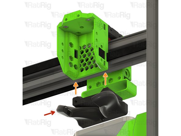
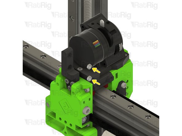
Bondtech LGX Lite assembly from Step 9
-
Place the Bondtech LGX Lite assembly onto the top of the EVA3 assembly as shown
-
M3x8 Cap Head Screw
-
Fasten the two M3x8 screws through the drive_lgx_lite printed part into the EVA3 universal front
-
Take care not to over tighten the M3 screws as you can damage the printed parts
-
-
-
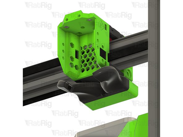
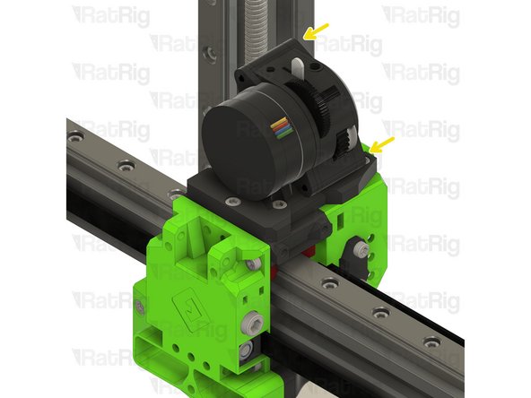
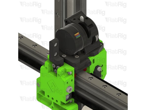
M3x12 Cap Head Screw
-
Fasten the three M3x12 screws through the drive_lgx_lite printed part into the EVA3 universal front
-
-
-
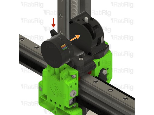
Bondtech LGX Lite motor from Step 7
-
Re-install the Bondtech LGX Lite motor into the back of the LGX Lite extruder
-
Fasten the two M3x25 screws on the face of the LGX Lite to secure the motor in place
-
-
-
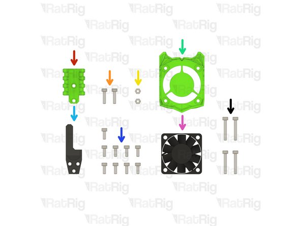
1x EVA3 cable_guide Printed Part
-
2x M3x12 Cap Head Screw
-
2x Hex Nut - M3
-
1x ratrig_eva3_shroud Printed Part
-
1x EVA3 cable_guide_mount Printed Part
-
9x M3x8 Cap Head Screw
-
1x 40x10mm 24V Axial Fan
-
4x M3x20 Cap Head Screw
-
-
-
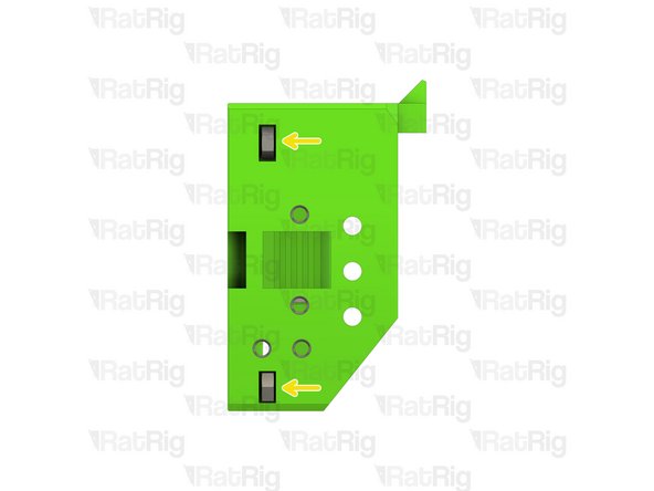
EVA3 cable_guide_mount Printed Part
-
M3x8 Cap Head Screw
-
Fasten the three M3x8 screws through the EVA3 cable_guide_mount printed part and into the EVA3 back
-
Hex Nut - M3
-
Install an M3 hex nut into each position as shown
-
-
-
EVA3 cable_guide Printed Part
-
M3x12 Cap Head Screw
-
Fasten the two M3x12 screws through the EVA3 cable_guide and into the EVA3 cable_guide_mount
-
-
-
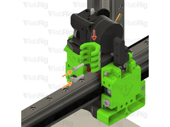
Phaetus Rapido UHF hot end assembly from Step 13
-
Angle the hot end assembly as shown
-
Guide the PTFE tube into hole in the top of the EVA3 universal front
-
Rotate the hot end assembly into position as shown
-
Check that the assembly is aligned correctly. The M3 hex nuts should be visible through the marked holes
-
-
-
M3x8 Cap Head Screw
-
Fasten the four M3x8 screws through the EVA3 universal front and into the hot end assembly to secure it in place
-
Take care not to over tighten the M3 screws as you can damage the printed parts
-
-
-
The ADXL module won't appear in the rest of the guide, as it only started being offered in V-Core 3.1 kits since October 2023
-
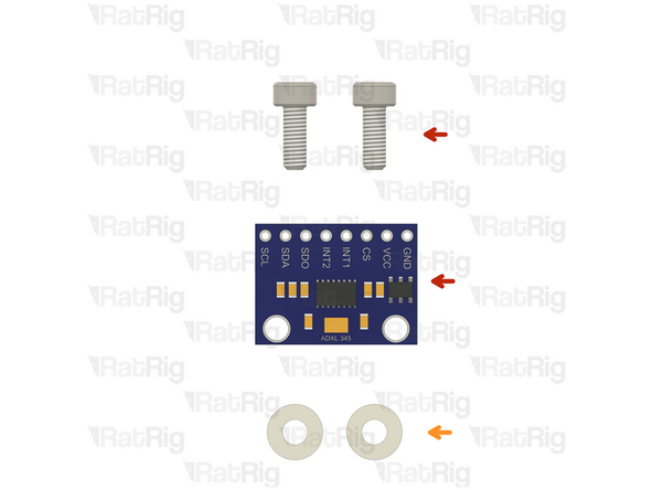
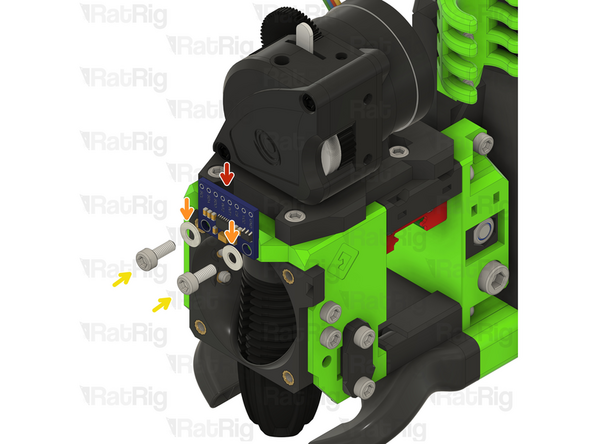
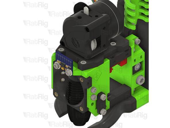
ADXL accelerometer module
-
Align the ADXL module with the two holes in the EVA assembly
-
2x M3 nylon washers
-
The nylon washers are required to prevent damaging the sensitive electronics on the ADXL board
-
2x M3x8 Cap Head Screw
-
Tighten the M3x8 screws to secure the ADXL in place
-
Do not overtighten the screws as the ADXL will be permanently damaged
-
-
-
M3x20 Cap Head Screw
-
ratrig_eva3_shroud Printed Part
-
40x10mm 24V Axial Fan
-
Insert the M3x20 screws into the ratrig_eva3_shroud, through the 40mm fan and fasten them into the EVA3 front
-
-
-
3x M3x8 Cap Head Screw
-
1x M3 Nylon Locking Hex Nut
-
1x EVA3 lj8_probe_mount Printed Part
-
1x Rat Rig SuperPinda Probe by P&F
-
-
-
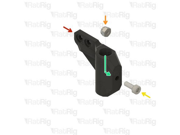
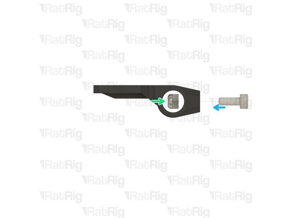
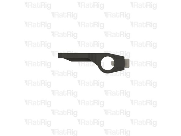
EVA3 lj8_probe_mount Printed Part
-
M3 Nylon Locking Hex Nut
-
M3x8 Cap Head Screw
-
The M3 nylon locking hex nut must be installed inside the lj8_probe_mount printed part
-
Fasten the M3x8 screw to pull the M3 nylon locking nut into position
-
-
-
EVA3 lj8_probe_mount assembly from the previous step
-
Position the probe mount assembly as shown
-
M3x8 Cap Head Screw
-
Fasten the two M3x8 screws through the probe mount and into the EVA3 assembly
-
Rat Rig SuperPinda Probe by P&F
-
Insert the probe into the probe mount as shown
-
-
-
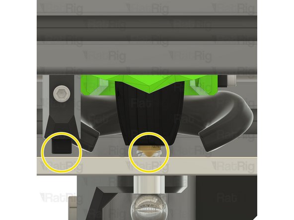
The Rat Rig SuperPinda Probe needs to be at the correct height to trigger properly
-
A recommended method to set the correct height is to rest the hot end nozzle on the bed, and then place a cable tie between the bed and the tip of the probe
-
Adjust the probe up to down as necessary to position the tip 1mm higher than the hot end nozzle
-
Tighten the M3x8 to secure the probe in place
-
Do not over-tighten the M3x8 screw, doing so can damage the probe or printed probe mount
-
Correct probe vs nozzle position
-
-
-
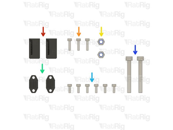
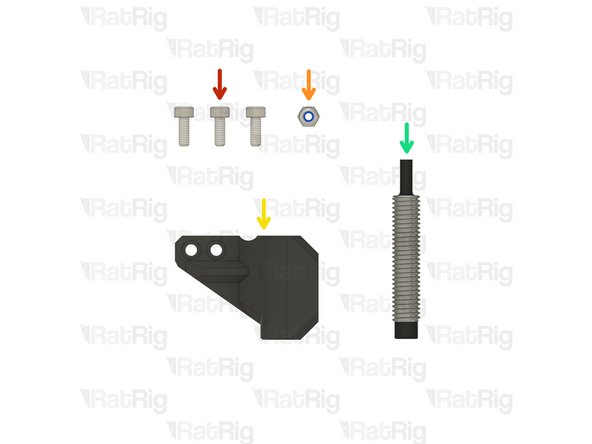
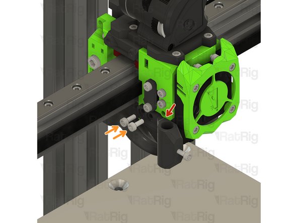
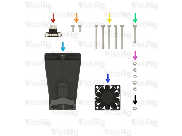
1x Endstop Module
-
2x M3x8 Cap Head Screw
-
5x M3x35 Cap Head Screw
-
1x M3x25 Cap Head Screw
-
1x EVA3 40mm_fan_inlet Printed Part
-
1x 4028 Part Cooling Fan
-
5x Hex Nut - M3
-
1x M3 Nylon Locking Hex Nut
-
-
-
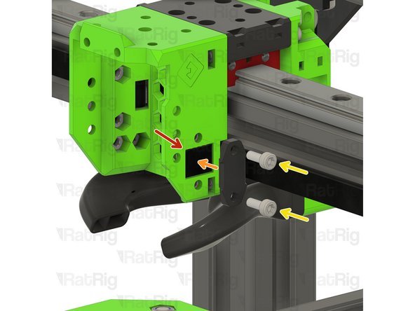
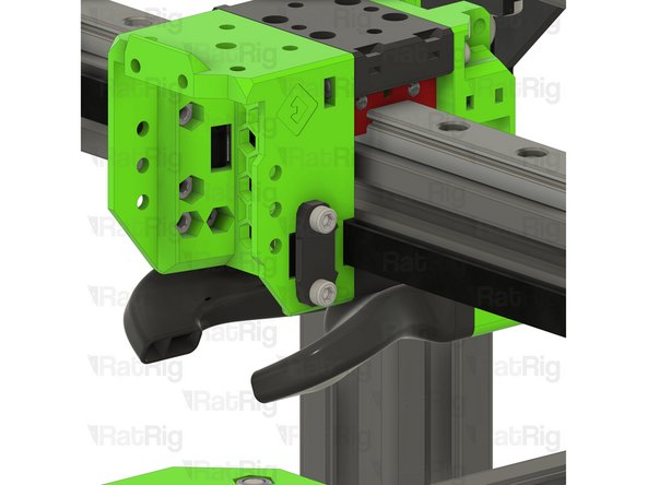
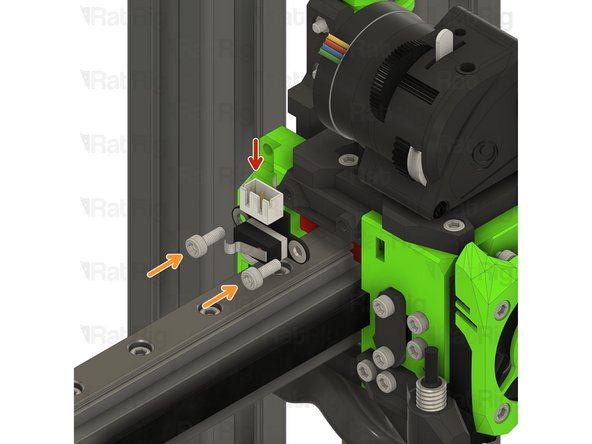
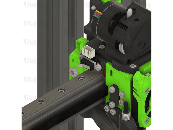
Endstop Module
-
M3x8 Cap Head Screw
-
Fasten the endstop module to the EVA3 assembly, as shown, using the M3x8 screws
-
These M3 screws fasten directly into the printed part. Take care not to over tighten them
-
-
-
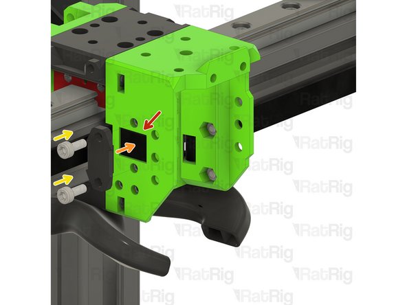
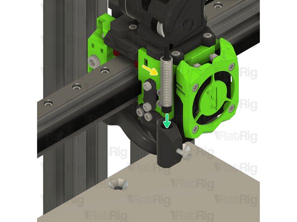
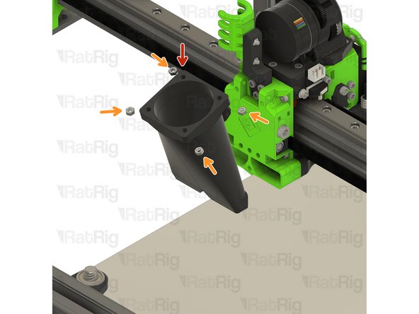
EVA3 40mm_fan_inlet Printed Part
-
Hex Nut - M3
-
Insert an M3 hex nut into the 40mm_fan_inlet as shown
-
Fully install the M3 hex nut up and into the 40mm_fan_duct as shown
-
Repeat the process for the other three M3 hex nuts
-
-
-
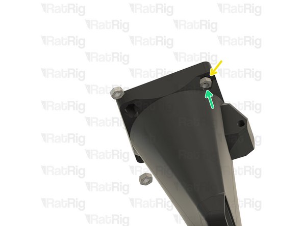
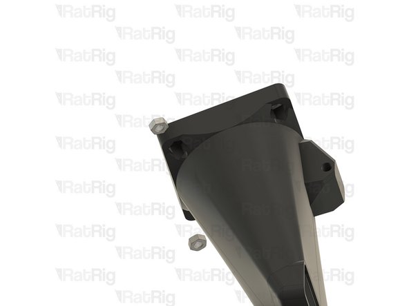
EVA3 40mm_fan_inlet assembly
-
4028 Part Cooling Fan
-
M3x35 Cap Head Screw
-
Fasten the four M3x35 screws through the 4028 cooling fan and into the hex nuts within the 40mm_fan_inlet
-
M3x35 Cap Head Screw
-
This M3x35 screw will be used in the next step to secure the 40mm_fan_inlet to the EVA3 assembly
-
-
-
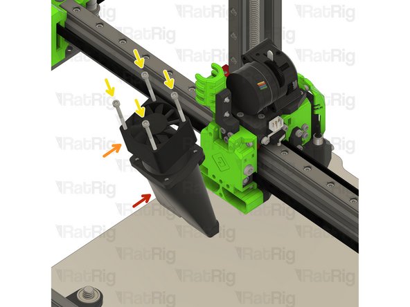
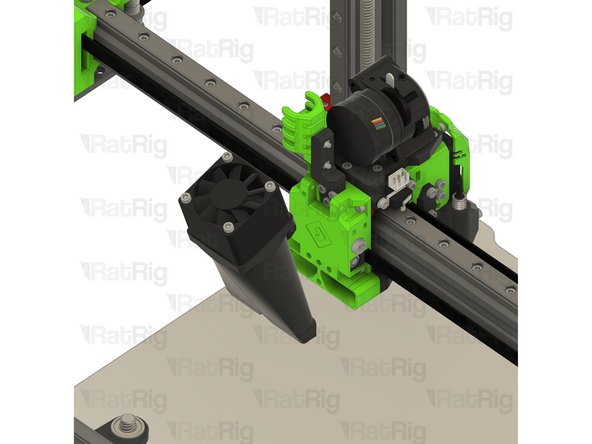
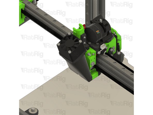
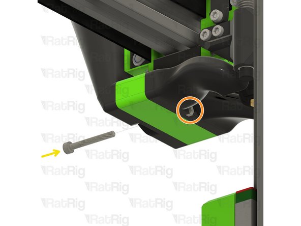
Install the 40mm_fan_duct assembly as shown
-
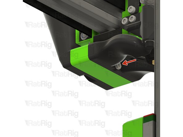
Push the M3x35 screw though the EVA3 assembly and 40mm_fan_duct as shown
-
The tip of the M3x35 screw should extend out of the EVA3 assembly as shown
-
M3 Nylon Locking Hex Nut
-
Fasten the M3 nylon hex nut onto the M3x35 screw
-
-
-
Hex Nut - M3
-
Position the M3 hex nut as shown
-
M3x25 Cap Head Screw
-
Fasten the M3x25 screw through the 40mm_fan_duct and into the M3 hex nut
-
Take care not to over tighten the M3 screw as you can damage the printed parts
-


Cancel: I did not complete this guide.
26 other people completed this guide.