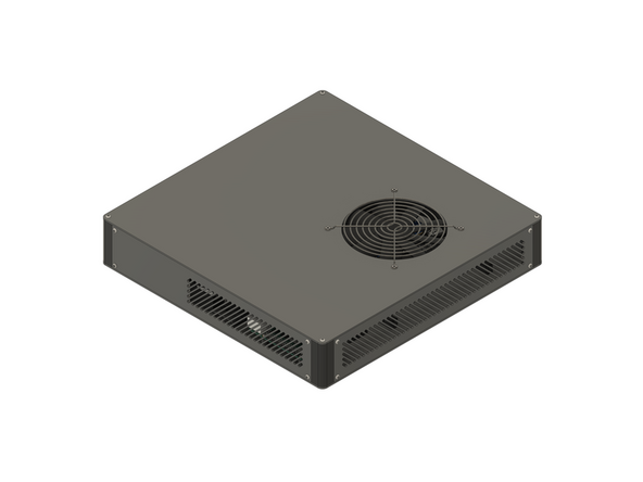
Introduction
This section of the guide will step you through preparing and assembling all of the components used in the V-Core 4.0 electronics enclosure.
-
-
The following tools are required for this guide:
-
Allen key / hex wrenches in the following sizes: 2mm, 2.5mm & 5mm
-
Spanners / wrenches in the following sizes: 5.5mm, 7mm, 10mm & 15mm
-
The following tools are recommended for this guide:
-
A slim 7mm hex socket and ratchet, or 7mm socket driver
-
-
-
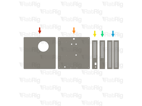
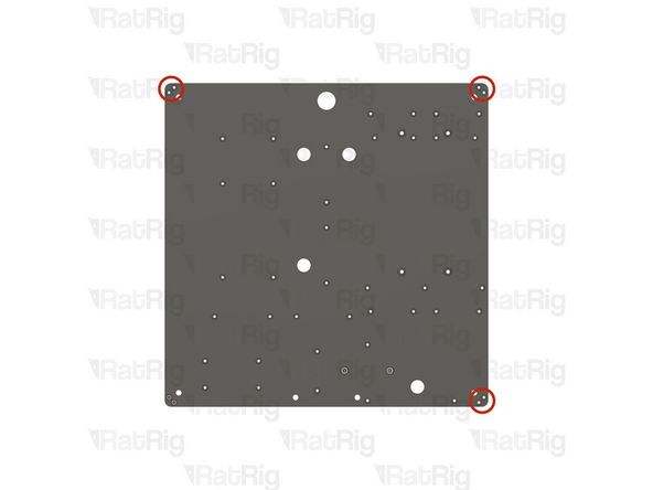
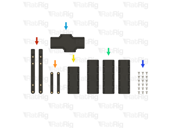
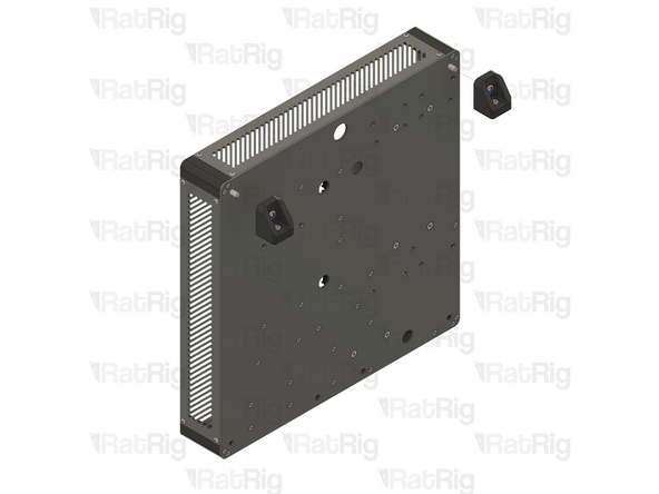
The six panels for the V-Core 4.0 aluminium electronics enclosure are provided as a single pack (SKU: HW3944GC)
-
1x Lid panel
-
1x Base panel
-
1x IEC inlet panel
-
1x Bottom vent panel
-
2x Top / Side vent panels
-
-
-
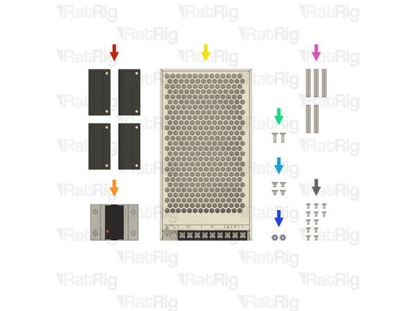
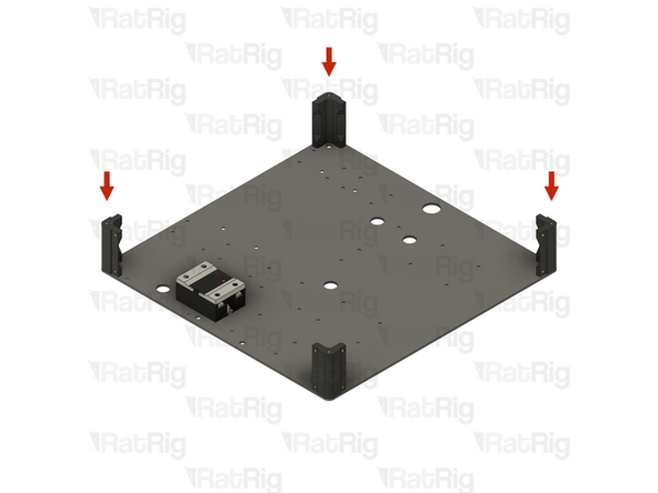
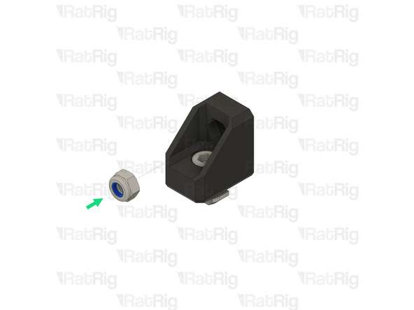
4x vc4_electronics_1.2_corner assemblies (SKU: PP000352)
-
1x 40A Solid State Relay (SKU: HW1733EC)
-
1x 250W 24V Fanless Power Supply (SKU: HW1351EC)
-
2x M4x12 Countersink Screw (SKU: HW3259SC)
-
4x M4x6 Countersink Screw (SKU: HW3777SC)
-
2x M4 Locking Hex Nut (SKU: HW1374NC)
-
5x M3 Hex Standoff - 35mm (SKU: HW3935NC)
-
13x M3x6 Countersink Screw (SKU: HW3414SC)
-
-
-
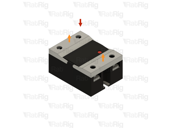
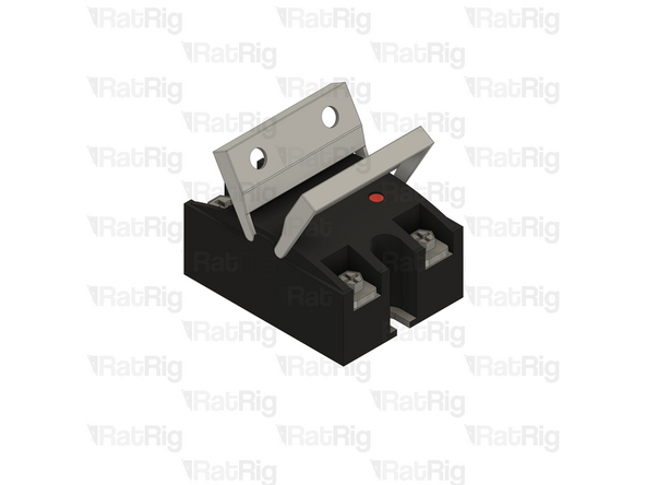
1x 40A Solid State Relay
-
The Solid State Relay has a plastic guard on each end. These must be rotated upwards as shown
-
-
-
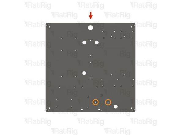
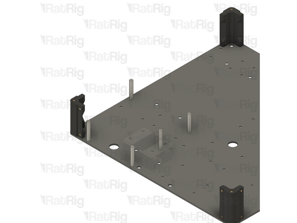
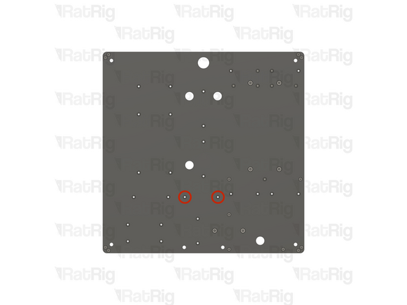
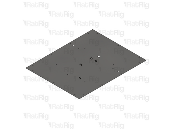
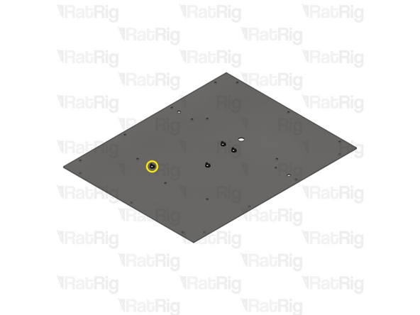
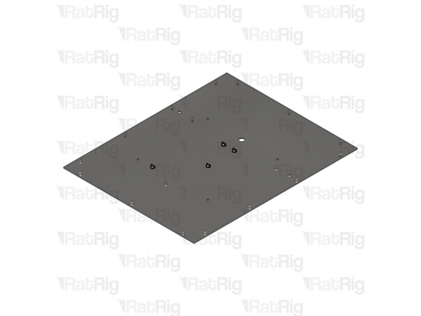
1x Electronics enclosure base panel
-
Locate the two marked holes in the base panel
-
2x M4x12 Countersink Screw
-
Insert an M4x12 Countersink Screw into each marked hole
-
When correctly installed, the screw heads should be flat with the panel
-
-
-
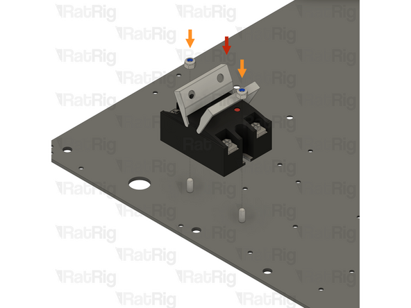
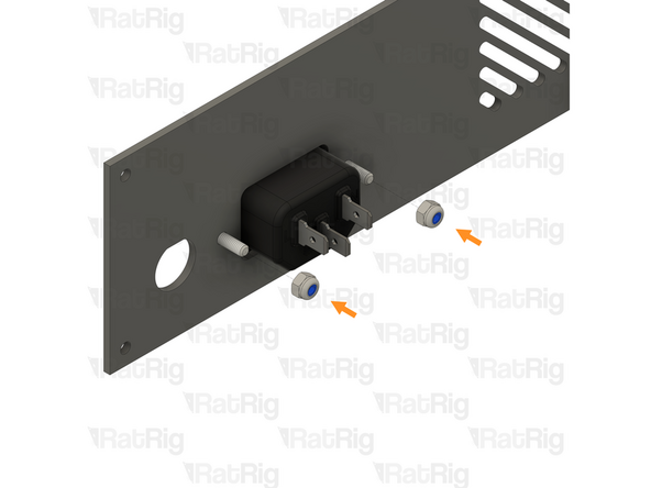
1x 40A Solid State Relay
-
The Solid State Relay has a high voltage and low voltage side, and needs to be oriented correctly
-
Make sure that the red LED indicator on the Solid State Relay faces towards the right hand side of the panel
-
2x M4 Locking Hex Nut
-
Install an M4 Locking Hex Nut onto each M4x12 screw as shown
-
It is recommended, and easier, to use a 7mm socket driver or a slim 7mm hex socket and ratchet to tighten the M4 Locking Hex Nuts
-
It is also possible to use a flat head screwdriver, or needle-nose pliers, to prevent the nut from turning whilst tightening the screws
-
-
-
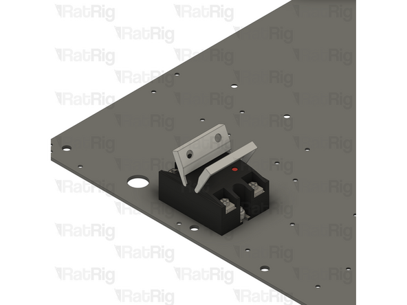
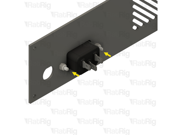
Close the plastic guards on the Solid State Relay
-
Verify the orientation of the Solid State Relay before continuing
-
Make sure that the red LED indicator on the Solid State Relay faces towards the right hand side of the panel
-
-
-
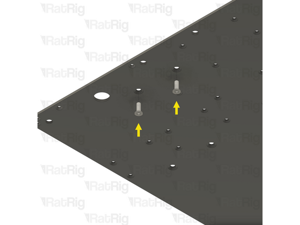
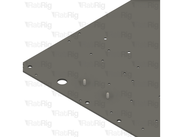
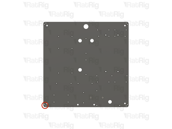
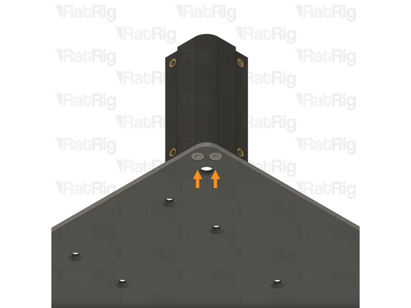
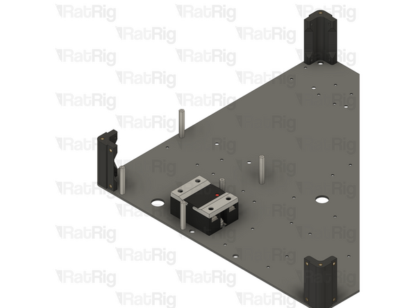
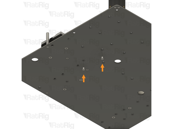
Locate the two marked holes in the base panel
-
2x M3x6 Countersink Screw
-
Insert an M3x6 Countersink Screw into each of the marked holes
-
-
-
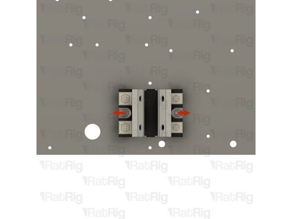
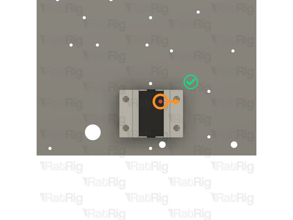
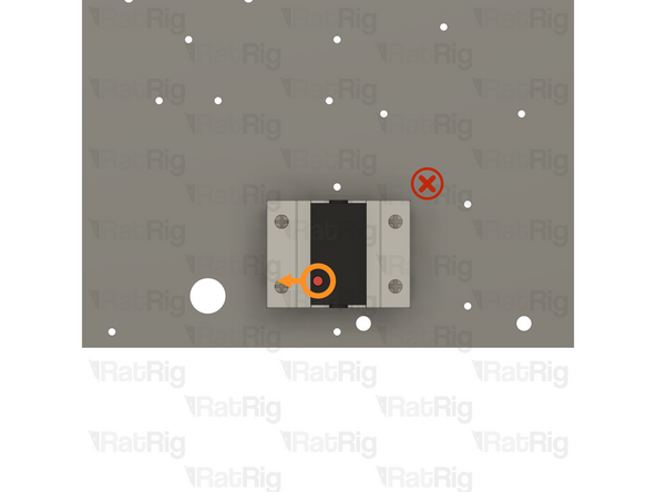
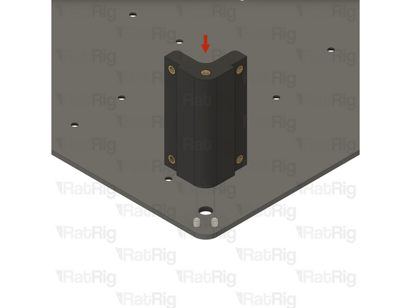
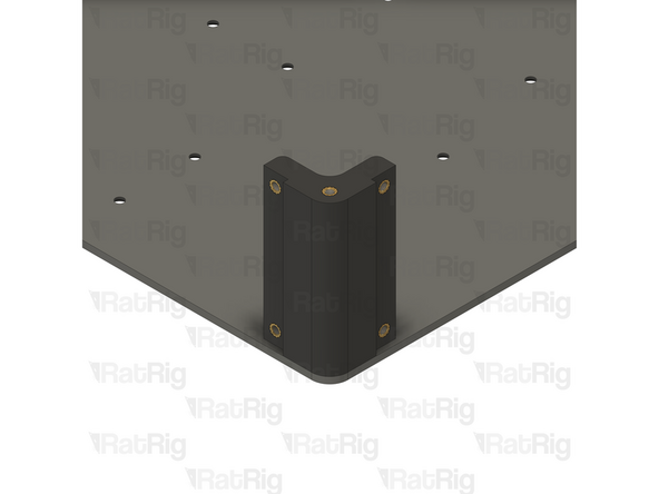
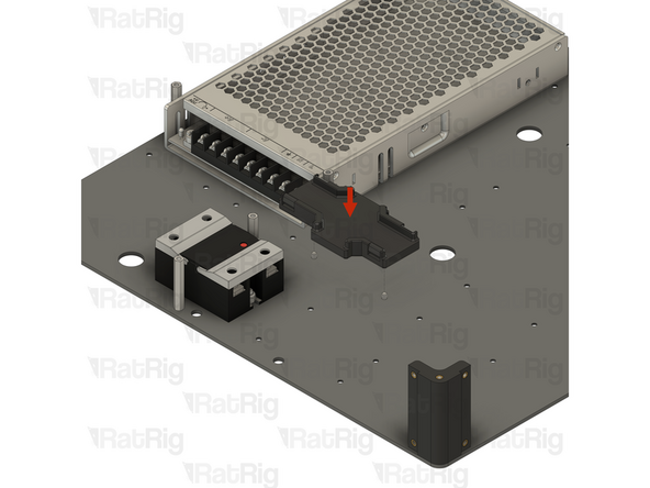
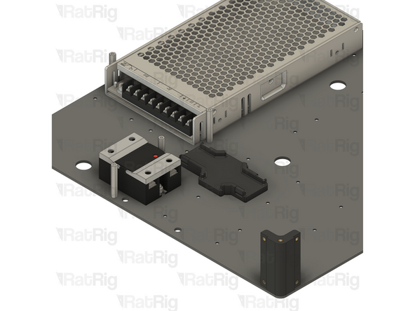
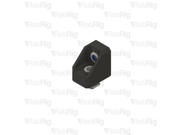
1x vc4_electronics_1.2_corner assembly
-
Tighten both M3x6 Countersink Screws to secure the corner assembly to the base panel
-
Be careful not to overtighten the screws as you can damage the printed parts
-
-
-
-
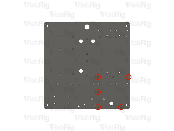
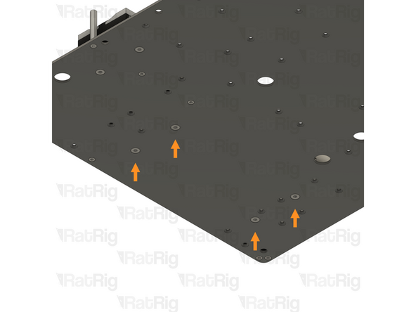
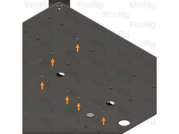
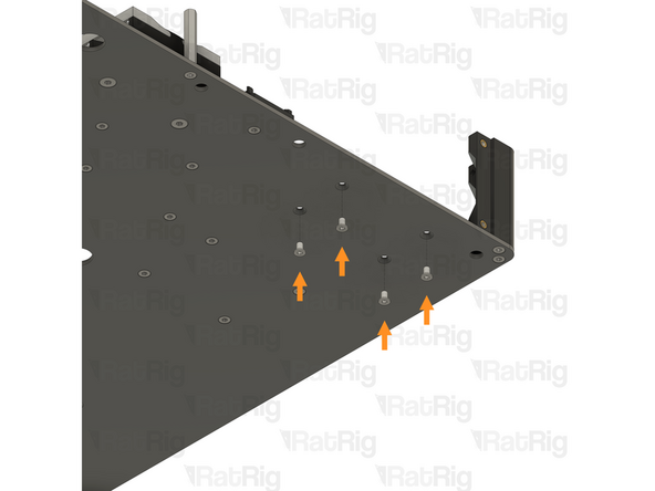
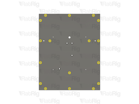
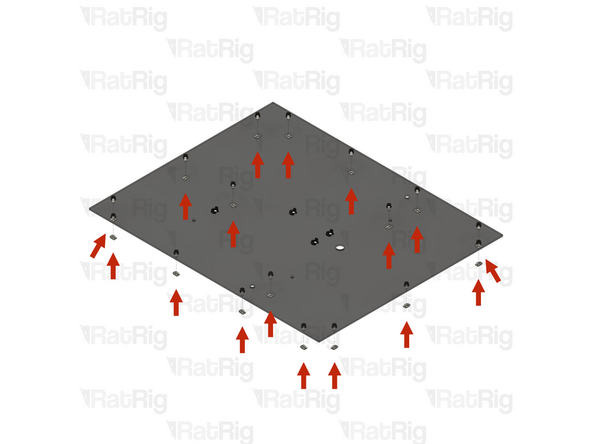
Locate the five marked holes in the base panel
-
5x M3x6 Countersink Screw
-
Insert an M3x6 Countersink Screw into each of the marked holes
-
-
-
In this step, the Solid State Relay has been faded out to avoid obscuring the instructions
-
5x M3 Hex Standoff - 35mm
-
Thread a Hex Standoff onto each of the five M3 Countersink Screws as shown and tighten them
-
-
-
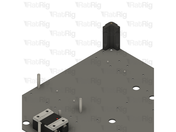
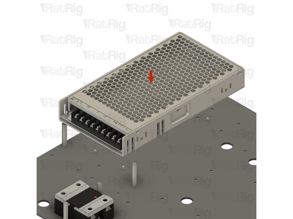
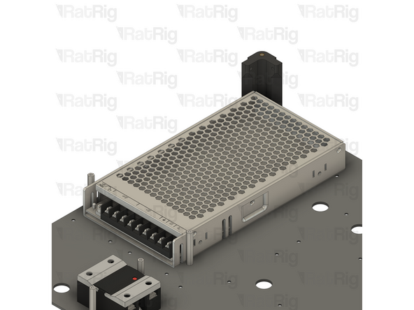
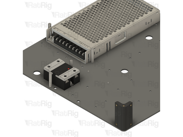
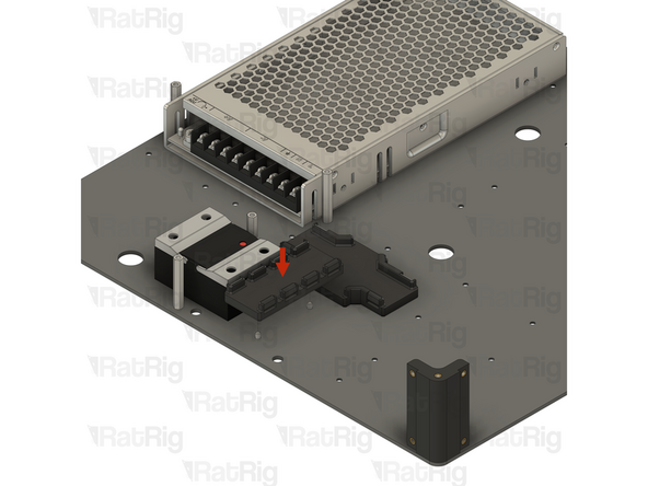
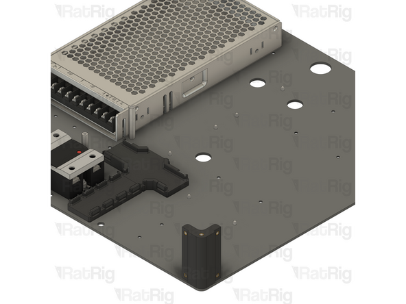
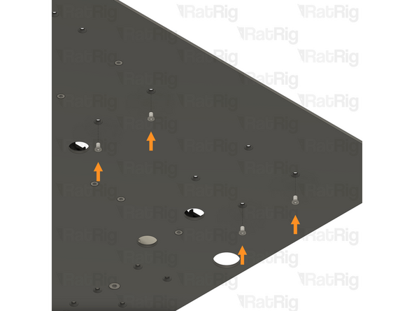
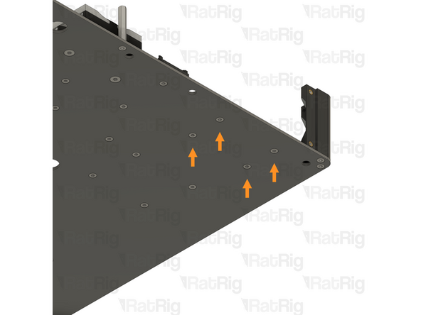
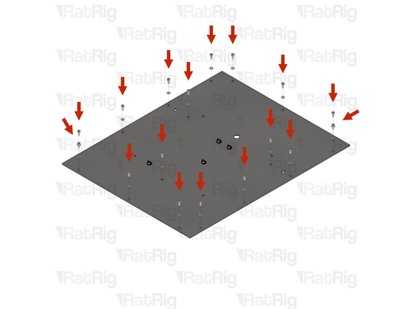
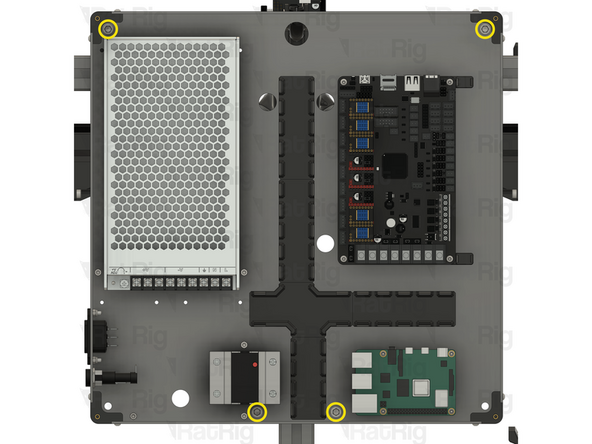
Locate the four marked holes in the base panel
-
4x M4x6 Countersink Screw
-
Insert an M4x6 Countersink Screw into each of the marked holes
-
-
-
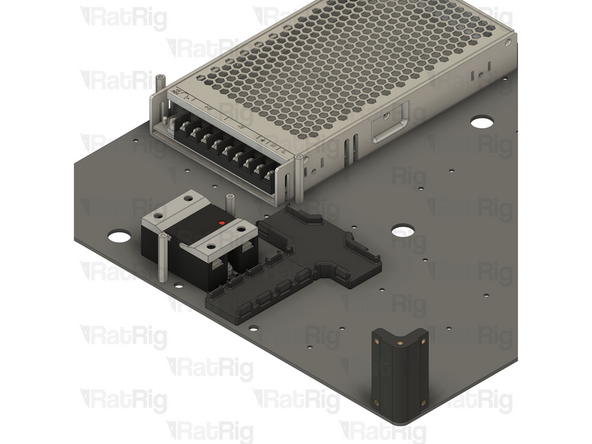
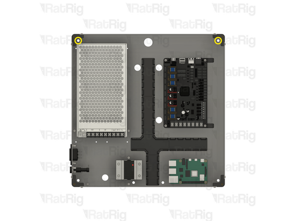
1x 250W 24V Fanless power supply
-
Tighten all four M4x6 Countersink Screws to secure the power supply to the base panel
-
-
-
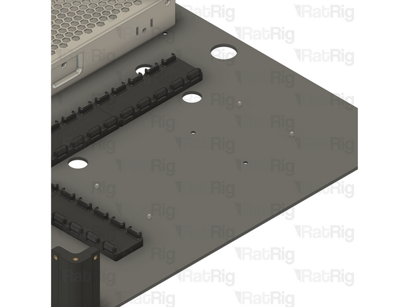
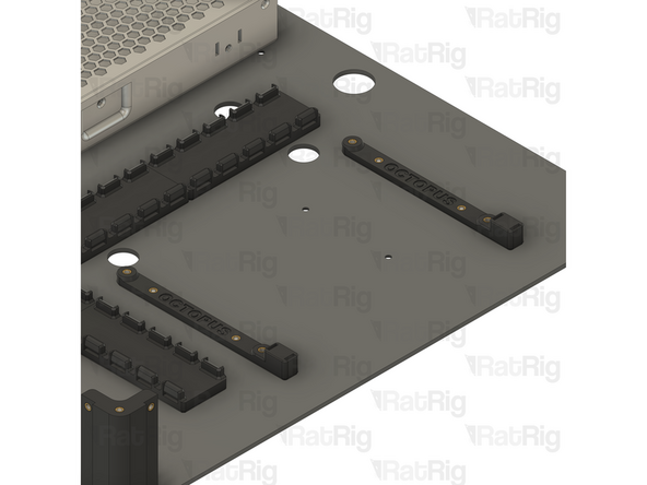
2x vc4_adapter_octopus (SKU: PP000301)
-
2x vc4_adapter_rpi (SKU: PP000302)
-
1x vc4_cable_guide_4 (SKU: PP000304)
-
3x vc4_cable_guide_5 (SKU: PP000305)
-
1x vc4_cable_guide_cross (SKU: PP000306)
-
18x M3x6 Countersink Screw (SKU: HW3414SC)
-
-
-
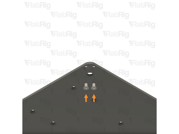
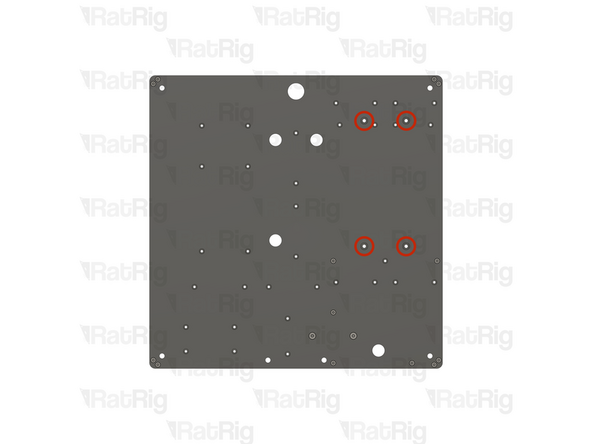
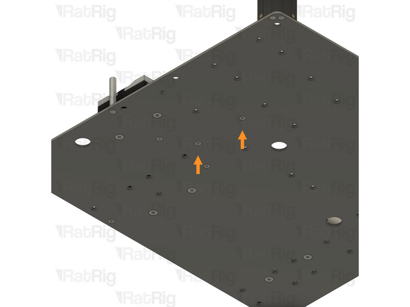
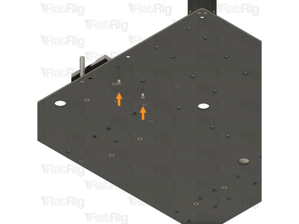
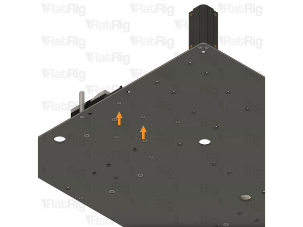
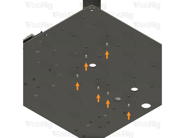
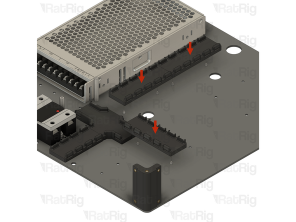
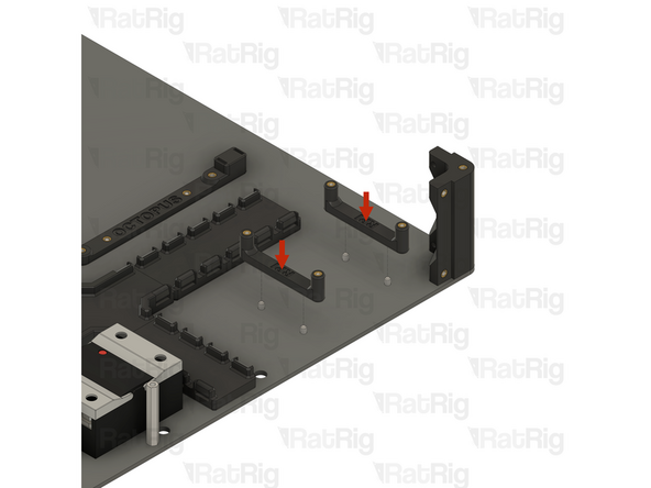
Locate the two marked holes in the base panel
-
2x M3x6 Countersink Screw
-
Insert an M3x6 Countersink Screw into each of the marked holes
-
-
-
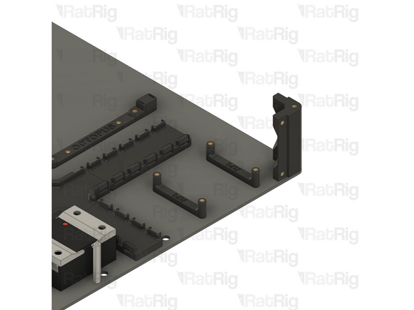
1x vc4_cable_guide_cross
-
Tighten both M3x6 Countersink Screws to secure the cable guide to the base panel
-
Be careful not to overtighten the screws as you can damage the printed parts
-
-
-
Locate the two marked holes in the base panel
-
2x M3x6 Countersink Screw
-
Insert an M3x6 Countersink Screw into each of the marked holes
-
-
-
1x vc4_cable_guide_4
-
Tighten both M3x6 Countersink Screws to secure the cable guide to the base panel
-
Be careful not to overtighten the screws as you can damage the printed parts
-
-
-
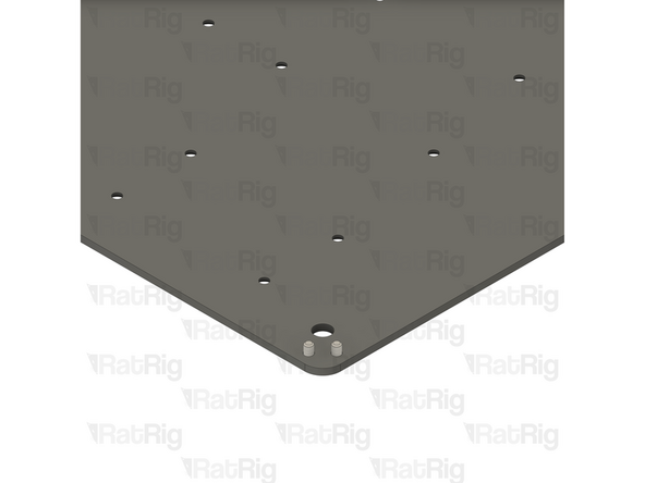
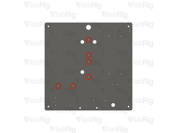
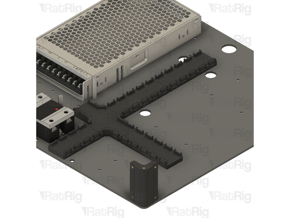
Locate the six marked holes in the base panel
-
6x M3x6 Countersink Screw
-
Insert an M3x6 Countersink Screw into each of the marked holes
-
-
-
3x vc4_cable_guide_5
-
Tighten all six M3x6 Countersink Screws to secure the cable guides to the base panel
-
Be careful not to overtighten the screws as you can damage the printed parts
-
-
-
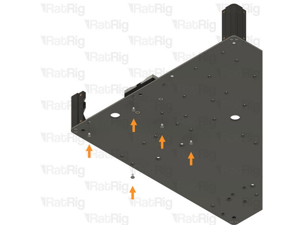
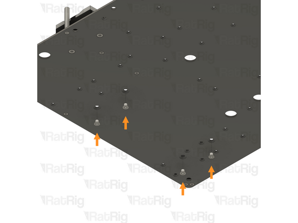
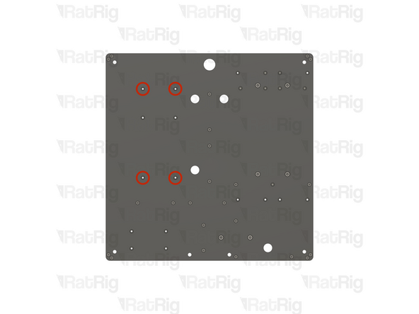
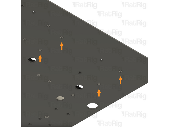
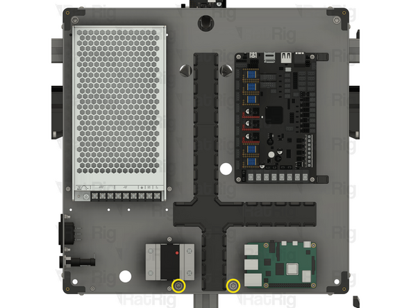
Locate the four marked holes in the base panel
-
4x M3x6 Countersink Screw
-
Insert an M3x6 Countersink Screw into each of the marked holes
-
-
-
2x vc4_adapter_octopus
-
Tighten all four M3x6 Countersink Screws to secure the cable guides to the base panel
-
Be careful not to overtighten the screws as you can damage the printed parts
-
-
-
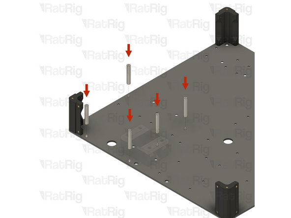
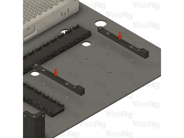
Locate the four marked holes in the base panel
-
4x M3x6 Countersink Screw
-
Insert an M3x6 Countersink Screw into each of the marked holes
-
-
-
2x vc4_adapter_rpi
-
Tighten all four M3x6 Countersink Screws to secure the cable guides to the base panel
-
Be careful not to overtighten the screws as you can damage the printed parts
-
Set this assembly aside until step 34
-
-
-
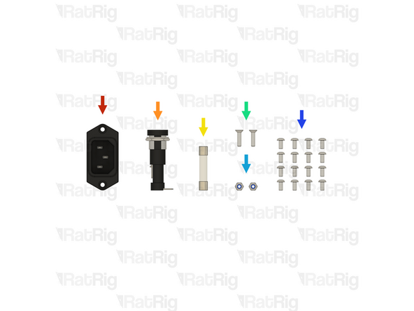
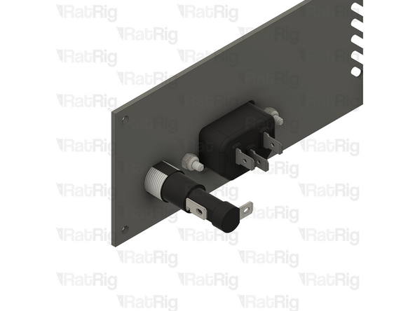
1x IEC Socket - Schurter 6100.3200 (SKU: HW3957EC)
-
1x Fuse Holder - EATON BK2-HTJ-608I (SKU: HW3958EC)
-
1x Fuse - 6.3x32mm Time-Lag 15A (SKU: HW3959EC)
-
2x M3x12 Countersink Screw (SKU: HW1874SC)
-
2x M3 Locking Hex Nut (SKU: HW1251NC)
-
16x M3x6 Button Head Screw (SKU: HW1337SC)
-
-
-
-
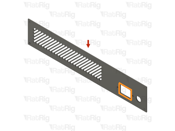
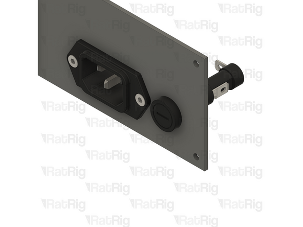
1x IEC inlet panel from step 2
-
Make sure the panel is oriented as shown, with the rectangular hole at the bottom
-
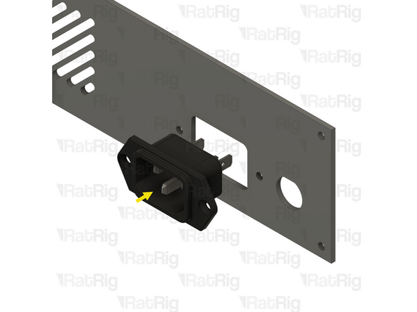
1x IEC Socket - Schurter 6100.3200
-
Insert the IEC socket into the panel as shown
-
Make sure that the middle pin of the IEC socket is at the bottom
-
-
-
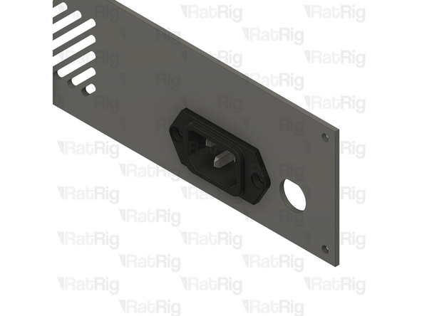
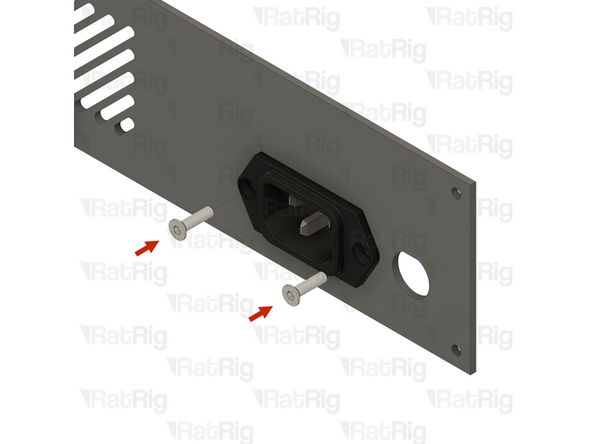
2x M3x12 Countersink Screw
-
Insert an M3x12 Countersink Screw into each of the holes on the IEC socket and through the panel
-
2x M3 Locking Hex Nut
-
Install an M3 Locking Hex Nut onto each of the M3x12 screws and tighten them to secure the IEC socket to the panel
-
The M3 Locking Hex Nuts can be held with a 5.5mm spanner, wrench or socket
-
-
-
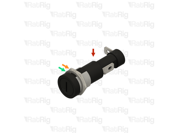
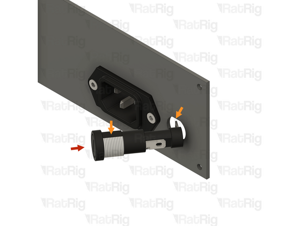
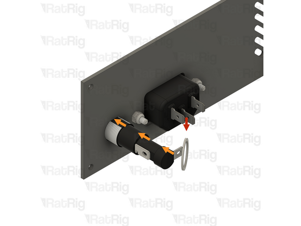
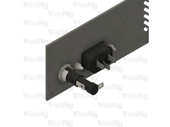
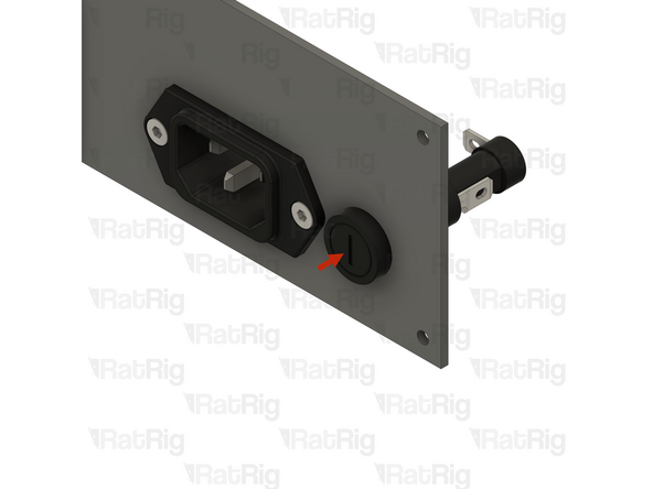
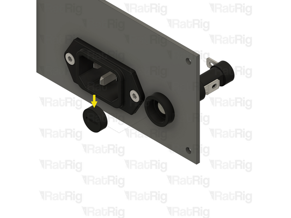
1x Prepared Fuse Holder from step 27
-
Rotate the fuse holder, so the flat surface is aligned with the flat on the panel cutout
-
Angle the fuse holder and insert it into the panel as shown
-
-
-
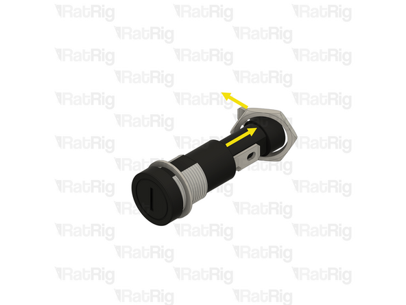
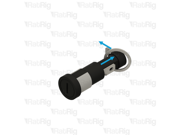
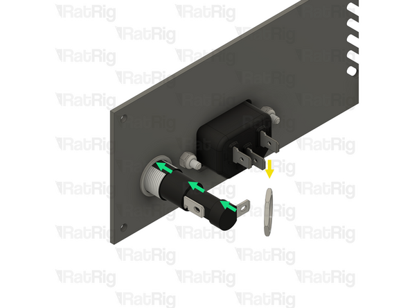
1x Fuse Holder Washer from step 27
-
Slide the washer back onto the fuse holder body, positioning it next to the panel as shown
-
1x Fuse Holder Retaining Nut from step 27
-
Slide the retaining nut back onto the fuse holder body as shown
-
Holding the fuse holder, to prevent it from spinning, tighten the retaining nut onto the threaded section to secure the fuse holder to the panel
-
Using excessive force to tighten the retaining nut can damage the plastic threads on the fuse holder
-
-
-
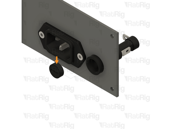
1x Fuse Holder Cap
-
Use a flat head screwdriver to open the fuse holder by turning it a quarter turn counterclockwise
-
Set the cap aside for the next step
-
-
-
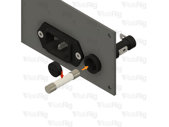
1x Fuse - 6.3x32mm time-lag 15A
-
Insert the fuse fully into the holder, as shown
-
1x Fuse Holder Cap
-
Insert the cap into the fuse holder and secure it by turning it a quarter turn clockwise with a flat head screwdriver
-
Set this assembly aside until step 35
-
-
-
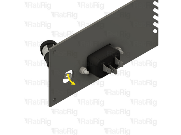
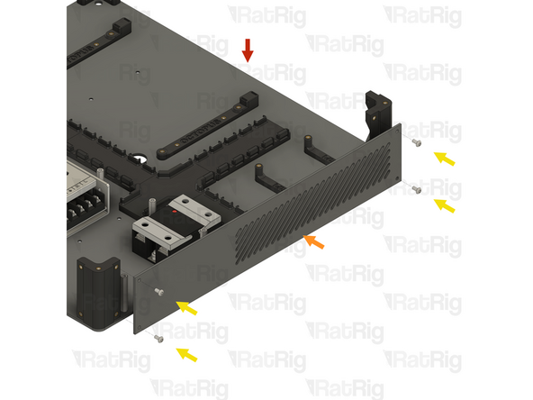
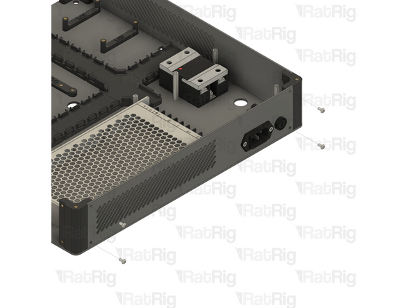
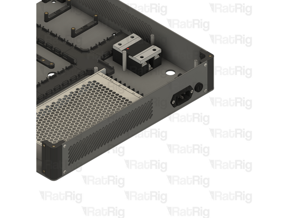
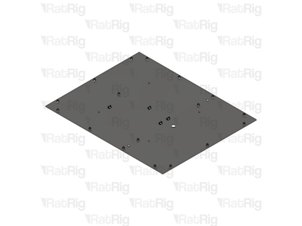
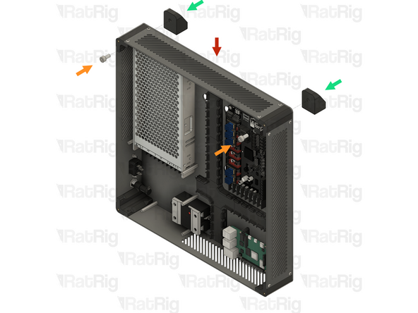
1x Electronics enclosure assembly from step 25
-
1x Bottom vent panel from step 2
-
Align the bottom vent panel as shown, making sure the vented section is on the right hand side
-
4x M3x6 Button Head Screw
-
Tighten all four M3x6 Button Head Screws to secure the panel to the base enclosure assembly
-
Be careful not to overtighten the screws as you can damage the printed parts
-
-
-
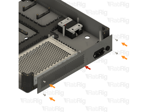
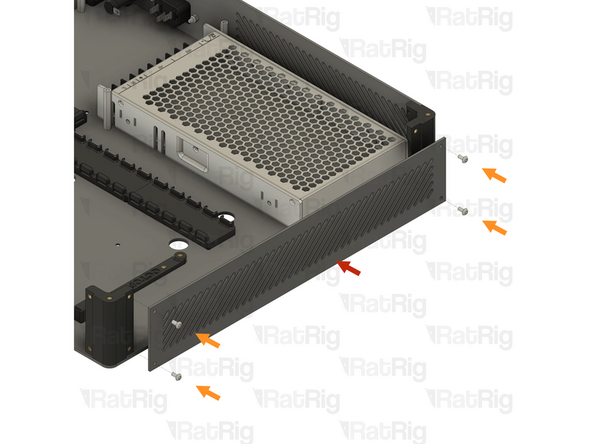
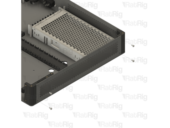
1x IEC inlet panel assembly from step 33
-
Align the IEC inlet panel as shown, making sure the IEC inlet is on the right-hand side
-
4x M3x6 Button Head Screw
-
Tighten all four M3x6 Button Head Screws to secure the panel to the base enclosure assembly
-
Be careful not to overtighten the screws as you can damage the printed parts
-
-
-
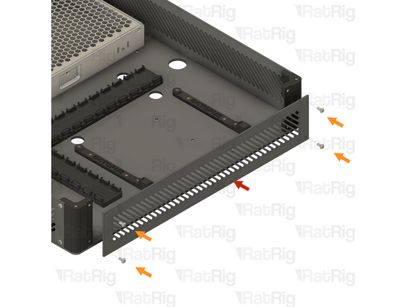
1x Top / side vent panel from step 2
-
Align the top vent panel as shown
-
4x M3x6 Button Head Screw
-
Tighten all four M3x6 Button Head Screws to secure the panel to the base enclosure assembly
-
Be careful not to overtighten the screws as you can damage the printed parts
-
-
-
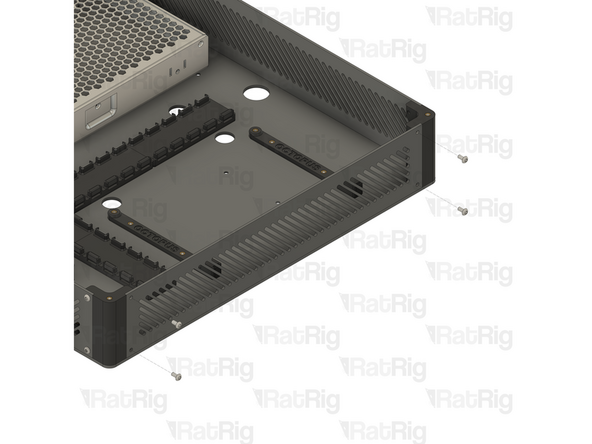
1x Top / side vent panel from step 2
-
Align the top vent panel as shown
-
4x M3x6 Button Head Screw
-
Tighten all four M3x6 Button Head Screws to secure the panel to the base enclosure assembly
-
Be careful not to overtighten the screws as you can damage the printed parts
-
Set the electronics enclosure assembly aside until step 48
-
-
-
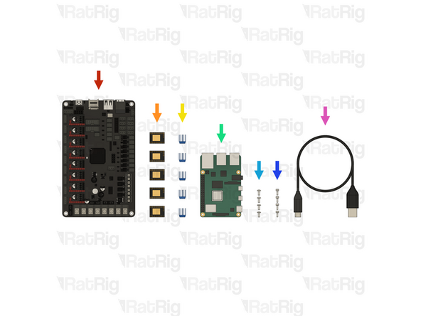
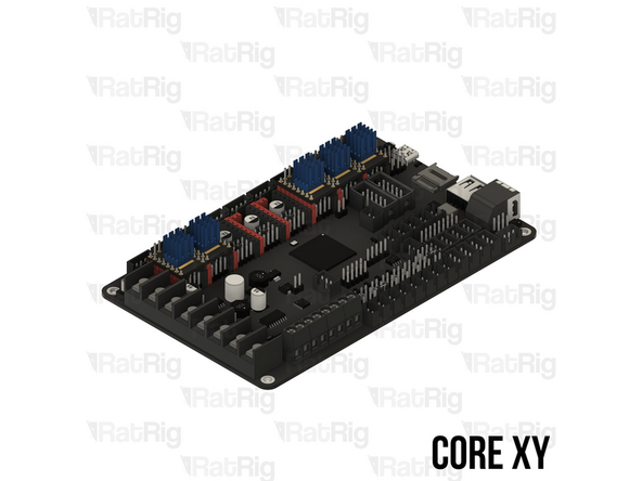
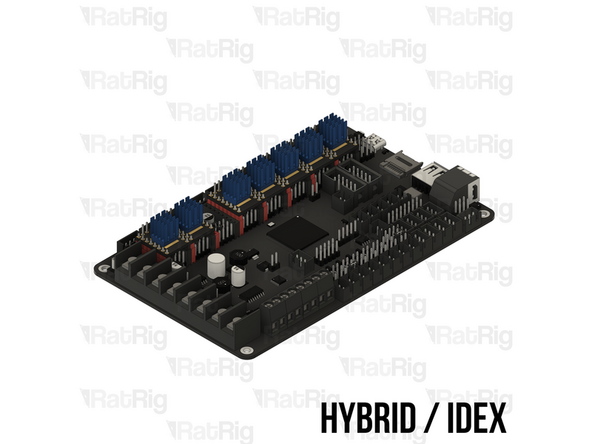
1x BIGTREETECH Octopus v1.1 motherboard (SKU: HW2832EC)
-
5x BIGTREETECH TMC2209 Stepper driver (SKU: HW2052EC)
-
5x Blue anodised heatsink (Included in the stepper driver box)
-
If you are building a Hybrid or IDEX variant of the V-Core 4.0, you need seven drivers and heatsinks instead of five
-
1x Raspberry Pi model 4B - 1GB (SKU: HW3790EC)
-
4x M3x6 Button Head Screw (SKU: HW1337SC)
-
4x M2.5x6 Cap Head Screw (SKU: HW3775SC)
-
1x USB-A to USB-C cable (Included in the Octopus v1.1 box)
-
-
-
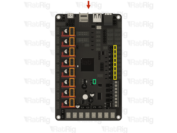
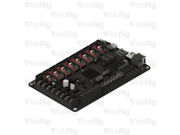
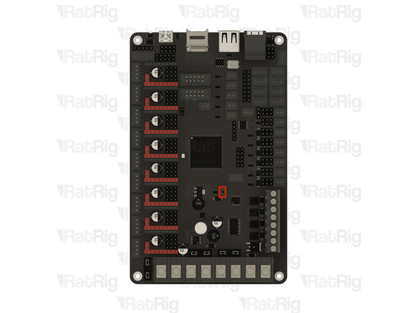
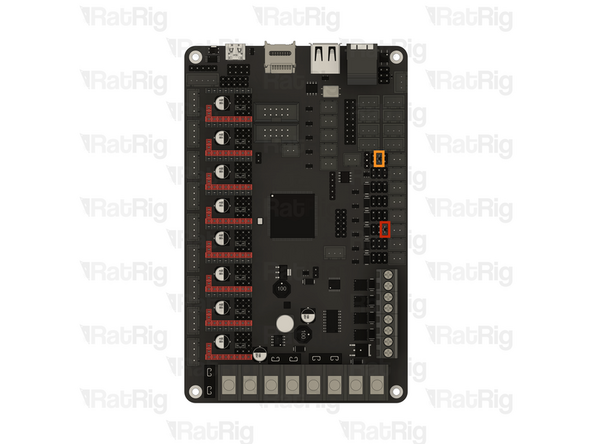
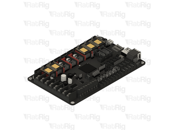
1x BIGTREETECH Octopus v1.1 motherboard
-
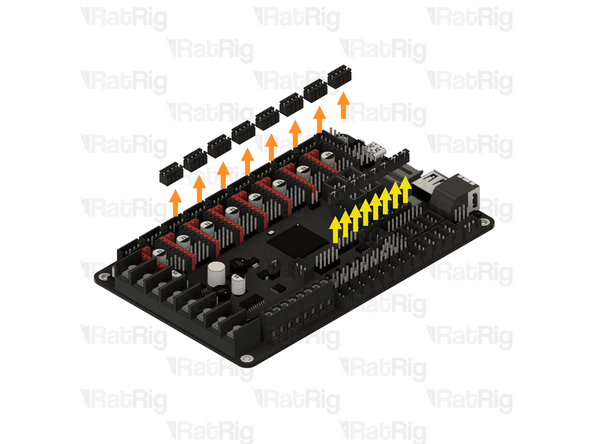
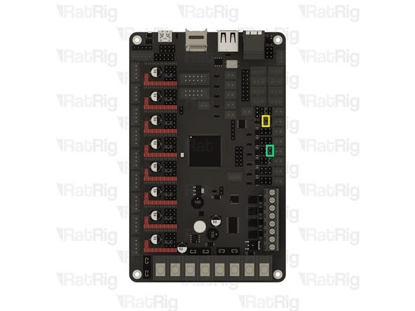
The Octopus motherboard is provided with jumpers preinstalled which need to be removed
-
Stepper driver configuration jumpers
-
Remove all thirty-two jumpers and set them aside
-
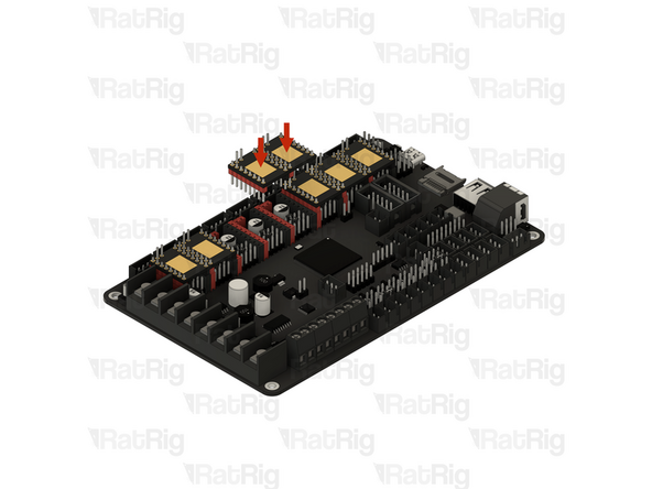
Fan voltage configuration jumpers
-
Remove all eight jumpers and set them aside
-
V-USB jumper
-
Leave this jumper installed (or install one if it is not present already)
-
-
-
It is highly recommended to flash the Octopus motherboard and ensure the board is detected in RatOS before proceeding
-
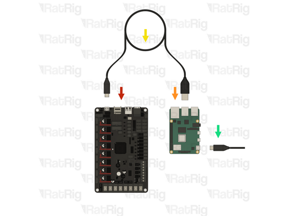
1x BIGTREETECH Octopus v1.1 motherboard
-
1x Raspberry Pi model 4B - 1GB
-
1x USB-A to USB-C cable
-
1x 5V power supply with a USB-C connector
-
The power supply is not included in the V-Core kit, but common mobile phone chargers will work as long as it can deliver at least 2.5A
-
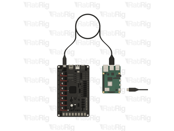
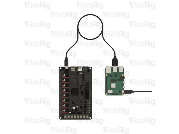
Connect the USB-C end of the cable to the Octopus motherboard and the USB-A end to any USB port on the Raspberry Pi
-
Follow the installation instructions on the RatOS website until you reach step 2 of "Setting up your printer". Then power down RatOS and the Raspberry Pi before continuing
-
-
-
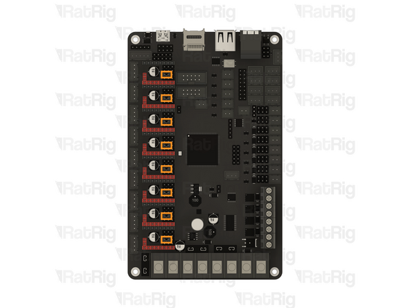
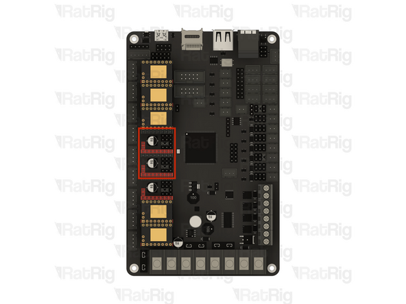
The following jumper configurations are intended for the electronics kit provided by Rat Rig. Do not blindly follow these instructions if using different hardware
-
Before proceeding, make sure the Raspberry Pi is powered down and unplugged and the USB cable between the Octopus motherboard and Raspberry Pi has been disconnected
-
V-USB jumper
-
Remove this jumper and set it aside
-
Stepper driver configuration jumpers
-
Install one jumper onto each position shown
-
This configures the stepper drivers in UART mode, allowing RatOS to tune and control them directly
-
Double-check the positions of all jumpers before continuing, failure to do so can lead to damage to the electronics
-
-
-
The following jumper configurations are intended for the electronics kit provided by Rat Rig. Do not blindly follow these instructions if using different hardware
-
Fan voltage configuration jumpers
-
24V - Electronics enclosure fan
-
12V - Toolhead part cooling fan
-
12V - Second toolhead part cooling fan (IDEX only)
-
24V - VAOC cooling fan (IDEX only)
-
Double-check the positions of all jumpers before continuing, failure to do so can lead to damage to the electronics
-
Store any remaining jumpers somewhere safe for future use
-
-
-
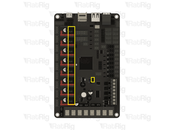
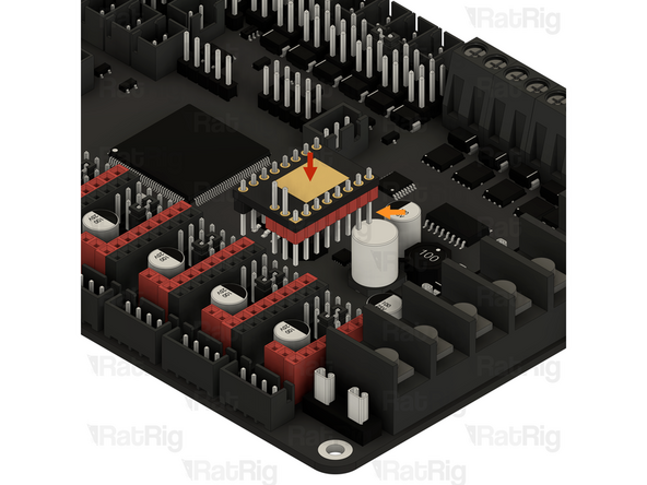
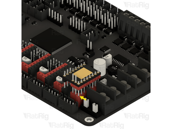
This step shows how to correctly install a stepper driver into the Octopus motherboard
-
1x BIGTREETECH TMC2209 Stepper driver
-
Align the stepper driver as shown with the longest pins facing downwards
-
Line up the pins of the stepper driver with the socket on the motherboard as shown
-
Once aligned, push the stepper driver down to fully seat it into the socket
-
-
-
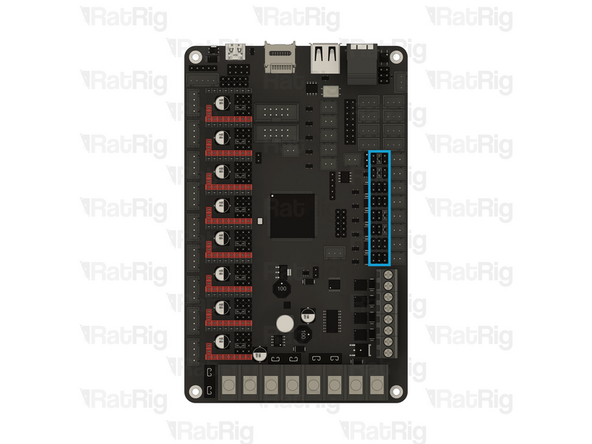
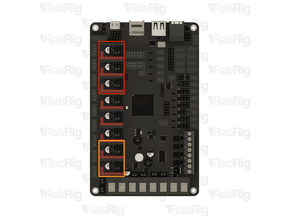
The following stepper driver configuration is intended for the electronics kit provided by Rat Rig. Do not blindly follow these instructions if using different hardware
-
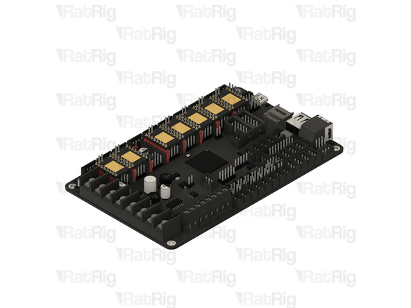
Install a stepper driver into each marked socket
-
3x BIGTREETECH TMC2209 Stepper driver
-
These stepper drivers control the Z-axis
-
2x BIGTREETECH TMC2209 Stepper driver
-
These stepper drivers control the X and Y axes
-
If you are building a CoreXY variant of the V-Core 4.0, then please skip to step 46
-
If you are building a Hybrid or IDEX variant of the V-Core 4.0, then please continue following the next steps
-
-
-
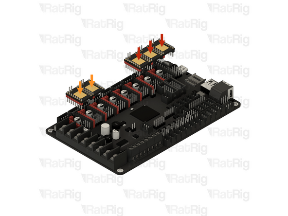
The following stepper driver configuration is intended for the electronics kit provided by Rat Rig. Do not blindly follow these instructions if using different hardware
-
Install a stepper driver into each marked socket
-
2x BIGTREETECH TMC2209 Stepper driver
-
These stepper drivers control the additional stepper motors for the Hybrid or IDEX variants of the V-Core 4.0
-
-
-
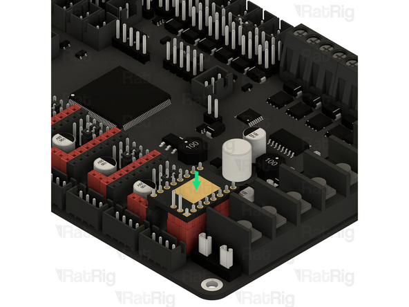
This step shows how to correctly install a stepper driver heatsink
-
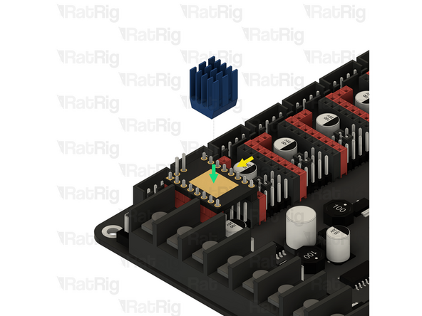
1x Blue anodised heatsink
-
Adhesive pad cover
-
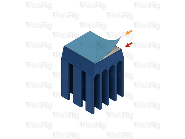
The adhesive to secure the heatsink to the stepper driver has a thin, blue, plastic cover, this needs to be peeled off
-
1x BIGTREETECH TMC2209 Stepper driver
-
Align the heatsink with the centre of the stepper driver as shown
-
The orientation of the heatsink does not matter, but they look better when all oriented the same way
-
Press the heatsink down gently for 5–10 seconds to make sure it adheres well
-
-
-
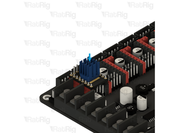
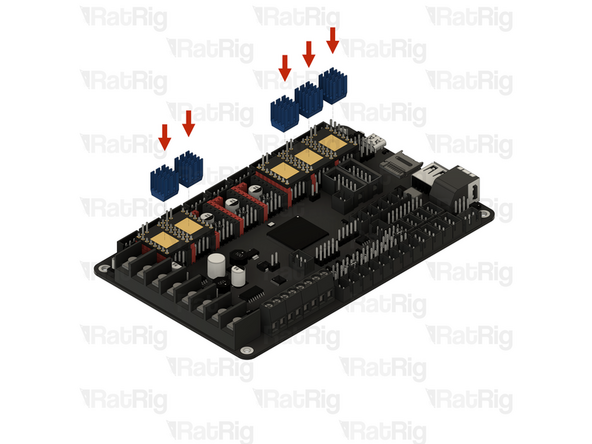
Install a heatsink onto each stepper driver
-
5x Blue anodised heatsink
-
You will need one heatsink per driver — for the Hybrid or IDEX variants of the V-Core 4.0, this means seven heatsinks instead of five
-
-
-
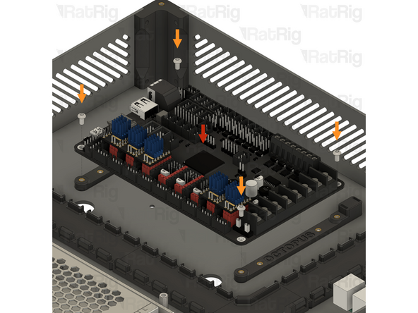
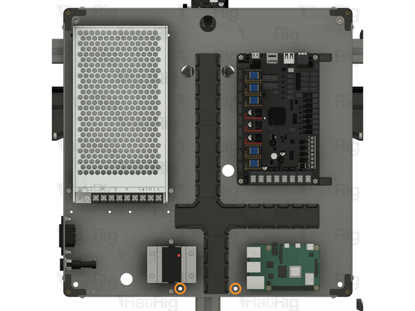
Prepared BIGTREETECH Octopus v1.1 motherboard
-
Align the Octopus motherboard with the printed mount as shown
-
4x M3x6 Button Head Screw
-
Tighten all four M3x6 Button Head Screws to secure the Octopus motherboard to the printed mount
-
Be careful not to overtighten the screws as you can damage the Octopus motherboard or the printed parts
-
-
-
If you are building a CoreXY or Hybrid variant of the V-Core 4.0, then please continue following the next steps
-
If you are building an IDEX variant of the V-Core 4.0, then please skip to step 51
-
-
-
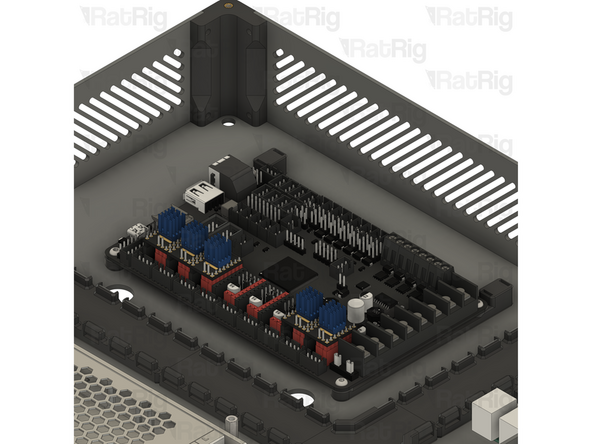
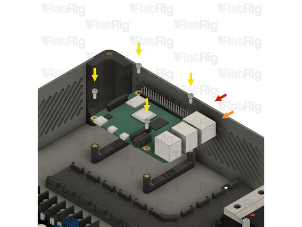
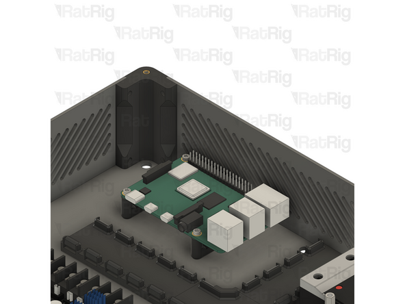
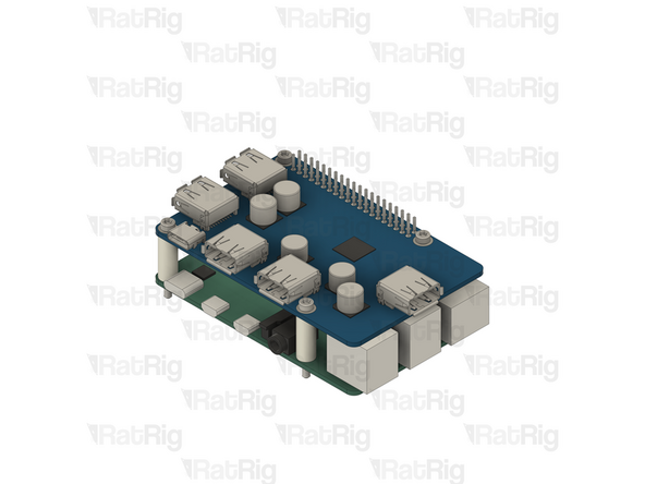
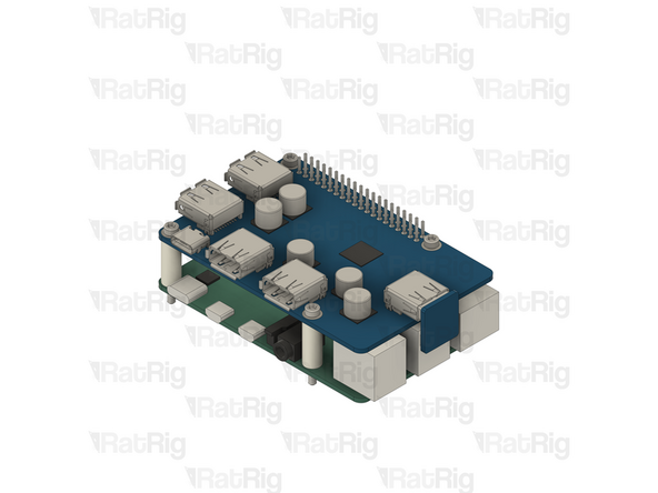
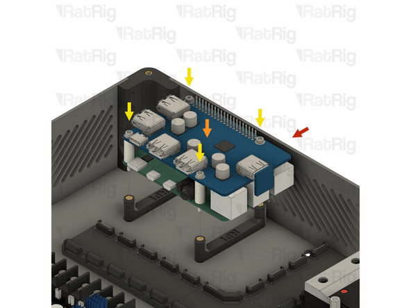
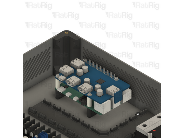
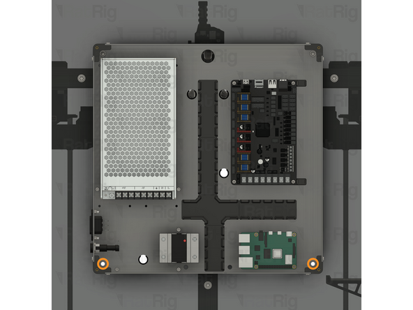
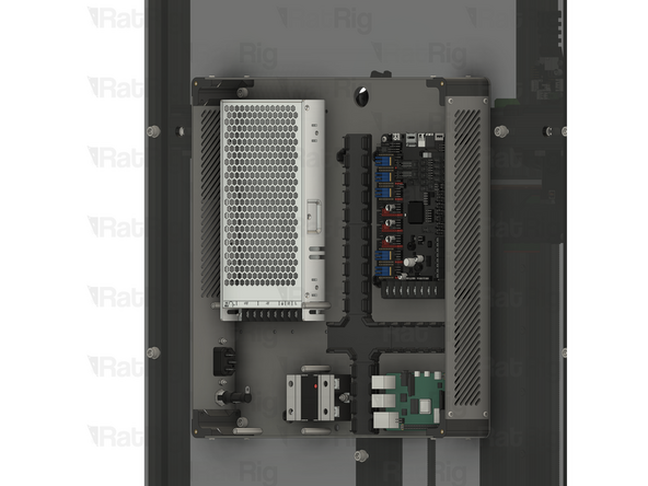
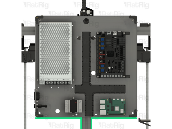
Electronics enclosure assembly
-
1x Raspberry Pi model 4B
-
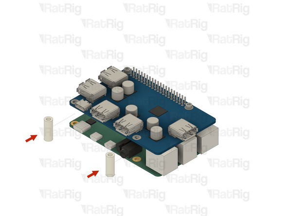
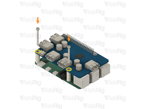
Align the Raspberry Pi with the printed mount as shown
-
4x M2.5x6 Cap Head Screw
-
Tighten all four M2.5x6 Cap Head Screws to secure the Raspberry Pi to the printed mount
-
Be careful not to overtighten the screws as you can damage the Raspberry Pi or the printed parts
-
Set the electronics enclosure assembly aside until later in the guide
-
The next few steps are specific to the IDEX variant. If you are building the CoreXY or Hybrid variant, please skip to step 57
-
-
-
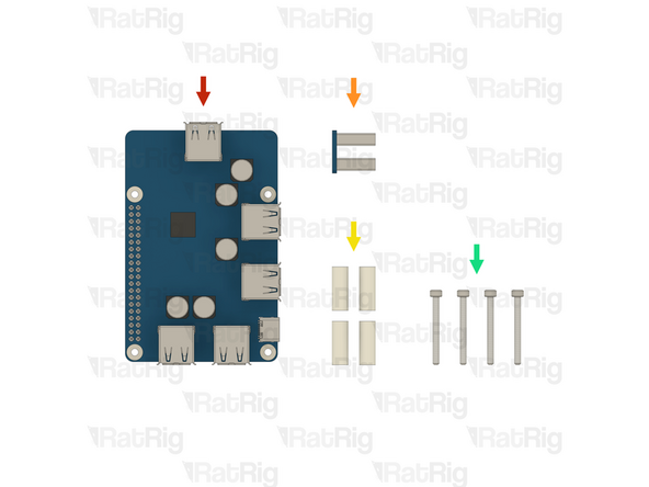
1x Waveshare USB 3.2 Raspberry Pi Hub (SKU: HW4002EC)
-
1x Waveshare USB Hub-to-Pi connector (Included in the usb hub box)
-
4x Nylon spacer - 3.2x6x16mm (SKU: HW4006NC)
-
4x M2.5x25 Cap Head Screw (SKU: HW4005SC)
-
-
-
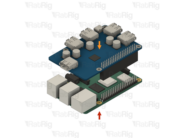
1x Raspberry Pi model 4B - 1GB
-
1x Waveshare USB 3.2 Raspberry Pi Hub
-
Align the female socket with the GPIO pins on the Raspberry Pi as shown
-
Apply gentle downwards force to install the USB hub onto the Raspberry Pi
-
-
-
2x Nylon spacer - 3.2x6x16mm
-
Insert each of the nylon spacers into the gap, aligned with the screw holes as shown
-
2x M2.5x25 Cap Head Screw
-
Insert an M2.5x25 Cap Head Screw into each of the marked screw holes, passing through the nylon spacer and out the bottom of the Raspberry Pi
-
-
-
2x Nylon spacer - 3.2x6x16mm
-
Insert each of the nylon spacers into the gap, aligned with the screw holes as shown
-
2x M2.5x25 Cap Head Screw
-
Insert an M2.5x25 Cap Head Screw into each of the marked screw holes, passing through the nylon spacer and out the bottom of the Raspberry Pi
-
-
-
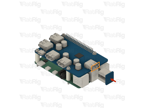
1x Waveshare USB Hub-to-Pi connector
-
Install the Hub-to-Pi connector into the marked USB port on the hub, and the USB port on the Raspberry Pi below
-
-
-
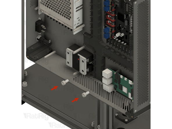
Electronics enclosure assembly from step 48
-
1x Raspberry Pi and USB hub assembly
-
Align the Raspberry Pi assembly with the printed mount as shown
-
4x M2.5x25 Cap Head Screw
-
Tighten all four M2.5x25 Cap Head Screws to secure the Raspberry Pi assembly to the printed mount
-
Be careful not to overtighten the screws as you can damage the Raspberry Pi or the printed parts
-
Set the electronics enclosure assembly aside until later in the guide
-
-
-
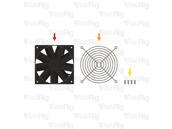
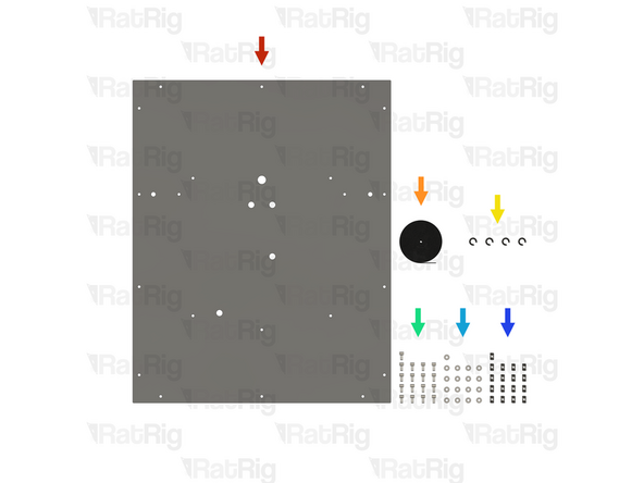
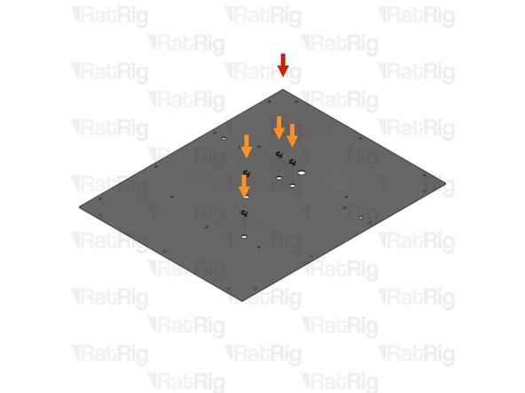
1x Fan - 120x15 Axial 24V (SKU: HW3945EC)
-
1x Fan Grille - 120mm - Black (SKU: HW3937GC)
-
4x Self-tapping Screw - Plastic fan - 12mm (SKU: HW3892SC)
-
-
-
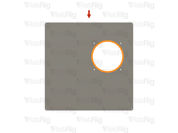
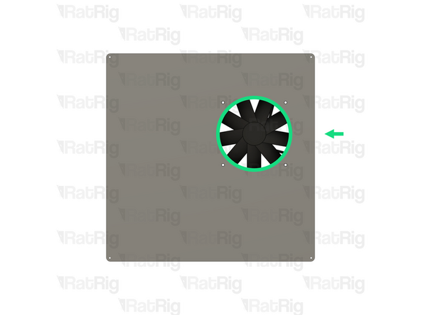
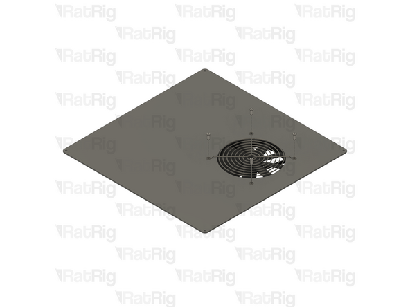
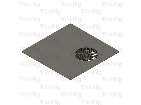
1x Lid panel from step 2
-
Make sure the panel is oriented as shown, with the large circular hole closest to the top right corner
-
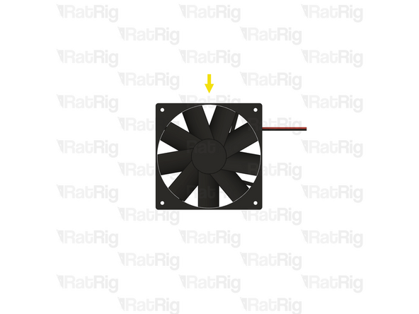
1x Fan - 120x15 Axial 24V
-
Orient the fan so that the label on the fan faces away from the lid panel and the cable exits the right-hand side
-
Slide the fan under the panel, aligning it with the hole as shown
-
-
-
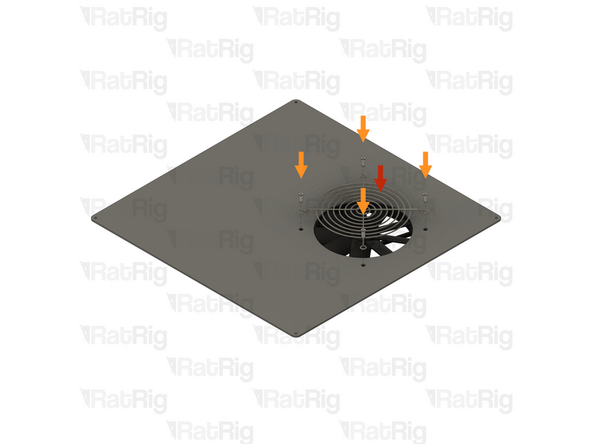
1x Fan Grille - 120mm - Black
-
Position the fan grille over the fan as shown
-
4x Self-tapping Screw - Plastic fan - 12mm
-
Tighten all four self-tapping screws to secure the fan grille and fan to the panel
-
The self-tapping screws will cut a thread into the plastic of the fan and may take some effort to fasten
-
Set the lid assembly aside for now, it will be needed after the wiring guide is complete
-
-
-
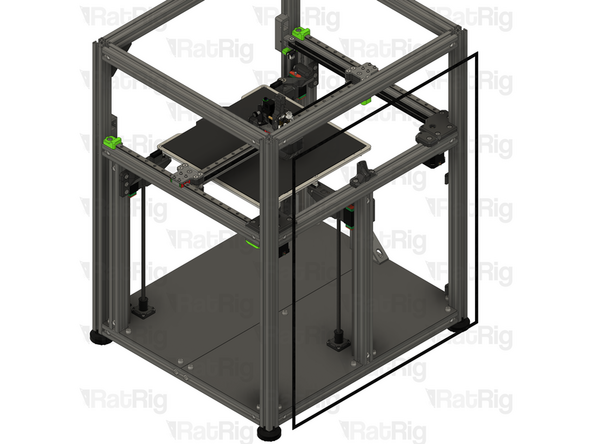
1x Rear V-Core 4.0 panel
-
Please note: The V-Core 4.0 panels are not included in the kit and must be sourced separately
-
The V-Core 4.0 is designed to use 4mm thick panels in either polycarbonate or acrylic
-
1x Foam Strip - 1mm x 8mm (SKU: HW2943GC)
-
4x vc4_grommet (SKU: PP000286)
-
17x M6x12 Cap Head Screw (SKU: HW1836SC)
-
17x M6 Washer (SKU: HW2746NC)
-
17x T-Nut Drop-in for 30 series - M6 (SKU: HW1361NC)
-
-
-
1x Rear V-Core 4.0 panel
-
Orient the panel as shown, making sure the bottom offset hole is to the right
-
4x vc4_grommet
-
Install a printed grommet into each of the marked holes
-
Flip the panel over so that the bottom offset hole is now on the left
-
-
-
17x M6x12 Cap Head Screw
-
17x M6 Washer
-
Install an M6 washer onto each of the M6x12 Cap Head Screws, and then insert the screw into each of the marked holes
-
-
-
17x T-Nut Drop-in for 30 series - M6
-
Loosely thread a 3030 T-nut onto each of the M6x12 screws. Do not tighten them at this point
-
Set the assembled panel aside until step 66
-
-
-
V-Core 4.0 Assembly - Rear side
-
Cut the following lengths of the 8mm x 1mm foam strip depending on the V-Core 4.0 size:
-
V-Coro 4.0 300: 2x 560mm, 2x 694mm
-
V-Coro 4.0 400: 2x 660mm, 2x 794mm
-
V-Coro 4.0 500: 2x 760mm, 2x 894mm
-
Peel the protective backing from the back of the foam strip and apply the shorter lengths to the top and bottom extrusions as shown
-
Peel the protective backing from the back of the foam strip and apply the longer lengths to the side extrusions as shown
-
-
-
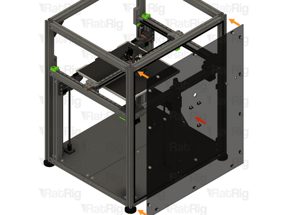
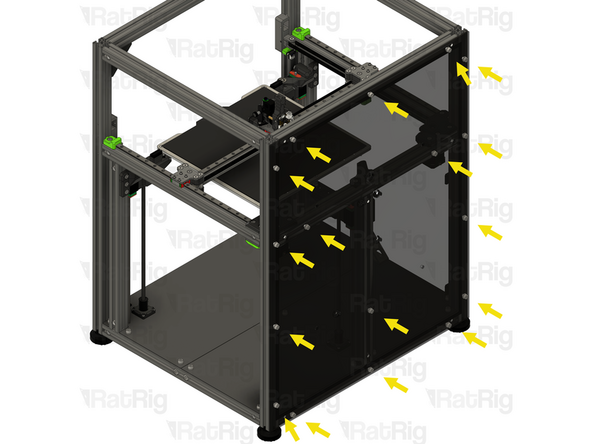
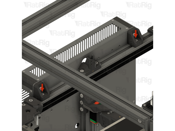
1x V-Core 4.0 rear panel assembly from step 64
-
Align the rear panel with the frame, making sure all T-nuts slot into the extrusion slots
-
Secure the panel to the frame by tightening all seventeen M6x12 screws
-
Do not overtighten the screws as you can damage the panel
-
-
-
4x M6x12 Cap Head Screw (SKU: HW1836SC)
-
4x M6 Locking Hex Nut (SKU: HW1311NC)
-
-
-
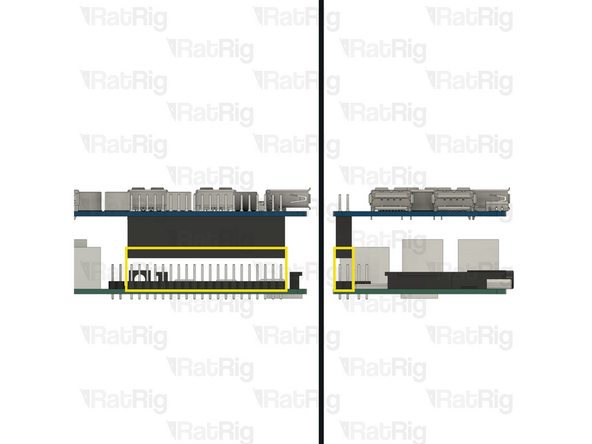
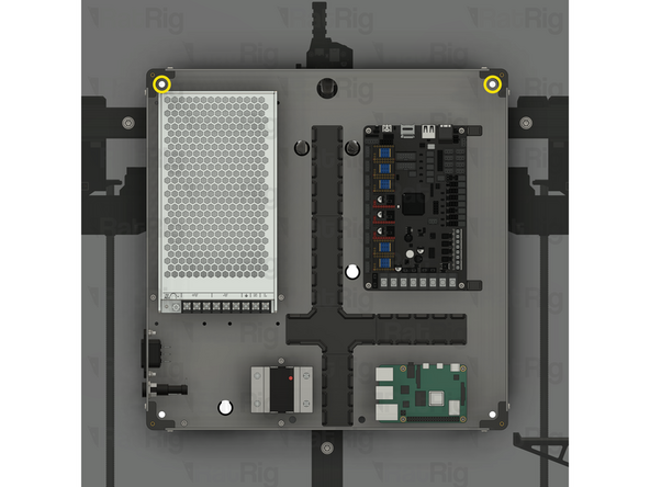
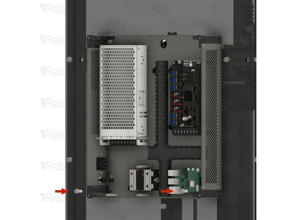
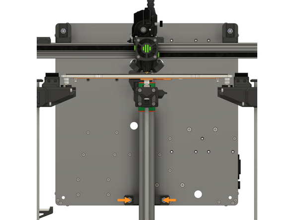
Electronics enclosure assembly from step 50 (or step 56 for IDEX)
-
2x M6x12 Cap Head Screw
-
Insert an M6x12 Cap Head Screw into each of the marked holes within the electronics enclosure
-
Align the M6x12 screws with the holes in the rear panel and push them through
-
Continue to support the electronics enclosure until the locking hex nuts are installed in the next step
-
-
-
2x M6 Locking Hex Nut
-
Install an M6 Locking Hex Nut onto each of the M6x12 screws and tighten them to secure the electronics enclosure to the panel
-
The M6 Locking Hex Nuts can be held with a 10mm spanner, wrench or socket
-
Do not overtighten the screws as you can damage the panel
-
-
-
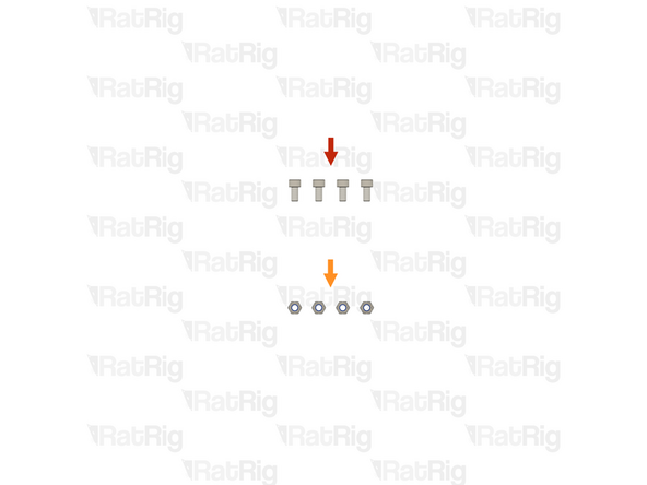
2x M6x12 Cap Head Screw
-
Insert an M6x12 Cap Head Screw into each of the marked holes within the electronics enclosure, and through the panel
-
-
-
2x M6 Locking Hex Nut
-
Install an M6 Locking Hex Nut onto each of the M6x12 screws and tighten them to secure the electronics enclosure to the panel
-
The M6 Locking Hex Nuts can be held with a 10mm spanner, wrench or socket
-
Do not overtighten the screws as you can damage the panel
-
-
-
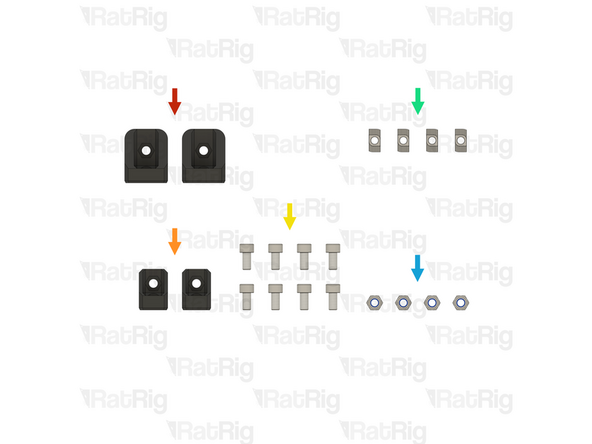
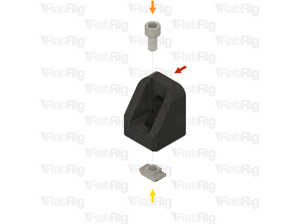
2x vc4_electronics_mount_upper (SKU: PP000320)
-
2x vc4_electronics_mount_lower (SKU: PP000319)
-
8x M6x12 Cap Head Screw (SKU: HW1836SC)
-
4x T-Nut Drop-in for 30 series - M6 (SKU: HW1361NC)
-
4x M6 Locking Hex Nut (SKU: HW1311NC)
-
-
-
1x vc4_electronics_mount_upper
-
1x M6x12 Cap Head Screw
-
1x T-Nut Drop-in for 30 series - M6
-
Loosely thread a 3030 T-nut onto the M6x12 screw. Do not tighten it at this point
-
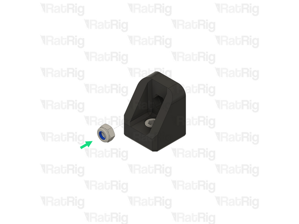
1x M6 Locking Hex Nut
-
Insert the M6 Locking Hex Nut into the printed part as shown
-
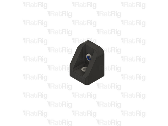
Prepare two of these assemblies and set them aside until step 76
-
-
-
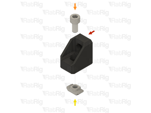
1x vc4_electronics_mount_lower
-
1x M6x12 Cap Head Screw
-
1x T-Nut Drop-in for 30 series - M6
-
Loosely thread a 3030 T-nut onto the M6x12 screw. Do not tighten it at this point
-
1x M6 Locking Hex Nut
-
Insert the M6 Locking Hex Nut into the printed part as shown
-
Prepare two of these assemblies and set them aside until step 78
-
-
-
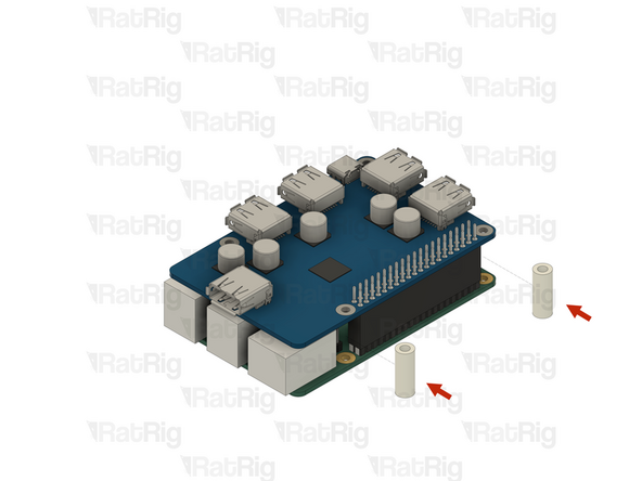
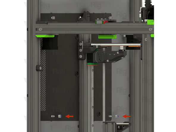
Electronics enclosure assembly from step 50 (or step 56 for IDEX)
-
2x M6x12 Cap Head Screw
-
Insert an M6x12 Cap Head Screw into each of the marked holes within the electronics enclosure
-
2x Upper electronics enclosure mount assemblies from step 74
-
Fasten an upper mount assembly on to each M6x12 cap head screw. Do not fully tighten the screws yet, they will be tightened in an upcoming step
-
-
-
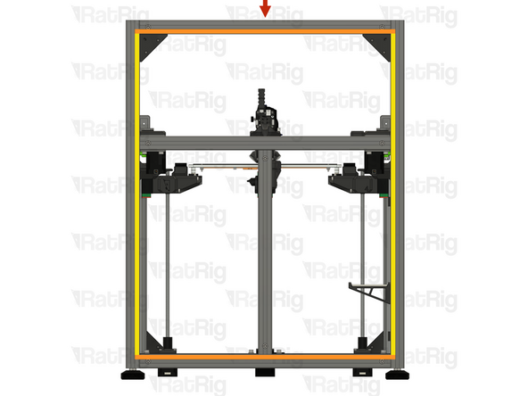
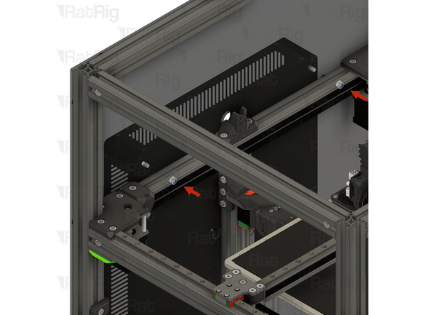
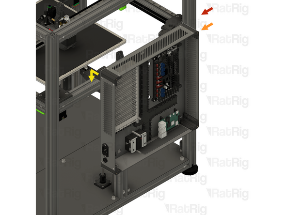
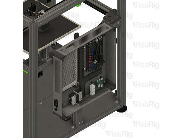
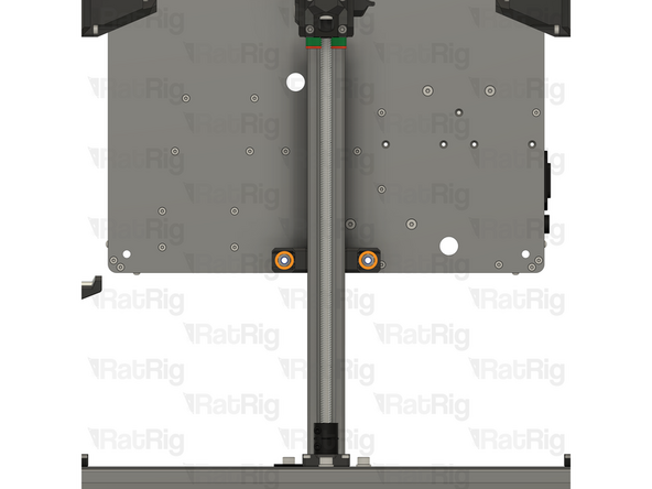
V-Core 4.0 Assembly - Rear side
-
Electronics enclosure assembly
-
Install the electronics enclosure by positioning the upper mounts onto the 3030 extrusion as shown
-
Make sure the T-nuts on the upper mounts fit inside the extrusion slot
-
The electronics enclosure should now support itself, even though the screws have not yet been tightened
-
Position the electronics enclosure so it is roughly centered with the marked 3030 extrusion. The exact position will be set in the next step
-
-
-
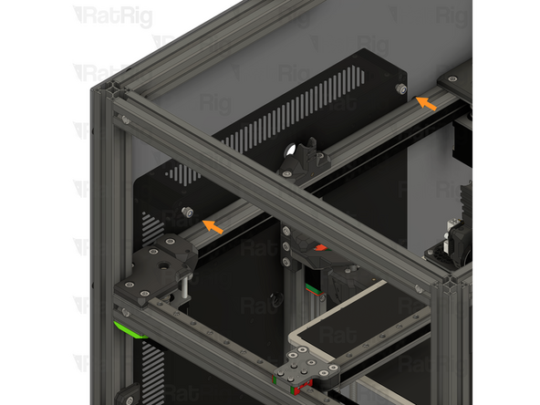
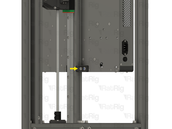
2x Lower electronics enclosure mount assemblies from step 75
-
Align each lower mount assembly so that the T-nut fits into the extrusion slot and the locking hex nut aligns with the hole in the electronics enclosure
-
Tighten the M6x12 Cap Head Screw to secure the mount to the extrusion
-
Be careful not to overtighten the screws as you can damage the printed parts
-
-
-
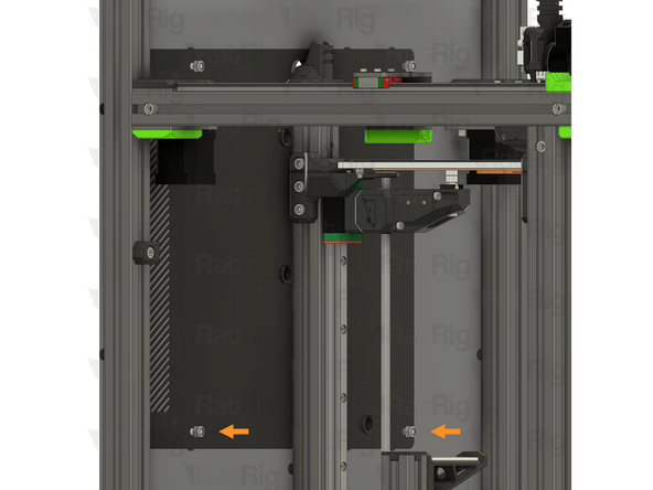
2x M6x12 Cap Head Screw
-
Insert an M6x12 Cap Head Screw into each of the marked holes within the electronics enclosure
-
Thread the M6x12 Cap Head Screws into the locking nuts in the lower electronics enclosure mounts
-
Fully tighten both M6x12 Cap Head Screws to secure the electronics enclosure to the frame
-
-
-
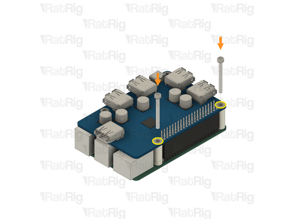
Fully tighten both marked M6x12 Cap Head Screws to secure the upper mounts to the frame
-
Fully tighten both marked M6x12 Cap Head Screws to secure the lower mounts to the frame
-
Fully tighten all four marked M6x12 Cap Head Screws to secure the electronics enclosure to the upper and lower mounts
-
Be careful not to overtighten the screws as you can damage the printed parts
-


Cancel: I did not complete this guide.
5 other people completed this guide.
One Comment
I Like to use an Alu Bond Plate as Backplate instaed of PTEG any thoughts on this one? IS that possible ?
ds3975@gmail.com - Open Reply