
-
-
24x M6 Nylon Locking Hex Nut
-
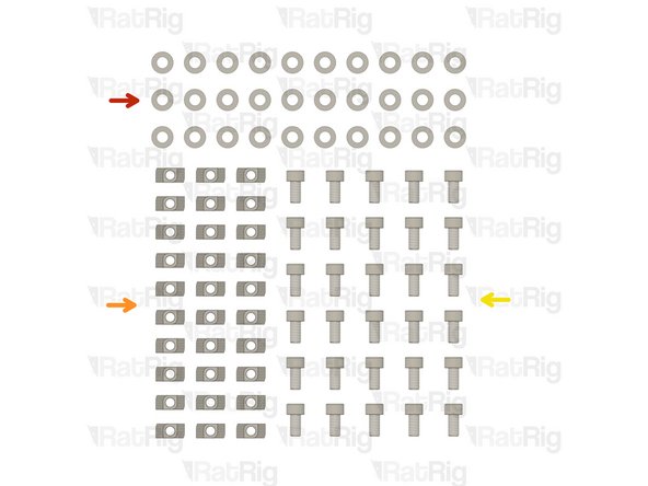
16x M6 Washer
-
16x M6x12 Cap Head Screw
-
2x vc4_magnet_handle
-
8x M6x16 Cap Head Screw
-
8x vc4_magnet_panel
-
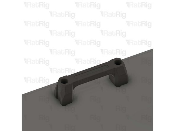
4x vc4_printed_handle
-
20x Magnet - Neodymium disc 10x4mm
-
-
-
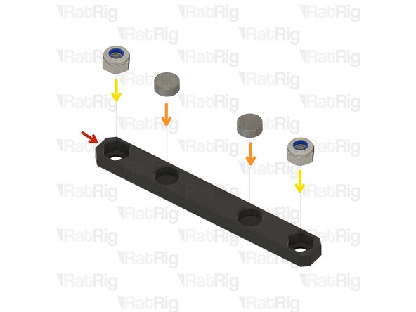
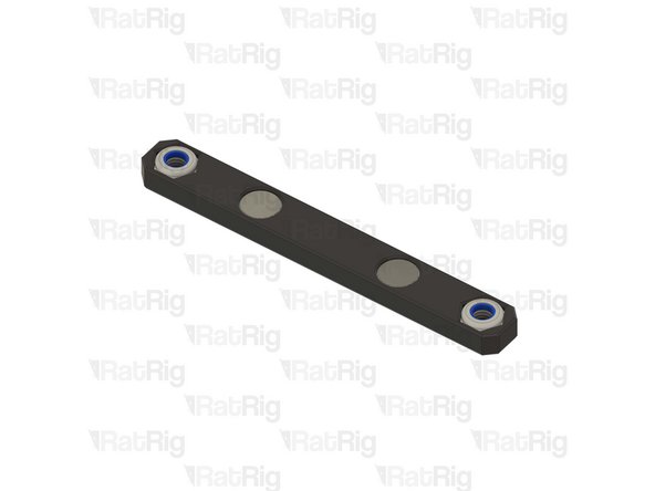
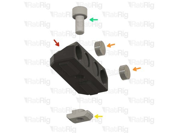
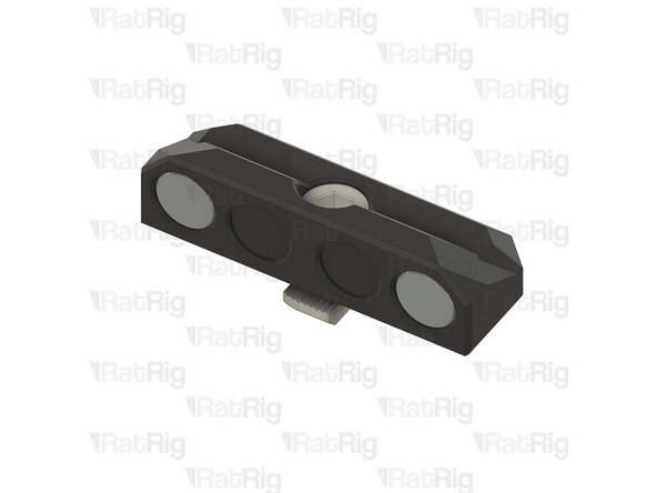
vc4_magnet_handle
-
Magnet - Neodymium disc 10x4mm
-
M6 Nylon Locking Hex Nut
-
Prepare two assemblies
-
Tip: Use a drop of super glue to prevent the magnets from coming off over time.
-
-
-
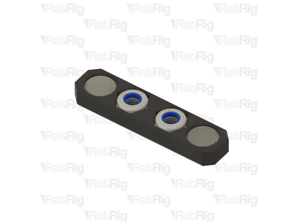
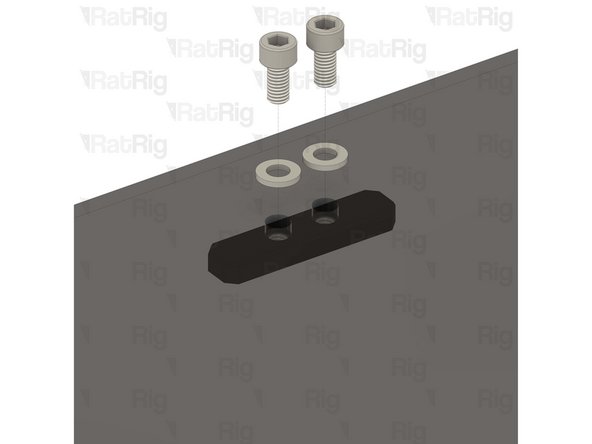
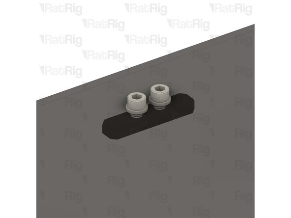
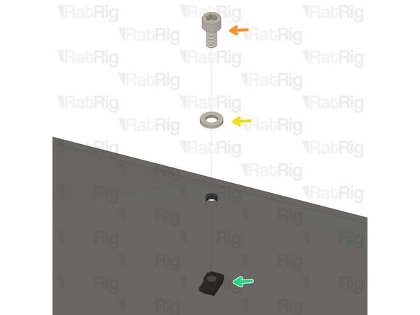
vc4_magnet_panel
-
Magnet - Neodymium disc 10x4mm
-
M6 Nylon Locking Hex Nut
-
Prepare eight assemblies
-
Tip: Use a drop of super glue to prevent the magnets from coming off over time.
-
-
-
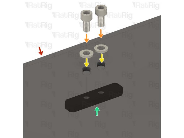
vc4_panel_door
-
M6x12 Cap Head Screw
-
M6 Washer
-
Door magnet panel assembly from Step 4
-
Repeat this step all around the panel
-
Take care not to over tighten the M6x12 screw as you can damage the printed parts
-
-
-
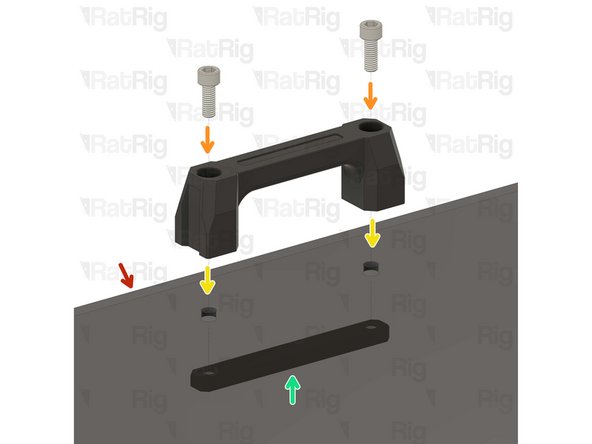
vc4_panel_door assembly
-
M6x16 Cap Head Screw
-
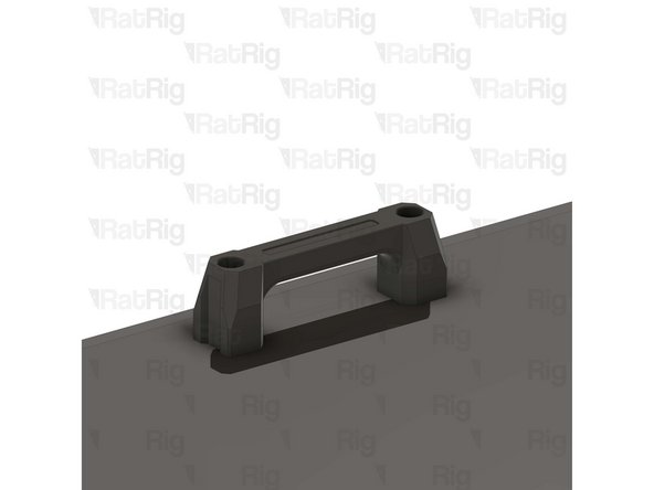
vc4_printed_handle
-
door magnet handle assembly from Step 3
-
Do not overly tighten the M6 nylon locking hex nuts when securing the handles, as this can cause the panel to warp which will prevent a good seal to the printer
-
-
-
Completed door panel assembly
-
Set the completed door assembly aside until Step 23
-
-
-
vc4_panel_top
-
M6x12 Cap Head Screw
-
M6 Washer
-
Door magnet panel assembly from Step 4
-
Repeat this step all around the panel
-
Take care not to over tighten the M6x12 screw as you can damage the printed parts
-
-
-
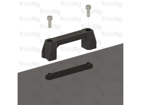
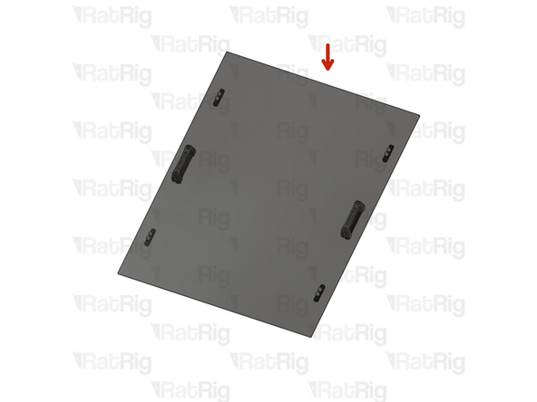
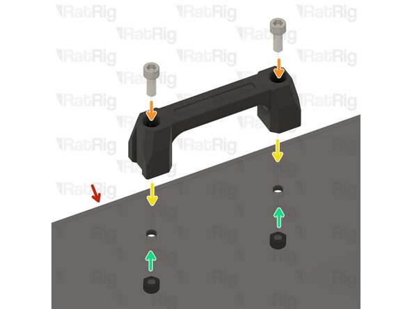
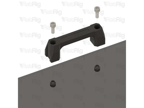
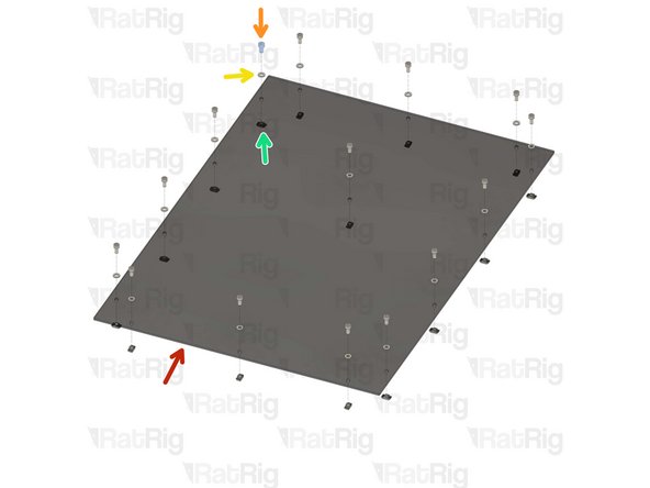
vc4_panel_top
-
M6x16 Cap Head Screw
-
vc4_printed_handle
-
M6 Nylon Locking Hex Nut
-
Do not overly tighten the M6 nylon locking hex nuts when securing the handles, as this can cause the panel to warp which will prevent a good seal to the printer
-
-
-
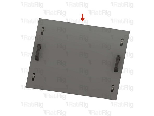
Completed top panel assembly
-
Set the completed top assembly aside until Step 21
-
-
-
30x M6 Washer
-
30x 3030 Drop-in T-Nut - M6
-
30x M6x12 Cap Head Screw
-
-
-
vc4_panel_side
-
M6x12 Cap Head Screw
-
M6 Washer
-
3030 Drop-in T-Nut - M6
-
Loosely thread the 3030 T-Nuts onto the M6x12 screws. Do not tighten them at this point.
-
-
-
1x Adhesive backed foam sealing tape
-
10x vc4_magnet_frame
-
2x vc4_door_support
-
12x M6x12 Cap Head Screw
-
12x 3030 Drop-in T-Nut - M6
-
20x Magnet - Neodymium disc 10x4mm
-
-
-
M6x12 Cap Head Screw
-
vc4_door_support
-
3030 Drop-in T-Nut - M6
-
Loosely thread the 3030 T-Nuts onto the M6x12 screws. Do not tighten them at this point.
-
Prepare two assemblies
-
-
-
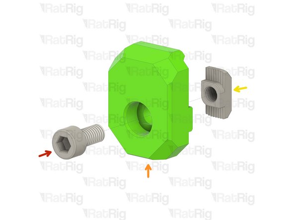
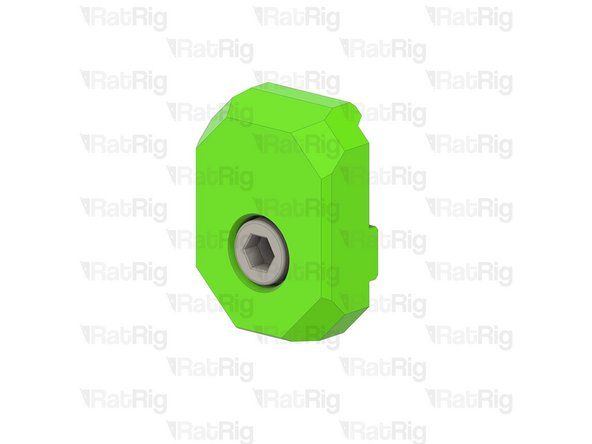
vc4_magnet_frame
-
Magnet - Neodymium disc 10x4mm
-
3030 Drop-in T-Nut - M6
-
M6x12 Cap Head Screw
-
Loosely thread the 3030 T-Nuts onto the M6x12 screws. Do not tighten them at this point.
-
Please verify the magnet polarity in relation to the magnets on the door panel. If the polarity is inverted, the magnets will repel each other instead of attracting.
-
Prepare ten assemblies
-
-
-
Adhesive foam tape
-
Cut sections of foam tape to fit in the sections shown
-
The foam seal tape is provided with an adhesive backing, peel the backing off and apply it to the frame as shown
-
-
-
Adhesive foam tape
-
Cut sections of foam tape to fit in the sections shown
-
The foam seal tape is provided with an adhesive backing, peel the backing off and apply it to the frame as shown
-
-
-
Adhesive foam tape
-
Cut sections of foam tape to fit in the sections shown
-
The foam seal tape is provided with an adhesive backing, peel the backing off and apply it to the frame as shown
-
-
-
Adhesive foam tape
-
Cut sections of foam tape to fit in the sections shown
-
The foam seal tape is provided with an adhesive backing, peel the backing off and apply it to the frame as shown
-
-
-
Horizontal 3030 panel holder assembly from Step 14
-
Tighten the M6x12 screws to secure the assemblies to the frame
-
Take care not to over tighten the M6x12 screws as you can damage the printed parts
-
-
-
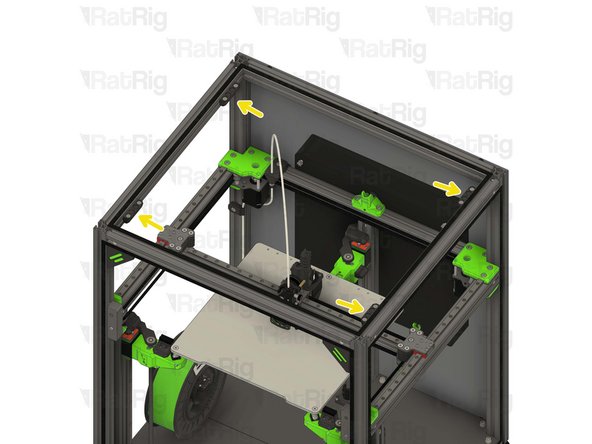
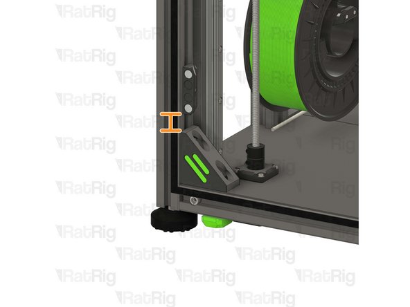
Frame magnet mount assemblies from Step 15
-
Position each magnet mount assembly as shown
-
The marked gap should measure 31.50mm
-
Tighten the M6x12 screw to secure each assembly to the frame
-
Take care not to over tighten the M6x12 screws as you can damage the printed parts
-
The exact position of the magnet mounts can be adjusted once the top panel in in place
-
-
-
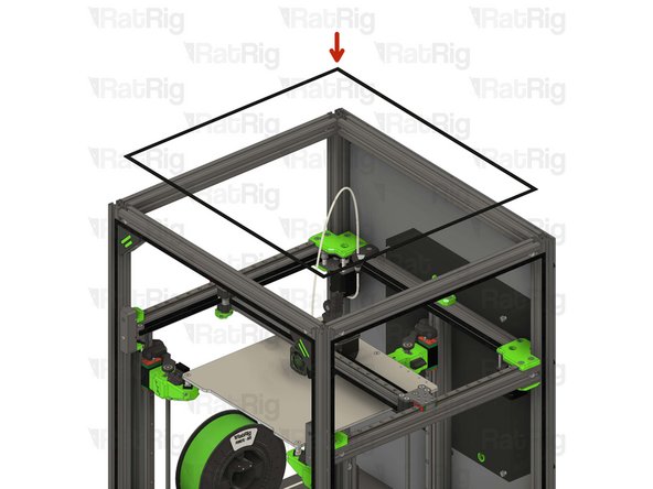
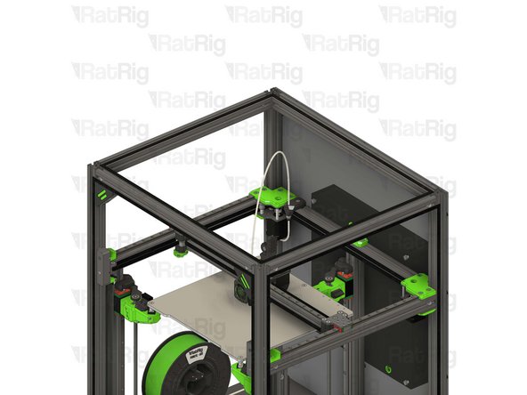
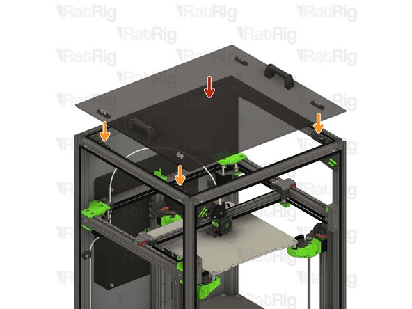
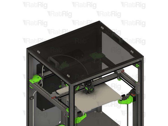
Top panel assembly from Step 10
-
Place the top panel onto the top of the printer
-
The magnets should align the panel automatically. If the alignment needs to be adjusted, alter the position of the magnet holders installed in Step 21
-
-
-
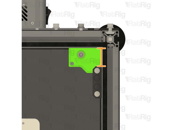
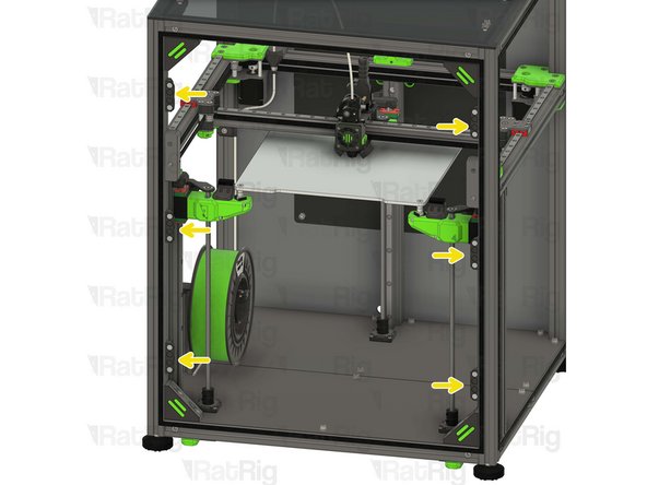
Frame magnet mount assemblies from Step 15
-
Position each magnet mount assembly as shown
-
The marked gap should measure 19.50mm
-
Tighten the M6x12 screw to secure each assembly to the frame
-
Take care not to over tighten the M6x12 screws as you can damage the printed parts
-
The exact position of the magnet mounts can be adjusted once the front panel in in place
-
-
-
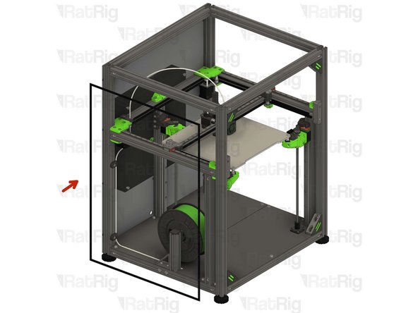
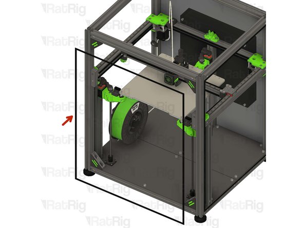
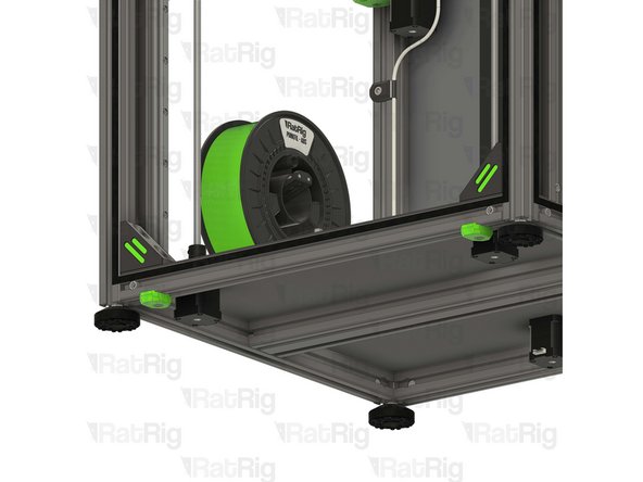
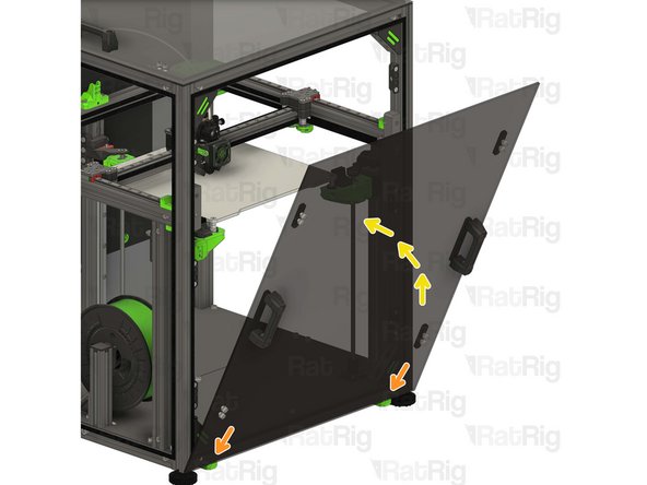
Door panel assembly from Step 7
-
Rest the door panel on the horizontal 3030 panel mounts
-
Rotate towards the printer to secure it
-
The magnets should align the panel automatically. If the alignment needs to be adjusted, alter the position of the magnet holders installed in Step 23
-
-
-
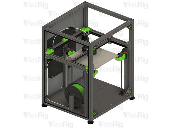
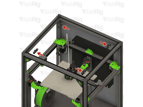
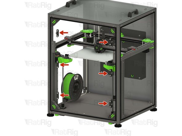
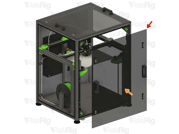
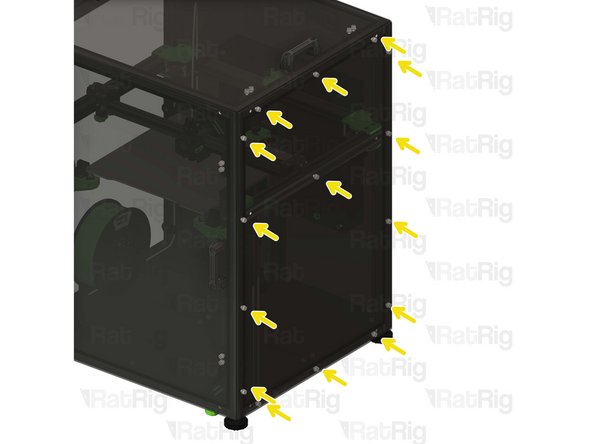
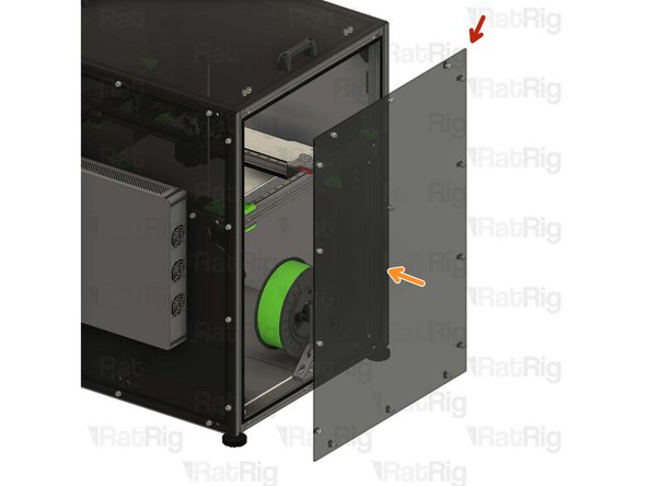
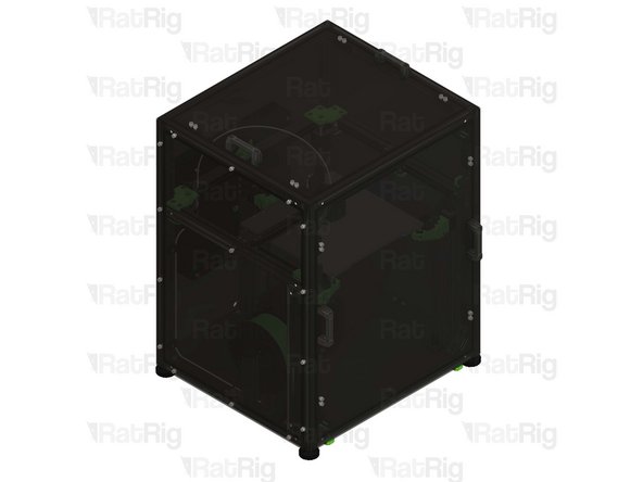
Right enclosure panel from Step 12
-
Align the panel to the frame as shown
-
Secure the panel in place by fastening the nineteen M6x12 screws
-
-
-
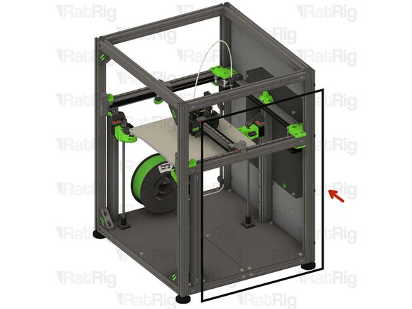
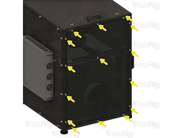
Right enclosure panel from Step 12
-
Align the panel to the frame as shown
-
Secure the panel in place by fastening the nineteen M6x12 screws
-


Cancel: I did not complete this guide.
10 other people completed this guide.
