Introduction
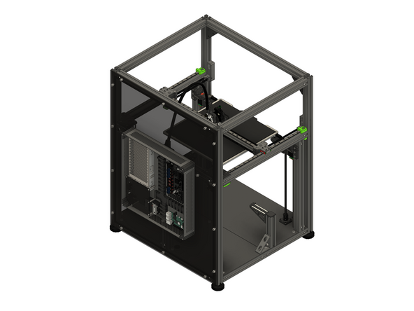
This section of the guide will step you correctly wiring all of the components used in the V-Core 4.0.
-
-
The following tools are required for this guide:
-
Allen key / hex wrenches in the following sizes: 2mm
-
Cross slot / Phillips and Flat Head screwdrivers
-
The following tools are recommended for this guide:
-
Masking / painters tape
-
-
-
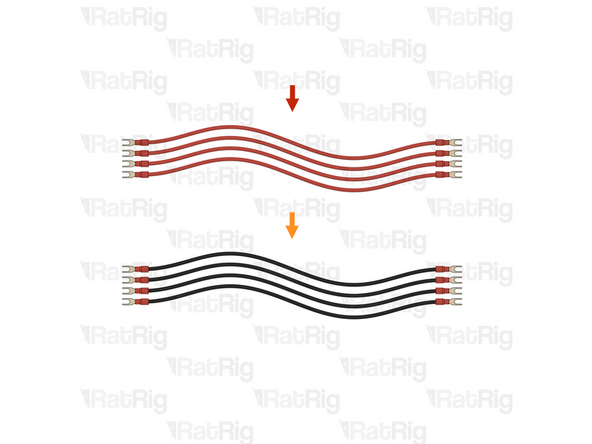
4x Prepared 24V DC Positive wire from the Preparations guide
-
4x Prepared 24V DC Negative wire from the Preparations guide
-
-
-
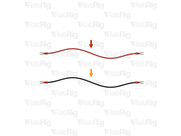
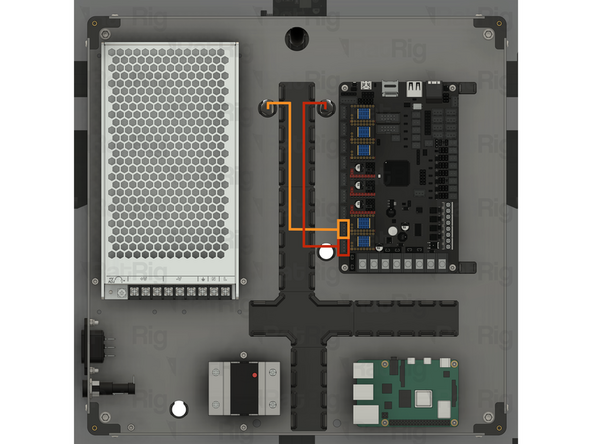
1x Prepared 24V DC Positive wire
-
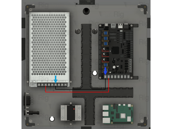
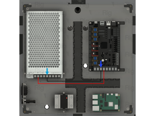
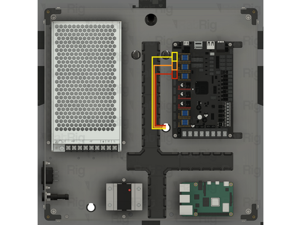
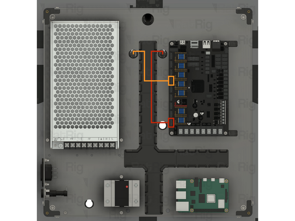
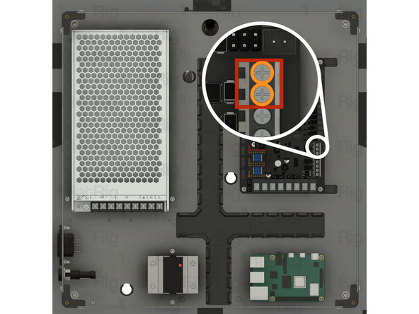
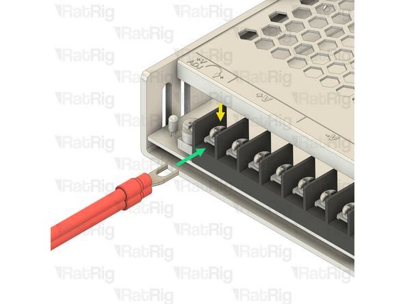
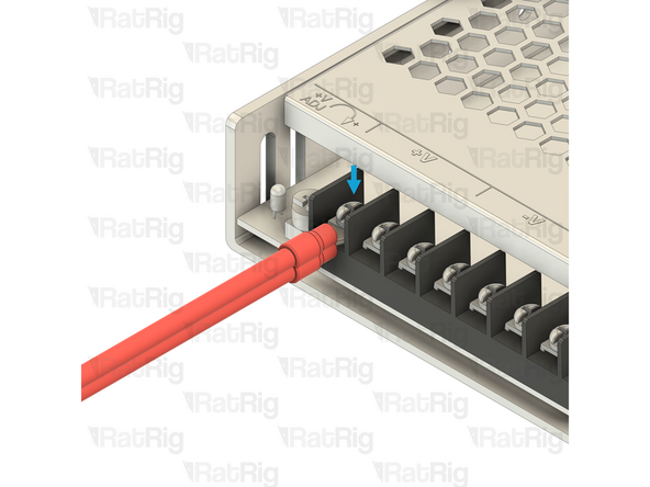
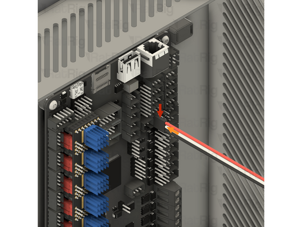
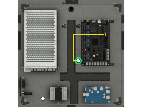
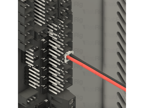
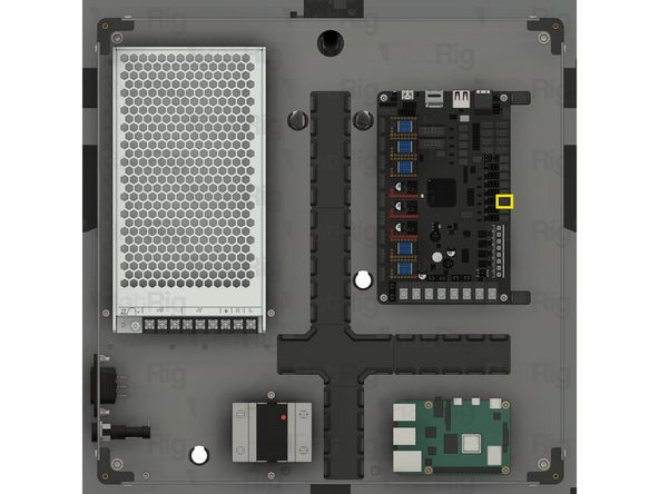
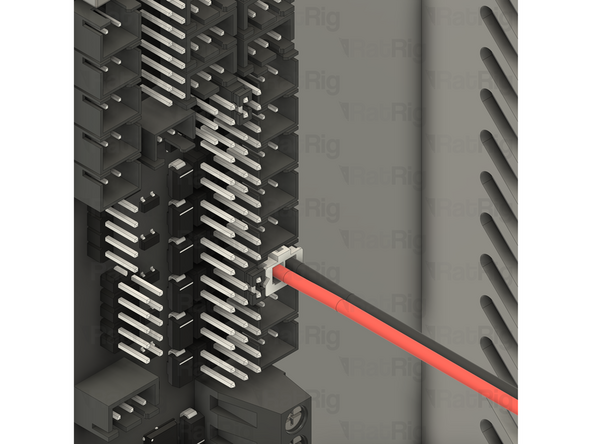
Insert the fork terminal on one end of the wire into the rightmost of the three terminals marked by the [ +V ] symbol on the power supply. Secure the fork terminal by tightening the screw
-
Insert the fork terminal on the other end of the wire into the second terminal from the left on the Octopus motherboard. Secure the fork terminal by tightening the screw
-
1x Prepared 24V DC Negative wire
-
Insert the fork terminal on one end of the wire into the rightmost of the three terminals marked by the [ -V ] symbol on the power supply. Secure the fork terminal by tightening the screw
-
Insert the fork terminal on the other end of the wire into the first terminal from the left on the Octopus motherboard. Secure the fork terminal by tightening the screw
-
After tightening the screws at each end, gently pull the wire to make sure it is firmly connected. If the fork terminal is loose, or comes out of the terminal, reinsert it and tighten the screw again
-
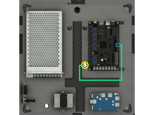
Route both wires as shown
-
-
-
1x Prepared 24V DC Positive wire
-
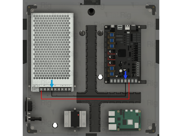
Insert the fork terminal on one end of the wire into the middle of the three terminals marked by the [ +V ] symbol on the power supply. Secure the fork terminal by tightening the screw
-
Insert the fork terminal on the other end of the wire into the forth terminal from the left on the Octopus motherboard. Secure the fork terminal by tightening the screw
-
1x Prepared 24V DC Negative wire
-
Insert the fork terminal on one end of the wire into the middle of the three terminals marked by the [ -V ] symbol on the power supply. Secure the fork terminal by tightening the screw
-
Insert the fork terminal on the other end of the wire into the third terminal from the left on the Octopus motherboard. Secure the fork terminal by tightening the screw
-
After tightening the screws at each end, gently pull the wire to make sure it is firmly connected. If the fork terminal is loose, or comes out of the terminal, reinsert it and tighten the screw again
-
Route both wires as shown
-
-
-
1x Prepared 24V DC Positive wire
-
Insert the fork terminal on one end of the wire into the leftmost of the three terminals marked by the [ +V ] symbol on the power supply. Secure the fork terminal by tightening the screw
-
Insert the fork terminal on the other end of the wire into the sixth terminal from the left on the Octopus motherboard. Secure the fork terminal by tightening the screw
-
1x Prepared 24V DC Negative wire
-
Insert the fork terminal on one end of the wire into the leftmost of the three terminals marked by the [ -V ] symbol on the power supply. Secure the fork terminal by tightening the screw
-
Insert the fork terminal on the other end of the wire into the fifth terminal from the left on the Octopus motherboard. Secure the fork terminal by tightening the screw
-
After tightening the screws at each end, gently pull the wire to make sure it is firmly connected. If the fork terminal is loose, or comes out of the terminal, reinsert it and tighten the screw again
-
Route both wires as shown
-
-
-
1x Prepared 24V DC Positive wire
-
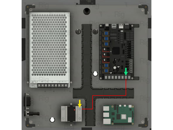
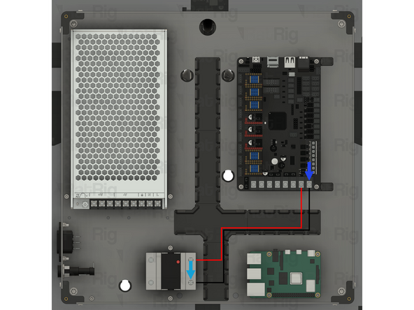
Insert the fork terminal on one end of the wire into the top terminal on the Solid State Relay. Secure the fork terminal by tightening the screw
-
Insert the fork terminal on the other end of the wire into the seventh terminal from the left on the Octopus motherboard. Secure the fork terminal by tightening the screw
-
1x Prepared 24V DC Negative wire
-
Insert the fork terminal on one end of the wire into the bottom terminal on the Solid State Relay. Secure the fork terminal by tightening the screw
-
Insert the fork terminal on the other end of the wire into the eighth terminal from the left on the Octopus motherboard. Secure the fork terminal by tightening the screw
-
It is crucial to verify that the Solid State Relay is wired correctly. Incorrect wiring will result in severe damage of the Solid State Relay. Double and triple check all of the connections before proceeding.
-
After tightening the screws at each end, gently pull the wire to make sure it is firmly connected. If the fork terminal is loose, or comes out of the terminal, reinsert it and tighten the screw again
-
-
-
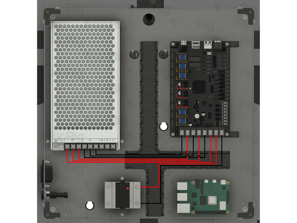
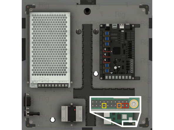
Before proceeding any further, double check that all of the 24V DC wiring matches the provided image
-
Incorrect wiring will cause irreparable damage to components
-
-
-
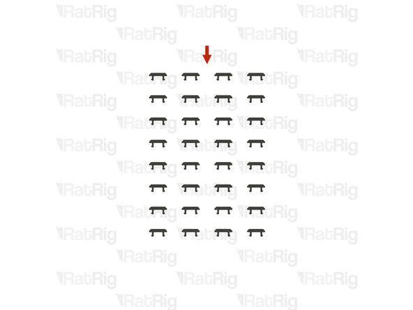
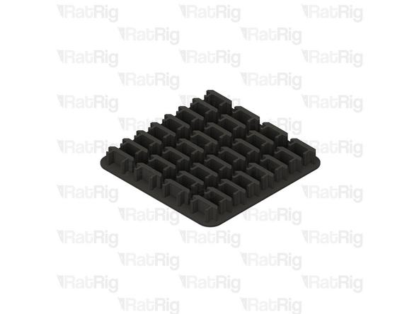
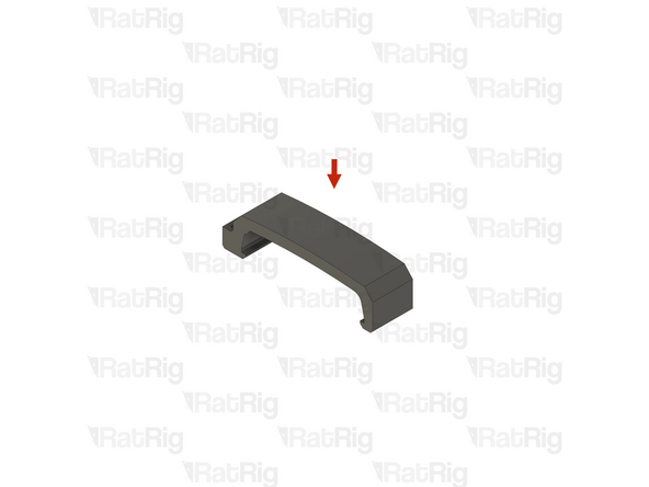
32x vc4_wire_clip (SKU: PP000337)
-
Due to their small size, the vc4_wire_clips are provided on a printed raft and must be carefully separated before use
-
-
-
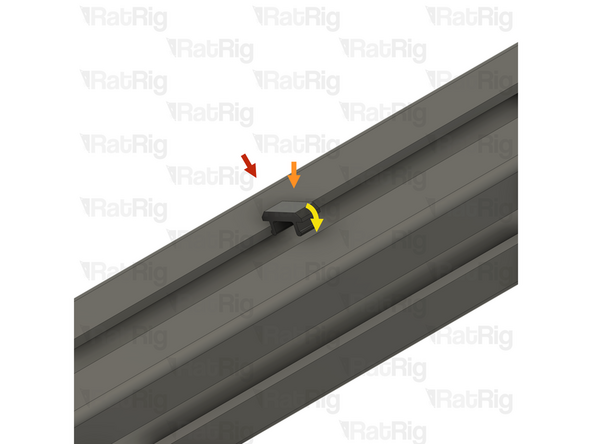
1x Example 3030 extrusion
-
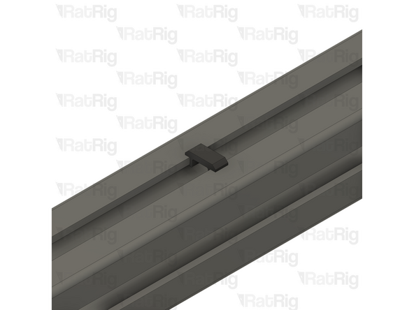
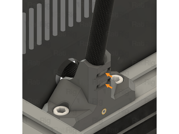
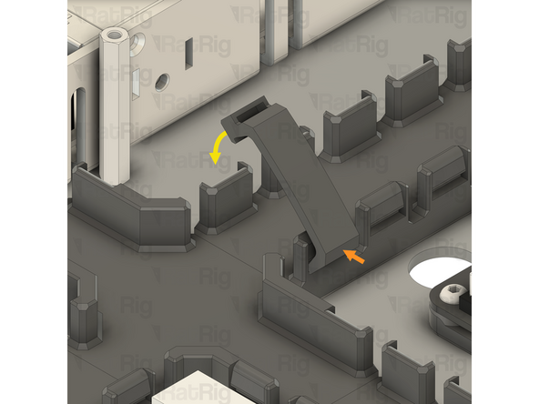
1x vc4_wire_clip
-
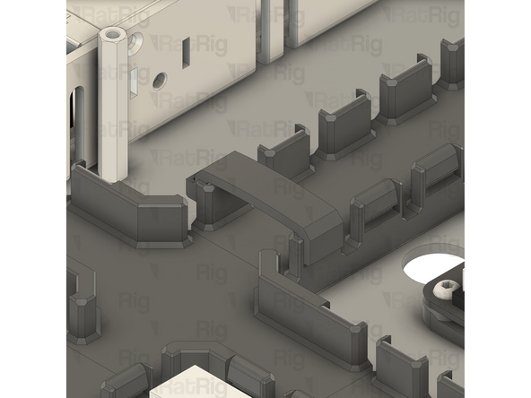
To install a wire clip into the extrusion slot, insert one end and then rotate the clip until it clicks into place
-
These clips are used to retain wires within the extrusion slot for cable management
-
In some cases, such as working on the underside of an extrusion, it can be helpful to use masking / painters tape to temporarily hold the wires inside the extrusion slot whilst installing the clips
-
-
-
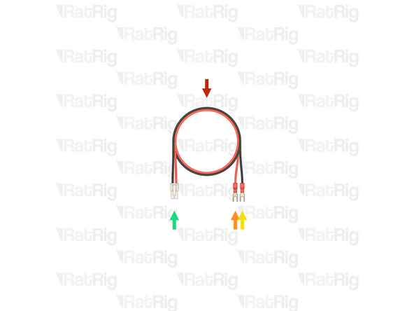
1x Cable 2000mm - 3 Conductor 24AWG - JST-XH to JST-XH (Endstop pin out) (SKU: HW3030EC)
-
-
-
1x Y-axis endstop assembly
-
1x Cable 2000mm - 3 Conductor 24AWG - JST-XH to JST-XH (Endstop pin out)
-
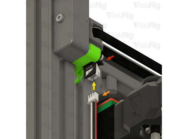
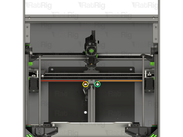
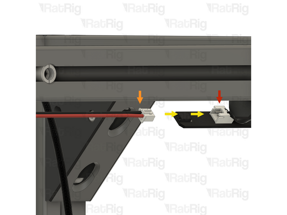
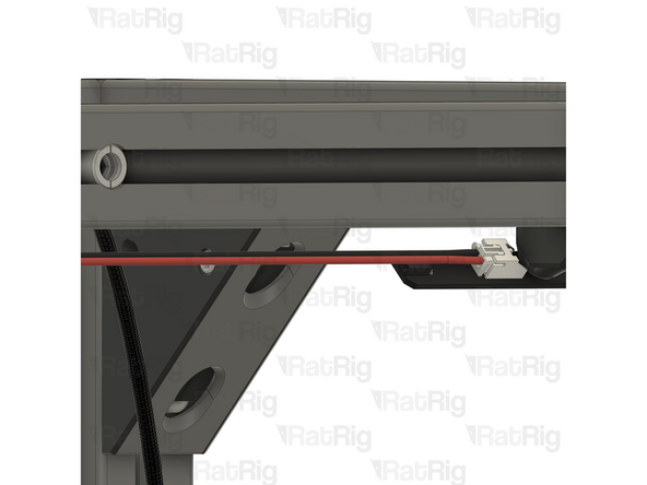
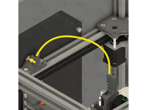
Connect one end of the endstop cable to the Y-axis endstop as shown
-
Make sure that you are using the correct cable and connect the correct end to the endstop. The wire colours and order should match the image. Incorrect wiring can damage the endstop module and Octopus motherboard
-
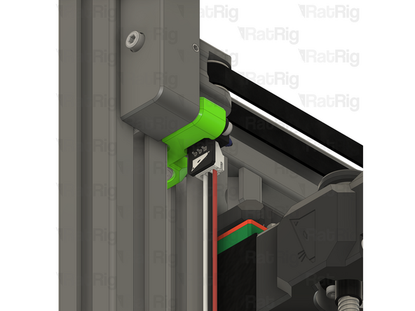
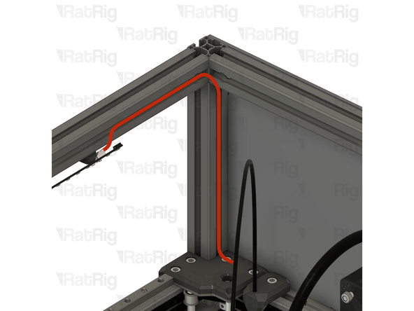
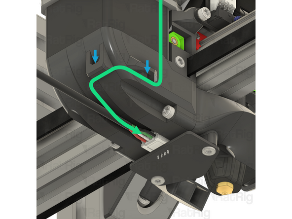
Route the cable as shown, passing it behind the stepper motor
-
Secure the cable within the extrusion slot using four of the 3030 wire clips
-
Do not fit any 3030 wire clips to the rear extrusion yet, they will be installed in a future step
-
-
-
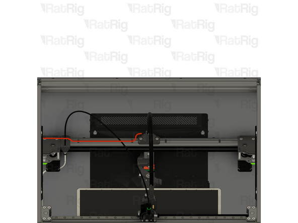
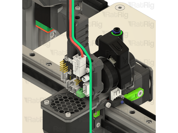
Route the cable as shown
-
Do not fit any 3030 wire clips to the rear extrusion yet, they will be installed in a future step
-
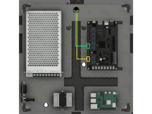
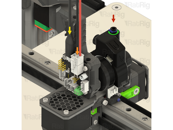
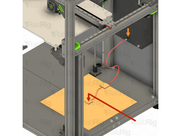
Pass the connector through the marked hole
-
Route the cable as shown
-
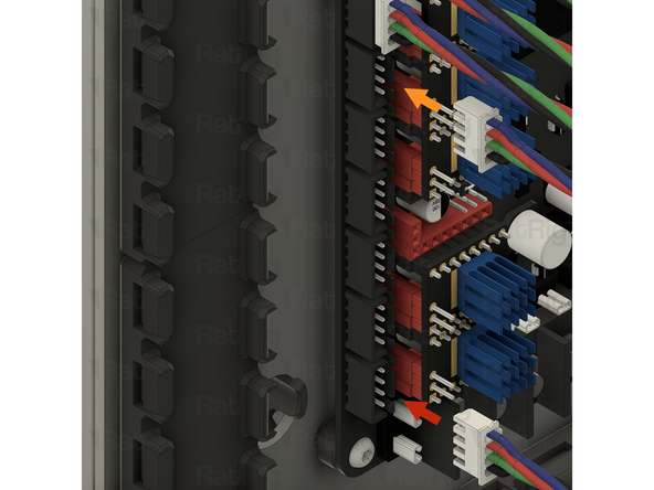
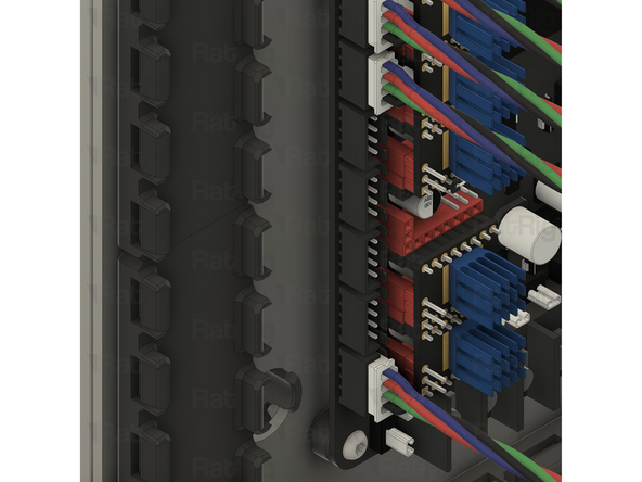
Connect the other end of the endstop cable to the marked socket on the Octopus motherboard
-
Make sure that you are using the correct cable and connect the correct end to the Octopus motherboard. The wire colours and order should match the image. Incorrect wiring can damage the endstop module and Octopus motherboard
-
-
-
The lengths and SKUs of the Z-axis stepper cables depend on which size of V-Core 4.0 is being assembled:
-
Rat Rig V-Core 4.0 300 or 400:
-
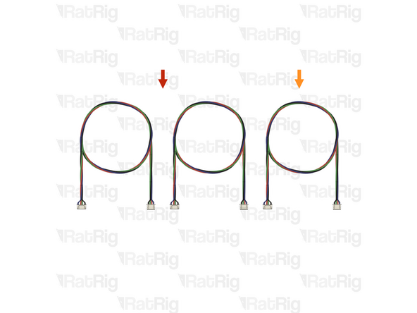
2x Cable 1500mm - 4 Conductor 24AWG - JST XH2.54 to JST PH6P (SKU: HW3026EC)
-
1x Cable 1000mm - 4 Conductor 24AWG - JST XH2.54 to JST PH6P (SKU: HW3025EC)
-
Rat Rig V-Core 4.0 500:
-
2x Cable 2000mm - 4 Conductor 24AWG - JST XH2.54 to JST PH6P (SKU: HW3027EC)
-
1x Cable 1500mm - 4 Conductor 24AWG - JST XH2.54 to JST PH6P (SKU: HW3026EC)
-
-
-
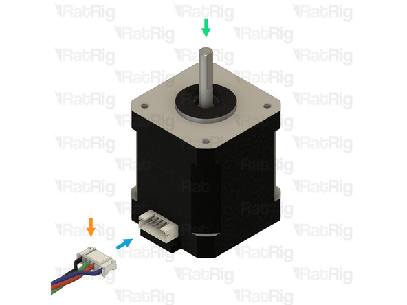
This step shows how to correctly connect a stepper motor cable to the stepper motor
-
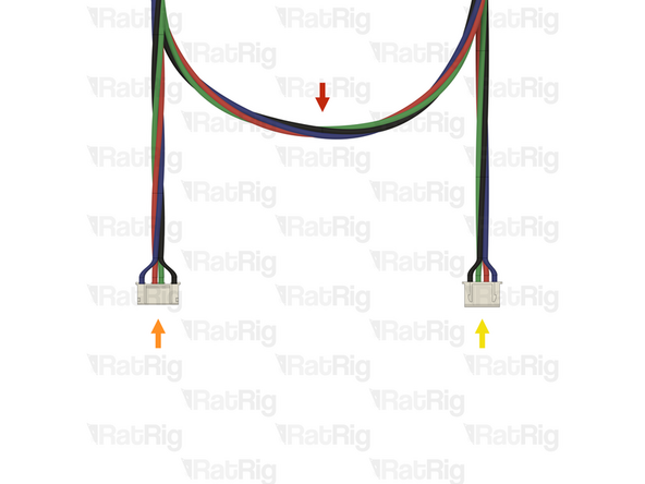
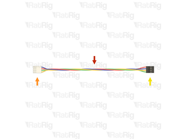
1x Stepper motor cable
-
The stepper motor cable has a different connector on each end:
-
1x Stepper motor connector - JST PH6P
-
1x Motherboard connector - JST XH4P
-
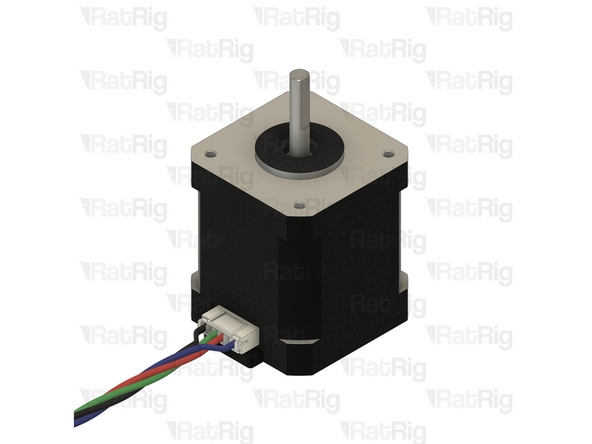
1x Example NEMA17 stepper motor
-
Make sure the connector is oriented correctly with the socket on the stepper motor. The key on the connector should align with the gap on the socket
-
-
-
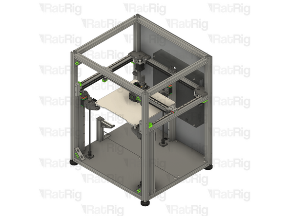
It is recommended to temporarily remove the bed assembly and lay the machine assembly on its front to make installation of the Z-axis stepper cables easier
-
It may be helpful to label the stepper motor cables to make it easier to keep track of which is which during the following steps
-
Connect a stepper motor cable to each front stepper motor
-
1500mm for a Rat Rig V-Core 4.0 300 or 400
-
2000mm for a Rat Rig V-Core 4.0 500
-
Connect a stepper motor cable to the rear stepper motor
-
1000mm for a Rat Rig V-Core 4.0 300 or 400
-
1500mm for a Rat Rig V-Core 4.0 500
-
-
-
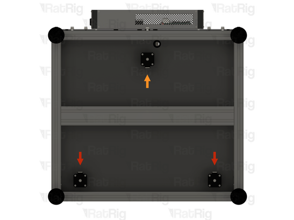
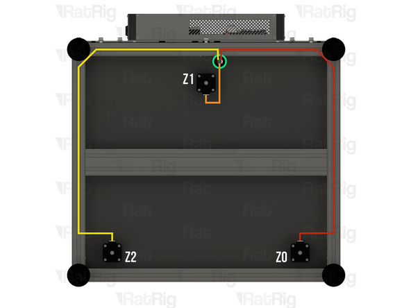
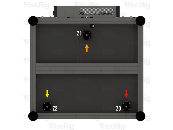
The three Z-axis stepper motors are labelled Z0, Z1 and Z2
-
Z0 is the front left stepper motor, when looking at the V-Core 4.0 from the front
-
Z1 is the rear stepper motor
-
Z2 is the front right stepper motor, when looking at the V-Core 4.0 from the front
-
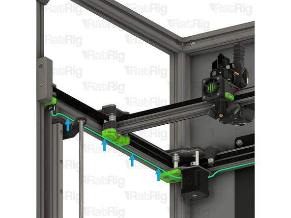
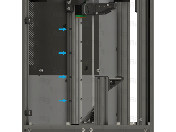
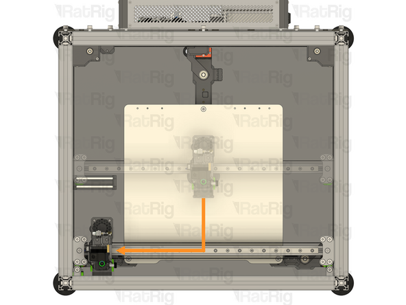
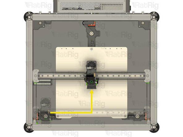
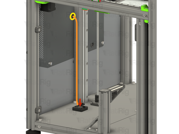
Route each stepper motor cable as shown
-
Pass all three connectors through the grommet in the base panel
-
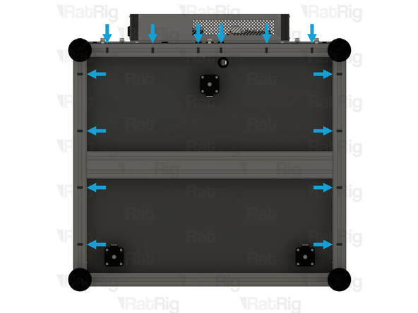
Secure the cables within the extrusion slot using fourteen of the 3030 wire clips in the marked locations
-
-
-
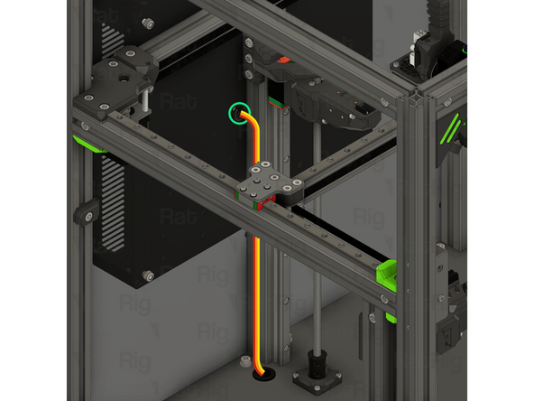
Stand the machine assembly back on its feet at this point, there should be no further need to access the underside
-
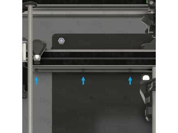
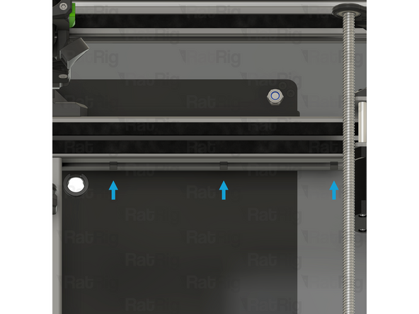
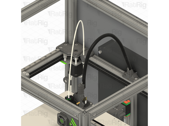
Route all three stepper motor cables upwards, inside the extrusion channel as shown
-
Z0 stepper motor cable
-
Z1 stepper motor cable
-
Z2 stepper motor cable
-
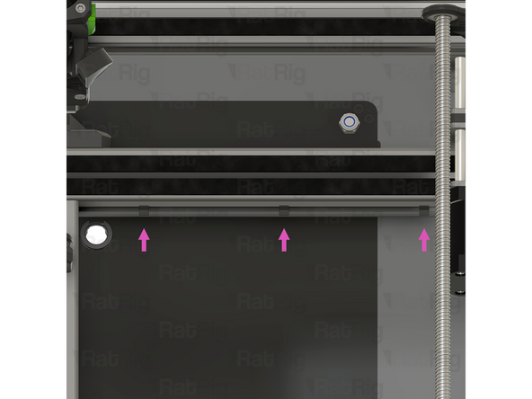
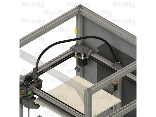
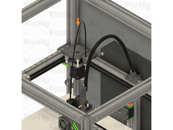
Pass all three connectors through the marked hole in the back panel
-
Secure the cables within the extrusion slot using four of the 3030 wire clips in the marked locations
-
-
-
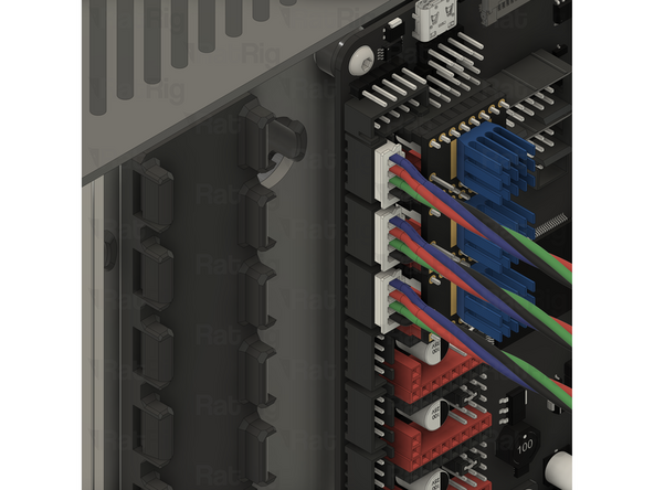
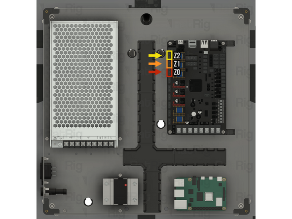
Route all three stepper motor cables inside the electronics enclosure, as shown
-
Z0 stepper motor cable
-
Z1 stepper motor cable
-
Z2 stepper motor cable
-
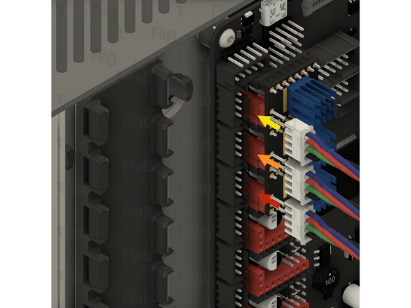
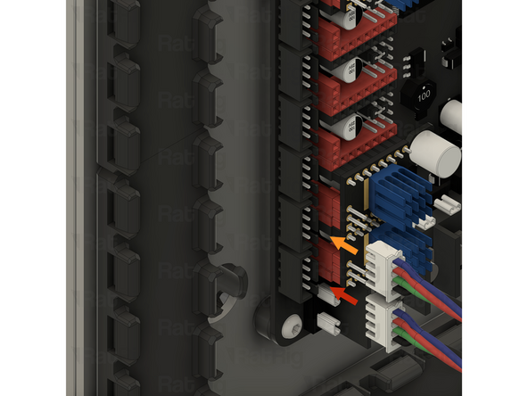
Connect each stepper motor cable to the Octopus motherboard
-
Z0 connects to driver 5, which is the third socket from the top
-
Z1 connects to driver 6, which is the second socket from the top
-
Z2 connects to driver 7, which is the top socket
-
-
-
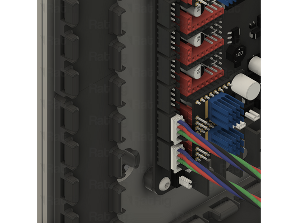
It is important to check the three Z-axis stepper motors are connected to the correct drivers on the Octopus motherboard. Failure to do so will cause issues with Z-tilt adjustment
-
Stepper Z0 is the front left stepper motor, when looking at the V-Core 4.0 from the front
-
It must be connected to driver 5 on the Octopus motherboard, which is the third socket from the top
-
Stepper Z1 is the rear stepper motor
-
It must be connected to driver 6 on the Octopus motherboard, which is the second socket from the top
-
Stepper Z2 is the front right stepper motor, when looking at the V-Core 4.0 from the front
-
It must be connected to driver 7 on the Octopus motherboard, which is the top socket
-
-
-
If you are building a CoreXY variant of the V-Core 4.0, then please continue following the next steps
-
If you are building a Hybrid or IDEX variant of the V-Core 4.0, then please skip to step 25
-
-
-
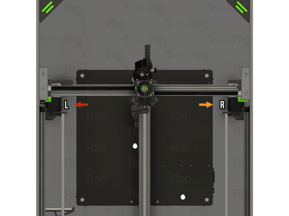
In the CoreXY configuration, there are only two stepper motors, simply labelled left and right
-
The left CoreXY stepper motor is on the left when looking at the V-Core 4.0 from the front
-
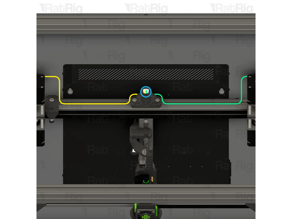
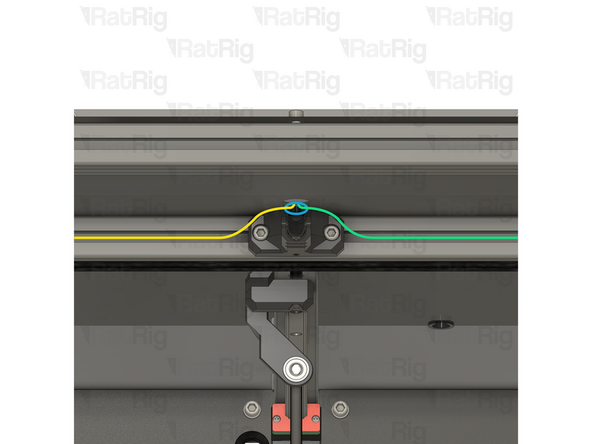
Route the left stepper motor cable as shown
-
Pass the connector and excess cable through the marked hole in the back panel
-
The right CoreXY stepper motor is on the right when looking at the V-Core 4.0 from the front
-
Route the right stepper motor cable as shown
-
Pass the connector and excess cable through the marked hole in the back panel
-
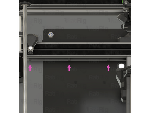
Secure the cables within the extrusion slot using six of the 3030 wire clips in the marked locations. On the left side, secure the Y-axis endstop cable along with the left stepper motor cable
-
-
-
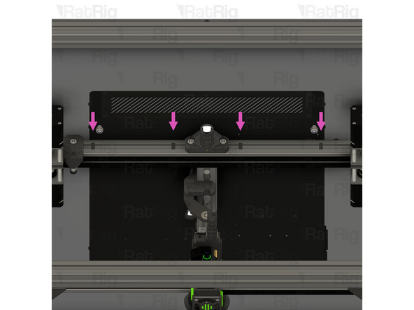
Route both stepper motor cables inside the electronics enclosure, as shown
-
Left CoreXY stepper motor cable
-
Right CoreXY stepper motor cable
-
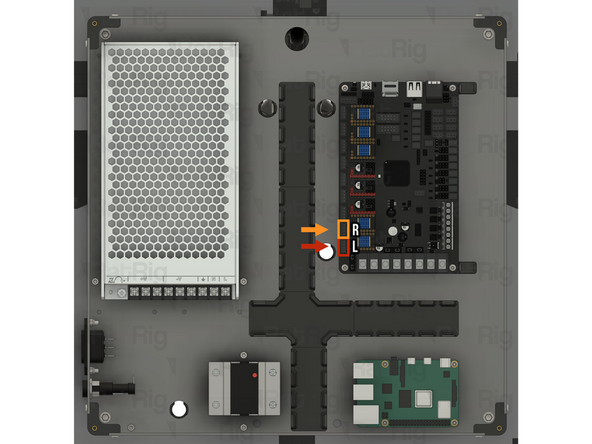
Connect each stepper motor cable to the Octopus motherboard
-
The left CoreXY stepper motor cable connects to driver 0, which is the bottom socket
-
The right CoreXY stepper motor cable connects to driver 1, which is the second socket from the bottom
-
-
-
It is important to check that both CoreXY stepper motors are connected to the correct drivers on the Octopus motherboard. Failure to do so will cause significant issues
-
The left stepper motor is on the left when looking at the V-Core 4.0 from the front
-
It must be connected to driver 0 on the Octopus motherboard, which is the bottom socket
-
The right stepper motor is on the right when looking at the V-Core 4.0 from the front
-
It must be connected to driver 1 on the Octopus motherboard, which is the second socket from the bottom
-
The next few steps are specific to the Hybrid and IDEX variants. If you are building the CoreXY variant, please skip to step 31
-
-
-
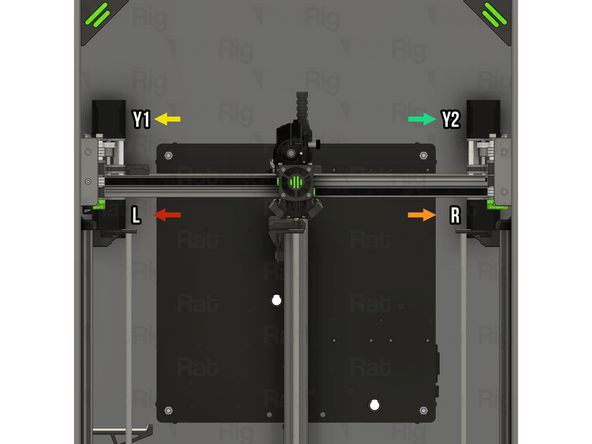
The Hybrid and IDEX variants of the V-Core 4.0 have four stepper motors:
-
The left stepper motor is on the bottom left when looking at the V-Core 4.0 from the front
-
The right stepper motor is on the bottom right when looking at the V-Core 4.0 from the front
-
The Y1 stepper motor is on the top left when looking at the V-Core 4.0 from the front
-
The Y2 stepper motor is on the top right when looking at the V-Core 4.0 from the front
-
-
-
It may be helpful to label the stepper motor cables to make it easier to keep track of which is which during the following steps
-
Route the left stepper motor cable as shown
-
Pass the connector and excess cable through the marked hole in the back panel
-
Route the right stepper motor cable as shown
-
Pass the connector and excess cable through the marked hole in the back panel
-
Secure the cables within the extrusion slot using six of the 3030 wire clips in the marked locations. On the left side, secure the Y-axis endstop cable along with the left stepper motor cable
-
-
-
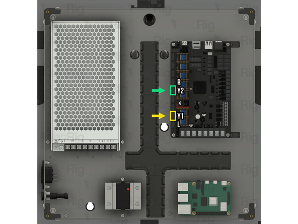
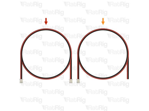
Route the Y1 stepper motor cable as shown
-
Route the Y2 stepper motor cable as shown
-
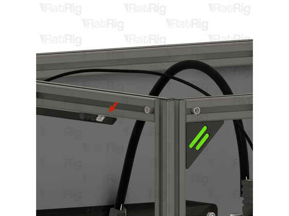
Route both stepper motor cables behind the umbilical mount, as shown
-
Pass both connectors and all excess cable through the marked hole in the back panel
-
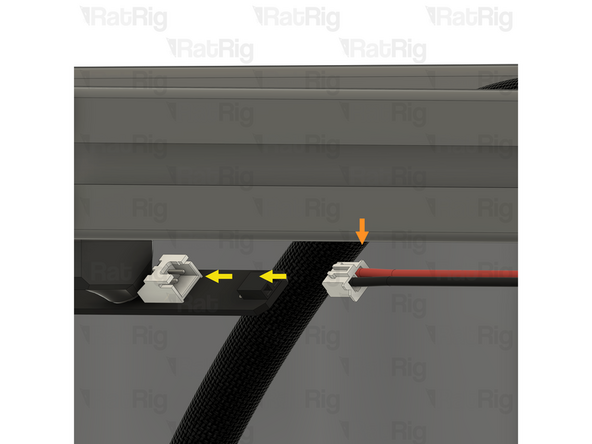
Secure the cables within the extrusion slot using four of the 3030 wire clips in the marked locations
-
-
-
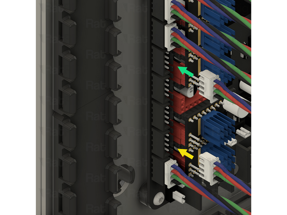
Route the left and right stepper motor cables inside the electronics enclosure, as shown
-
Left CoreXY stepper motor cable
-
Right CoreXY stepper motor cable
-
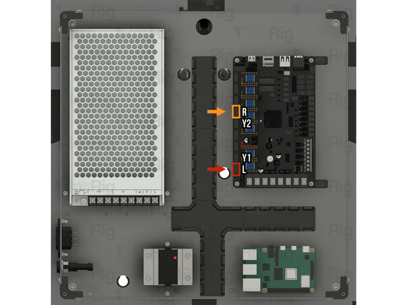
Connect each stepper motor cable to the Octopus motherboard
-
The left stepper motor cable connects to driver 0, which is the bottom socket
-
The right CoreXY stepper motor cable connects to driver 3, which is the forth socket from the top
-
-
-
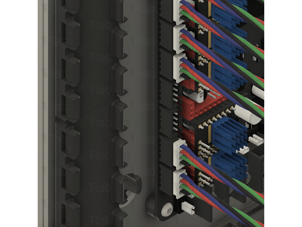
Route the Y1 and Y2 stepper motor cables inside the electronics enclosure, as shown
-
Y1 stepper motor cable
-
Y2 stepper motor cable
-
Connect each stepper motor cable to the Octopus motherboard
-
The Y1 stepper motor cable connects to driver 1, which is the second socket from the bottom
-
The Y2 stepper motor cable connects to driver 3, which is the fifth socket from the top
-
-
-
It is important to check that all four stepper motors are connected to the correct drivers on the Octopus motherboard. Failure to do so will cause significant issues
-
The left stepper motor is on the bottom left when looking at the V-Core 4.0 from the front
-
It must be connected to driver 0 on the Octopus motherboard, which is the bottom socket
-
The right stepper motor is on the bottom right when looking at the V-Core 4.0 from the front
-
It must be connected to driver 3 on the Octopus motherboard, which is the forth socket from the top
-
-
-
It is important to check that all four stepper motors are connected to the correct drivers on the Octopus motherboard. Failure to do so will cause significant issues
-
The Y1 stepper motor is on the top left when looking at the V-Core 4.0 from the front
-
It must be connected to driver 1 on the Octopus motherboard, which is the second socket from the bottom
-
The Y2 stepper motor is on the top right when looking at the V-Core 4.0 from the front
-
It must be connected to driver 3 on the Octopus motherboard, which is the fifth socket from the top
-
-
-
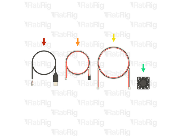
1x Prepared LED-to-LED cable from the Preparations guide
-
1x Prepared LED-to-Octopus cable from the Preparations guide
-
-
-
Rat Rig V-Core 4.0 LED strip assembly - Left side
-
Prepared LED-to-LED cable
-
Connect one end of the LED-to-LED cable to the front JST connector on the left LED strip, as shown
-
-
-
Route the LED-to-LED power cable around the inside of the V-Core 4.0 frame, within the extrusion slot, as shown
-
Rat Rig V-Core 4.0 LED strip assembly - Right side
-
Connect the other end of the LED-to-LED cable to the front JST connector on the right LED strip, as shown
-
-
-
Rat Rig V-Core 4.0 LED strip assembly - Left side
-
LED-to-Octopus cable
-
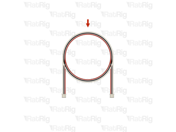
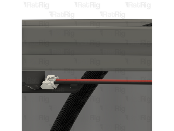
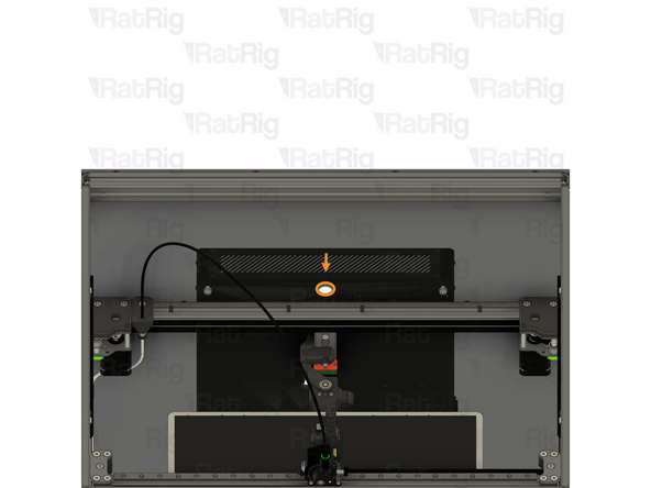
Connect one end of the LED-to-Octopus cable to the back JST connector on the left LED strip, as shown
-
Make sure that the black wire is on the left and the red wire is on the right, as shown
-
-
-
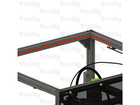
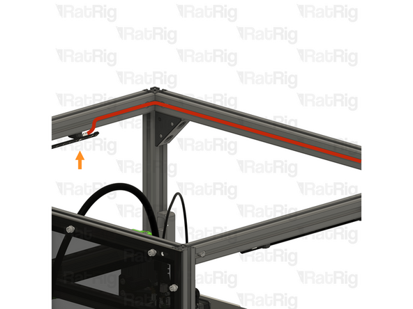
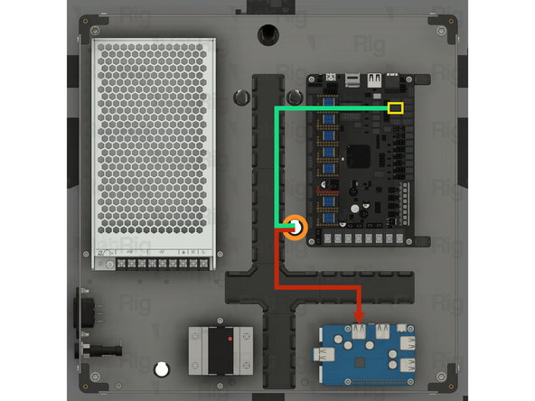
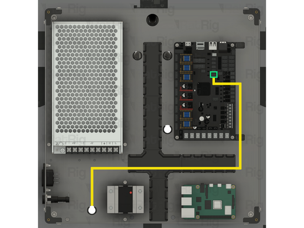
Route the LED-to-Octopus power cable around the inside of the V-Core 4.0 frame, within the extrusion slot, as shown
-
Pass the end of the cable through the hole in the panel and into the electronics enclosure
-
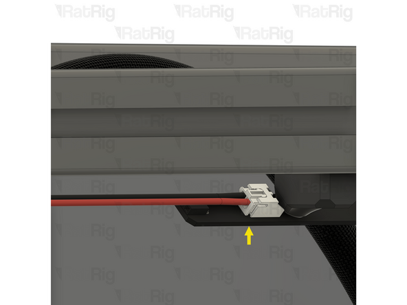
Use the 3030 cable clips to secure the cable to the extrusions
-
-
-
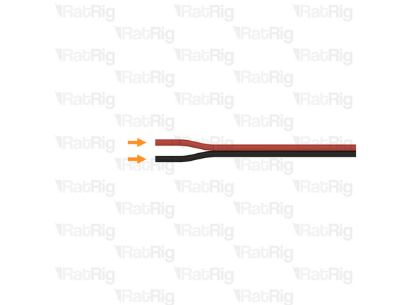
Route the LED-to-Octopus power cable as shown
-
Gently separate roughly 15mm of the two conductors by gripping each and pulling them apart as shown
-
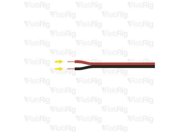
Strip 5mm of the insulation from both conductors on the end of the wire
-
-
-
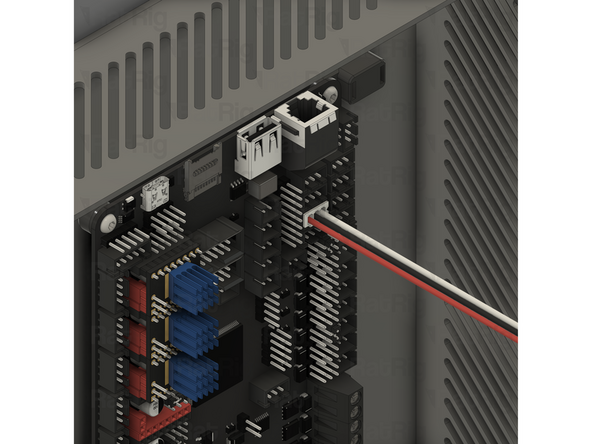
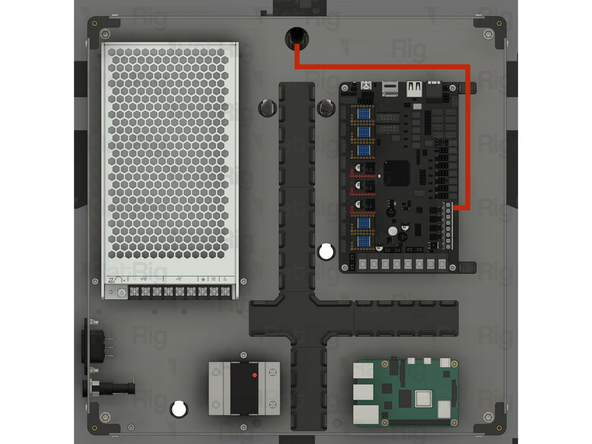
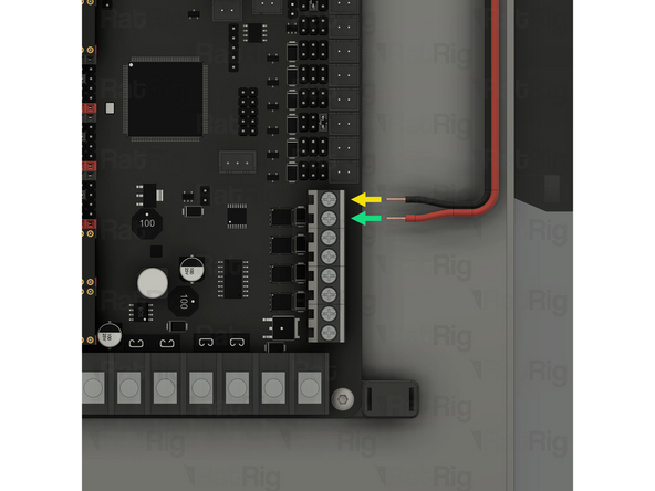
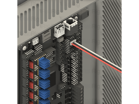
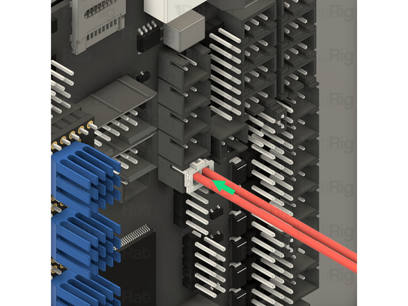
Locate the marked wire terminal on the Octopus
-
Loosen the two marked screws
-
Insert the stripped end of the black wire into the top slot of the connector
-
Insert the stripped end of the red wire into the bottom slot of the connector
-
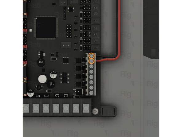
Tighten both screws to secure the wire into the terminal
-
After tightening the screws, gently pull each wire to make sure they are fully secured in the terminal. Also check that there are no loose strands of wire which might cause a short circuit
-
If the cable comes out, loosen the screw, reinsert the cable and tighten the screw before trying again
-
-
-
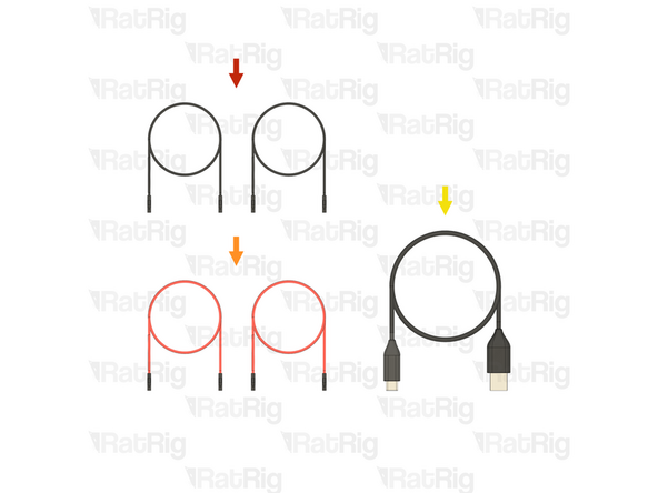
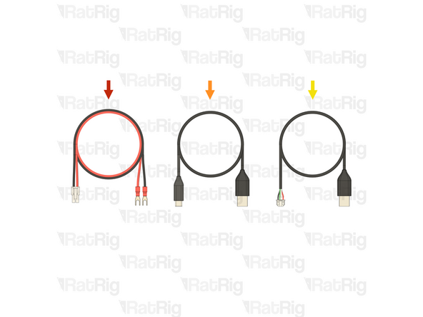
2x Cable - DC Power - 22AWG BLACK - 500mm - (A-Dupont B-Dupont) (SKU: HW3829EC)
-
2x Cable - DC Power - 22AWG RED - 500mm - (A-Dupont B-Dupont) (SKU: HW3830EC)
-
1x USB-A to USB-C cable from step 40 of the Electronics guide
-
-
-
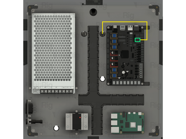
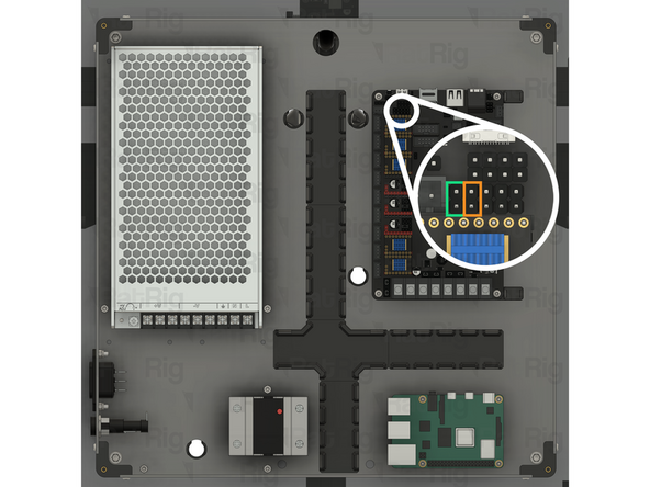
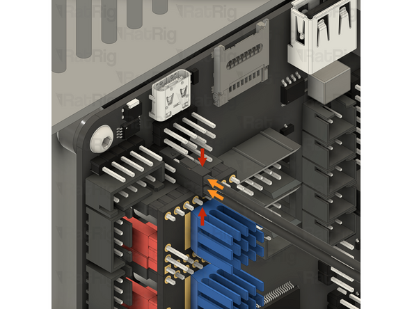
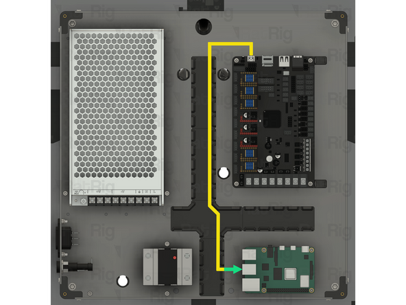
Locate the marked 2x5 pin header on the Octopus motherboard
-
Cable - DC Power - 22AWG BLACK - 500mm - (A-Dupont B-Dupont)
-
Connect both of the black Raspberry Pi power cables to the Octopus motherboard as shown
-
One black Raspberry Pi power cable should be connected to the top pin, second from the left and the other to the bottom pin, second from the left
-
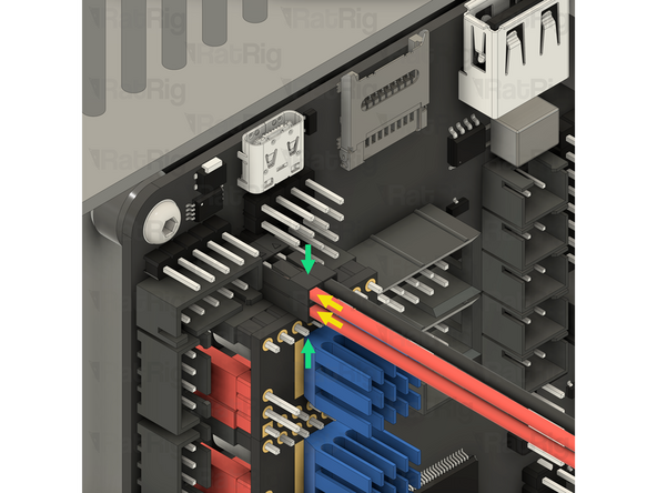
Cable - DC Power - 22AWG RED - 500mm - (A-Dupont B-Dupont)
-
Connect both of the red Raspberry Pi power cables to the Octopus motherboard as shown
-
One red Raspberry Pi power cable should be connected to the top leftmost pin and the other to the bottom leftmost pin
-
Before continuing, verify that all four Raspberry Pi power cables are correctly connected. Failure to do so will cause irreparable damage to components
-
-
-
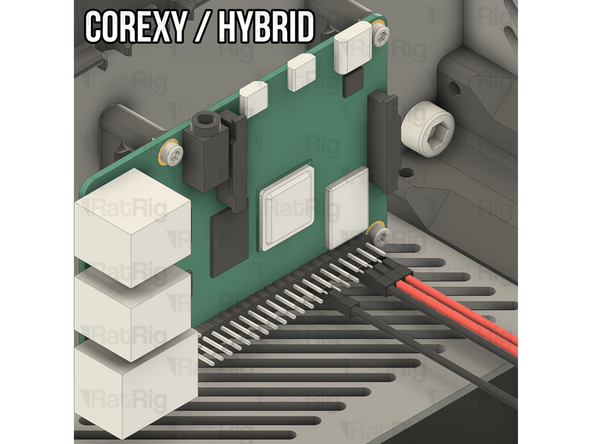
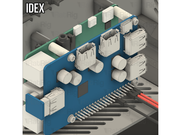
Locate the marked GPIO header on the Raspberry Pi or Waveshare USB hat
-
The power connections for the Raspberry Pi are the same regardless of which variant of V-Core 4.0 you are building. If building the IDEX variant, the connections are made to the GPIO header on the Waveshare USB hat instead of directly to the Raspberry Pi GPIO header
-
Connect one of the red Raspberry Pi power wires to the rightmost pin on the bottom row of the GPIO header
-
Connect the second of the red Raspberry Pi power wires to the second pin from the right, on the bottom row of the GPIO header
-
Connect one of the black Raspberry Pi power wires to the third pin from the right, on the bottom row of the GPIO header
-
Connect the second of the black Raspberry Pi power wires to the seventh pin from the right, on the bottom row of the GPIO header
-
Before continuing, verify that all four Raspberry Pi power cables are correctly connected. Failure to do so will cause irreparable damage to components
-
-
-
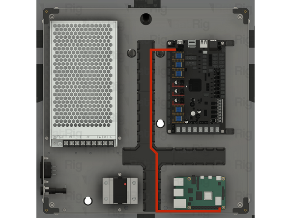
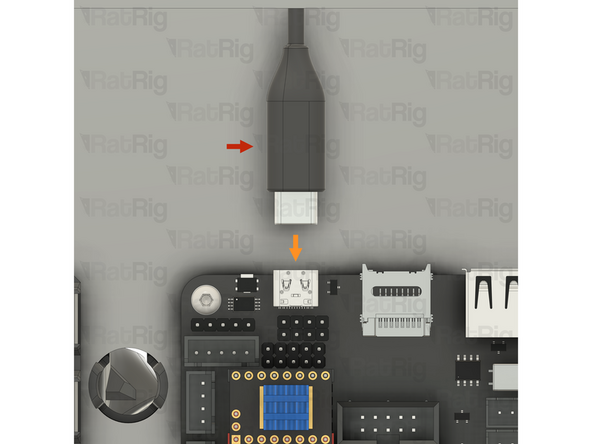
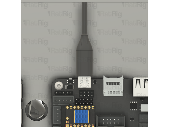
USB-A to USB-C cable
-
Connect the USB-C end of the cable to the Octopus motherboard
-
Route the USB-A to USB-C cable as shown
-
Connect the USB-A end of the cable to any available port of the Raspberry Pi
-
-
-
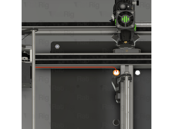
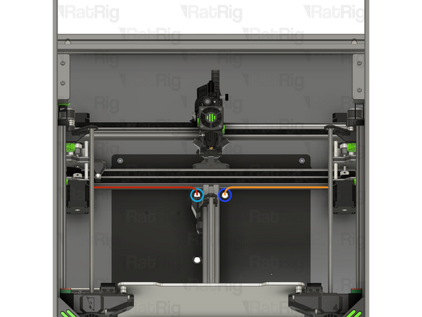
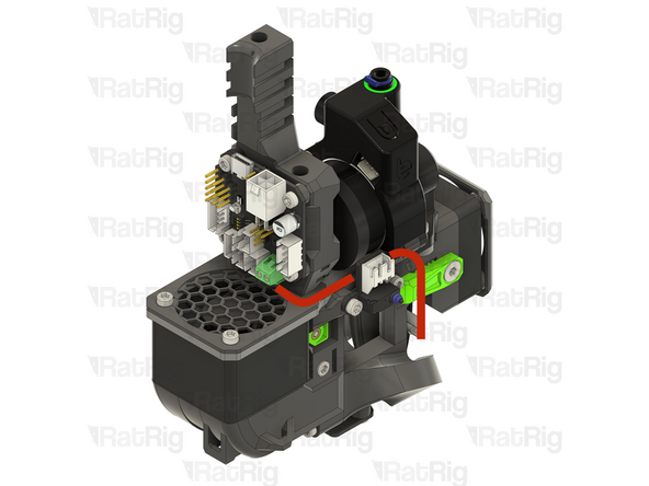
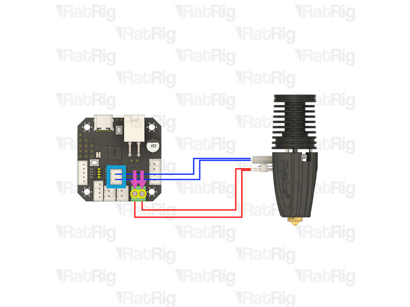
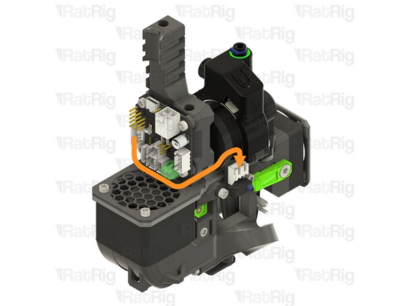
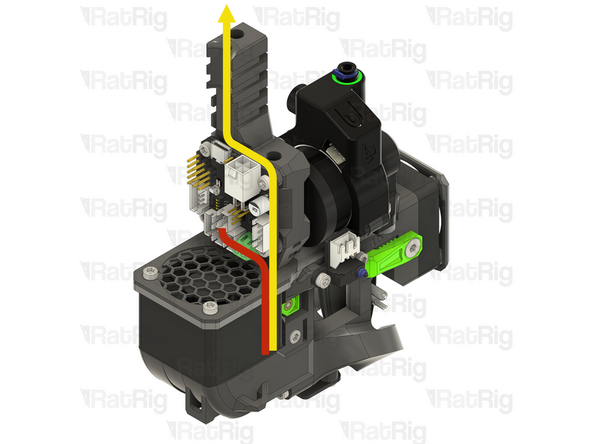
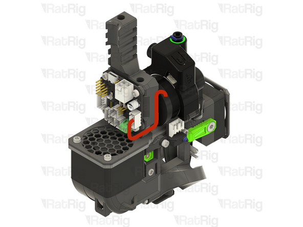
Route the Phaetus Rapido hotend wiring to the toolboard as shown, passing behind the endstop
-
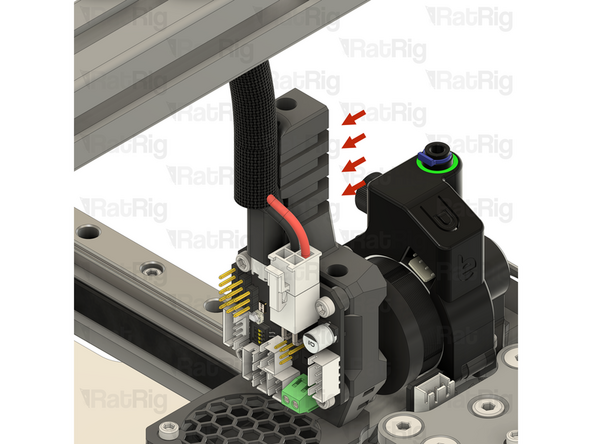
Install a jumper (found in the toolboard box) onto the marked pins to enable accurate hotend temperature readings
-
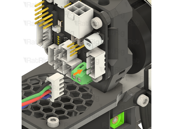
Loosen the two marked screws
-
Insert each of the stripped hotend heater wires (shown in red) into a separate slot of the connector, then tighten the screws to secure the wires into the terminal
-
Due to the limited space, it may be easier to temporarily remove the toolboard from the toolhead to install the hotend heater wires
-
After tightening the screws, gently pull each wire to make sure they are fully secured in the terminal. Also check that there are no loose strands of wire which might cause a short circuit
-
If either wire comes out, loosen the screw, reinsert the wire, and try again after tightening
-
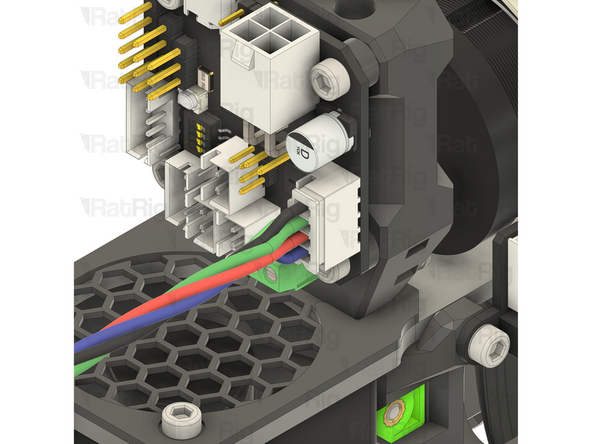
Connect the JST connector on the thermistor wiring (shown in blue) to the marked connector on the toolboard
-
-
-
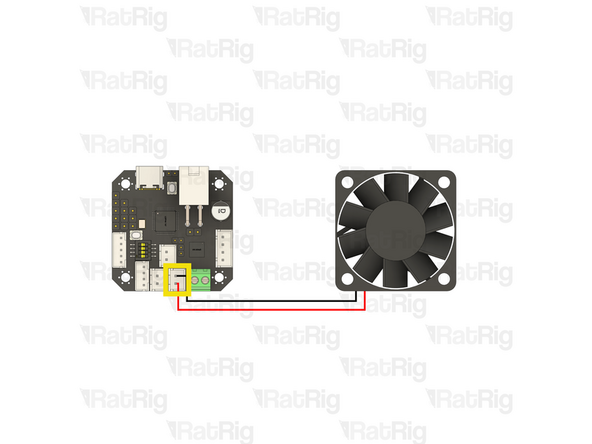
Route the hotend fan wiring to the toolboard as shown
-
Use cable ties to secure the hotend fan cable to the toolhead
-
Connect the JST connector on the hotend fan wiring, to the marked connector on the toolboard
-
Before continuing, verify that the black wire from the hotend fan is connected to the upper pin of the connector and that the red wire from the hotend fan is connected to the lower pin. Incorrect wiring will cause irreparable damage to components
-
-
-
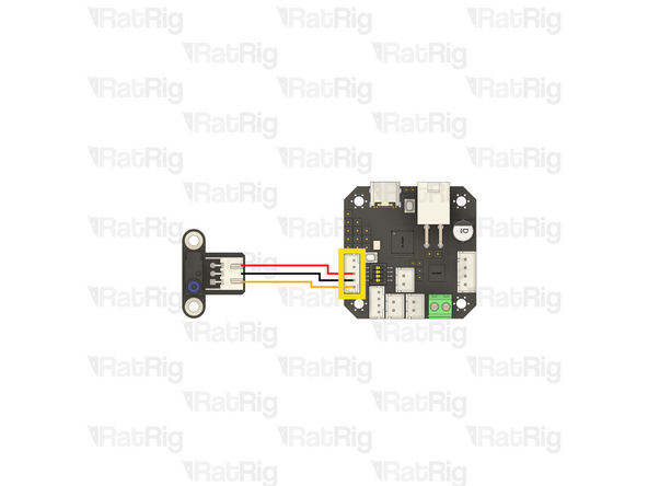
Prepared toolhead endstop cable from the Preparations guide
-
Connect the 3 pin JST connector to the endstop
-
Route the endstop wiring to the toolboard as shown
-
Connect the 5 pin JST connector to the marked connector on the toolboard
-
-
-
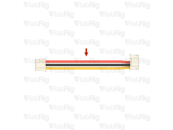
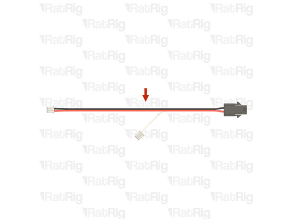
Prepared 4028 part cooling fan extension cable from the Preparations guide
-
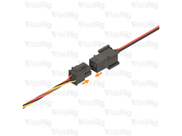
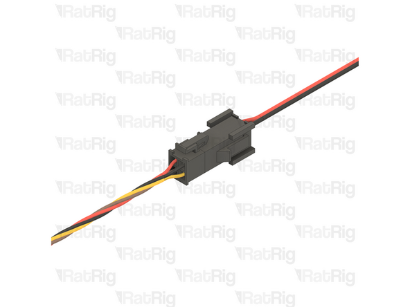
Connect the 4028 part cooling fan extension cable to the 4028 part cooling fan
-
The Molex connectors will only fit together one way and will lock together
-
-
-
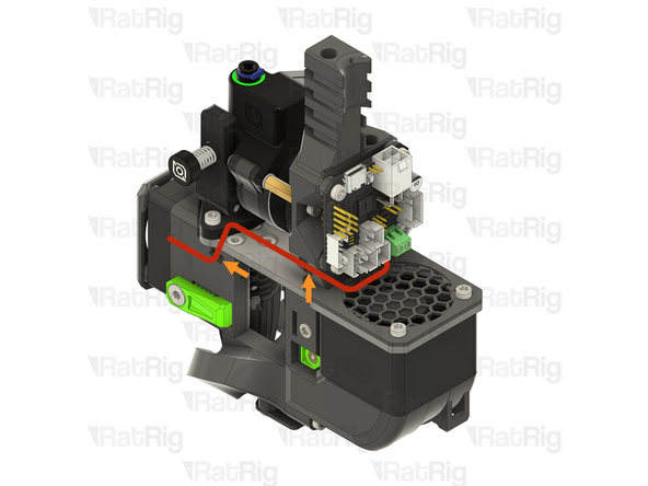
Route the single white wire on the 4028 part cooling fan extension cable to the toolboard as shown
-
In the wiring diagram, the white wire is depicted as grey for clarity
-
Connect the JST connector on the white wire, to the marked connector on the toolboard
-
Before continuing, verify that the white wire from the 4028 part cooling fan extension is connected to the upper pin of the connector. Incorrect wiring will cause irreparable damage to components
-
Route the red and black wires on the 4028 part cooling fan extension cable back to the electronics enclosure, passing through the umbilical hole in the back panel
-
Do not worry about managing the cables from the toolhead yet, they will be managed and wrapped later in the guide
-
-
-
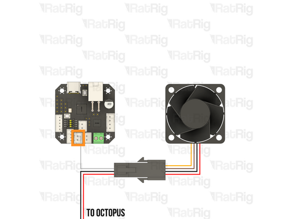
Route the 4028 part cooling fan extension cable as shown
-
Connect the end of the cable to the marked socket on the Octopus motherboard
-
Please note: If you are building an IDEX variant of the V-Core 4.0, there will be two 4028 part cooling fan power cables
-
Install one in each of the marked sockets on the Octopus motherboard. It does not matter which cable goes in which of the marked sockets as they are both always-on 12V power
-
-
-
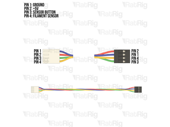
Prepared Orbiter smart sensor cable from the Preparations guide
-
The Orbiter smart sensor cable has two different connectors:
-
The white Molex connector
-
The black Dupont connector
-
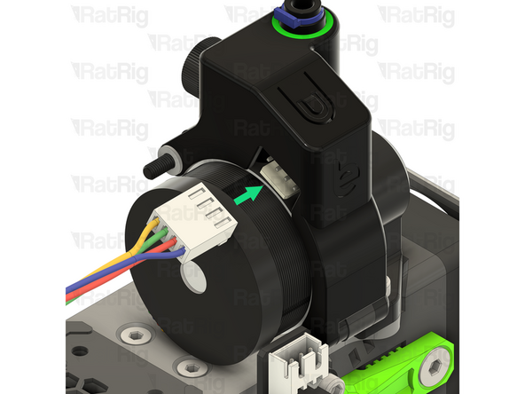
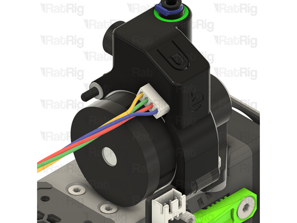
Connect the white Molex connector to the connector on the Orbiter smart sensor
-
Some components of the toolhead have been hidden for clarity
-
-
-
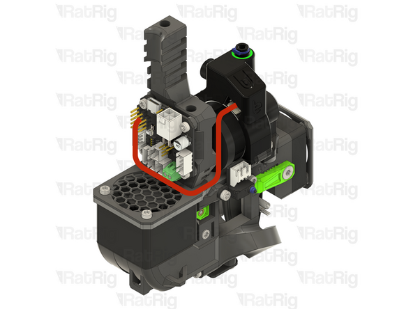
Route the Orbiter smart sensor cable as shown
-
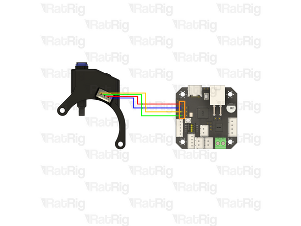
Connect the 4 pin Dupont connector to the marked connector on the toolboard
-
Please note: The wiring colour shown may not match your Orbiter smart sensor harness. It is very important to use the provided wiring diagram to correctly connect the cable. Do not blindly follow the wire colours
-
Incorrect wiring will cause irreparable damage to components
-
-
-
Route the Orbiter extruder stepper motor cable as shown
-
Connect the extruder stepper motor to the toolboard
-
Excess cable from the extruder stepper motor can be managed with cable ties
-
-
-
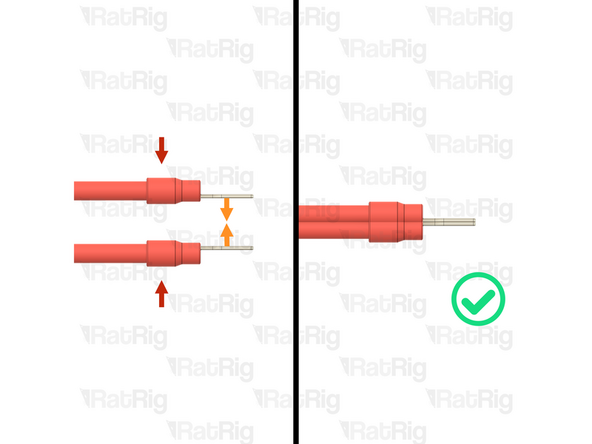
Due to the limited number of available PSU terminals, it is required to "double up" some of the connections
-
Fork terminals
-
Orient the fork terminals "back to back" as shown
-
Power supply terminal
-
Loosen the screw on the power supply terminal and insert the two fork terminals as shown
-
Fasten the screw on the power supply terminal to secure the fork terminals
-
After tightening the screws, gently pull fork terminals to make sure they are fully secured to the power supply
-
If either fork terminal comes out, loosen the screw, reinsert the terminals, and try again after tightening
-
-
-
1x Prepared toolboard power wiring from the Preparations guide
-
1x Cable - USB-A to USB-C Cable 1500mm (SKU: HW3907EC)
-
1x Cable - USB-A to Beacon (Included with the Beacon Sensor - SKU: HW3849EC)
-
-
-
Prepared toolboard power wiring from the Preparations guide
-
Insert the fork terminal on the red wire into any of the three terminals marked by the [ +V ] symbol on the power supply. Secure the fork terminal by tightening the screw
-
Insert the fork terminal on the black wire into any of the three terminals marked by the [ -V ] symbol on the power supply. Secure the fork terminal by tightening the screw
-
Refer to step 52 for help on installing two fork terminals into a single power supply terminal
-
Route the toolboard power wires as shown, passing the white connector through the hole in the electronics enclosure and panel
-
Connect the USB-A end of USB-A to USB-C cable to any available USB port on the Raspberry Pi and route the cable as shown
-
Connect the USB-A end of USB-A to Beacon cable to any available USB port on the Raspberry Pi and route the cable as shown
-
Pass both of the connectors of the USB cables through the hole in the electronics enclosure and panel
-
-
-
V-Core 4 toolhead
-
If you are building an IDEX variant of the V-Core 4.0, this is the left toolhead when viewed from the front
-
Connect the white Molex Micro-Fit connector on the toolhead wiring to the EBB42 toolboard as shown
-
Connect the USB-C end of the USB-A to USB-C cable to the toolboard as shown
-
Connect the Beacon end of the USB-A to Beacon cable, to the connector on the Beacon probe, then route the cable around the toolhead as shown
-
Secure the USB-A to Beacon cable to the toolhead using cable ties at the points marked
-
-
-
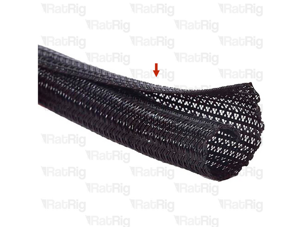
1 metre of Cable Sleeve - Black 10mm split braided sleeve (SKU: HW2088EC)
-
It is recommended to perform the next steps with the toolhead moved to the the front left corner, as this ensures all toolhead wiring will be long enough to reach the whole print area
-
Be careful not to push the toolhead too far against the end of the end of the X-axis gantry as you can damage the X-axis endstop
-
If you are building an IDEX variant of the V-Core 4.0, put one toolhead in the front left and the other in the front right
-
Route the toolhead cables along the previously installed piano wire and wrap the cable sleeve around both the cables and the piano wire, leading all the way back to the electronics enclosure
-
-
-
Secure all four toolhead cables (Toolboard USB, Toolboard Power, Beacon and 4028 part cooling fan power) to the umbilical mount on the toolhead, using cable ties
-
If you are building a CoreXY or Hybrid variant of the V-Core 4.0, secure the umbilical to the frame mount at this stage
-
If you are building an IDEX variant of the V-Core 4.0, do not fasten the umbilical to the frame until both toolheads have been wired and cable managed. Then secure both of the umbilicals to the mount
-
Move the toolhead(s) back to the middle of the print area
-
Please note: If you are building an IDEX variant of the V-Core 4.0, repeat all steps beginning at step 43, to wire the second toolhead. The second IDEX toolhead does not have a Beacon probe, so skip any instructions relating to it
-
-
-
1.2 metre of Cable Sleeve - Black 5mm split braided sleeve (SKU: HW3884EC)
-
The V-Core 4.0 kit is provided with some smaller cable sleeve that can optionally be used to sleeve the white PTFE tube from the toolhead
-
If you are building an IDEX, remember to sleeve both PTFE tubes
-
-
-
If you are building a CoreXY or Hybrid variant of the V-Core 4.0, you can now skip to step 64
-
If you are building an IDEX variant of the V-Core 4.0, then please continue following the next steps
-
-
-
1x Cable - USB-A to Rat Rig VAOC Camera (SKU: HW4003EC)
-
1x Cable 1000mm - 3 Conductor 24AWG - JST PH2.0 to Dupont 2.54 (VAOC LED) (SKU: HW4094EC)
-
1x Cable 1500mm - 3 Conductor 24AWG - JST XH2.54 to JST XH2.54 (Endstop pin out) (SKU: HW3029EC)
-
1x Fan - 40mm Axial Brushless 24V DC - 1500mm Cable - GDSTime High Quality (Double Ball Bearing) (SKU: HW2815EC)
-
-
-
The necessary VAOC wiring will be performed in the next steps so that it is ready for the assembly and installation of the VAOC module in a later chapter
-
Connect the USB-A end of the USB-A to Rat Rig VAOC Camera cable to any available USB port on the Raspberry Pi (or USB hub hat) and route the cable as shown
-
Pass the other end of the cable through the marked hole
-
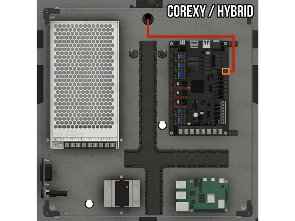
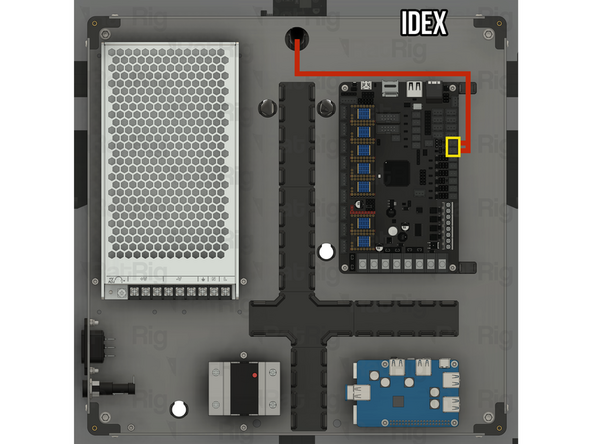
Connect one end of the 1500mm - 3 Conductor 24AWG - JST XH2.54 to JST XH2.54 (Endstop pin out) cable to the marked connector on the Octopus motherboard
-
Route the remainder of the cable as shown
-
Pass the other end of the cable through the marked hole
-
-
-
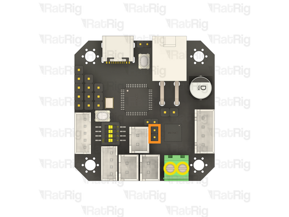
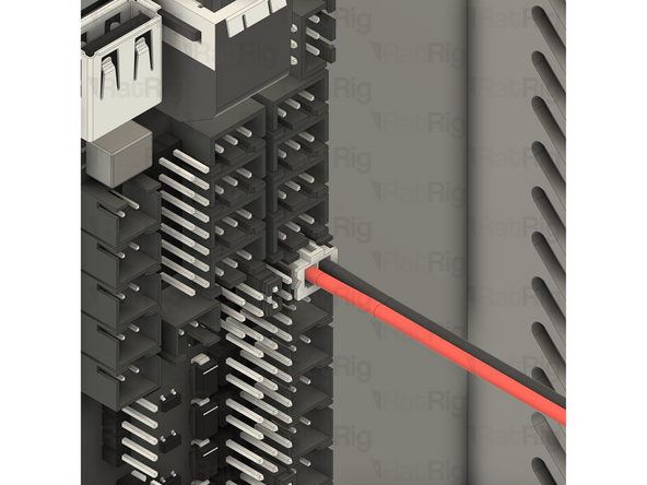
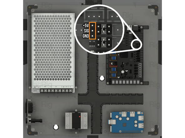
Locate the marked 1x3 pin header on the Octopus motherboard
-
Cable 1000mm - 3 Conductor 24AWG - JST PH2.0 to Dupont 2.54 (VAOC LED)
-
Connect the Dupont end of the cable to the Octopus motherboard, as shown
-
Make sure that the Dupont connector is oriented as shown. The red wire should be at the top, white in the middle and black at the bottom
-
Route the remainder of the cable as shown
-
Pass the other end of the cable through the marked hole
-
-
-
Fan - 40mm Axial Brushless 24V DC - 1500mm Cable - GDSTime High Quality (Double Ball Bearing)
-
Sit the fan on the baseplate of the V-Core 4.0 assembly for now
-
Route the fan wiring as shown
-
Pass the connector on the fan wiring through the hole in the back panel and into the electronics enclosure
-
Route the VAOC fan cable as shown
-
Connect the end of the cable to the marked socket on the Octopus motherboard
-
Optional: It is recommended, but not required, to assemble the IDEX accessories at this point
-
Follow the IDEX accessories guide, then return to complete the remaining steps here
-
-
-
21x Electronics Wire Guide Clip - Nylon Injection Part (SKU: HW3847GC)
-
The electronics wire guide clips hook on to one side of the wire guide printed parts
-
Then rotate and click into place
-
Install all 21 electronics wire guide clips to secure all of the wiring in place
-
If you need to remove one, or all, of the electronics wire guide clips, insert a thin, flat object into the small pocket on the side of the clip, then gently pry that end to unclip it from the wire guide
-
Be careful not to trap or pinch any cables when installing the wire guide clips
-
-
-
It is necessary, for initial testing and commissioning, to connect the the bed heater thermistor to the Octopus motherboard. Do not install the bed heater, or the magnetic print sheet to the bed at this point, they will be installed during the commissioning guide
-
Keenovo Silicone Heater Bed Pad w/ NTC 100K Thermistor and Thermal Fuse (Note: The SKU varies based on voltage and size)
-
110V Variants (300, 400, 500): HW2766EK, HW2767EK, HW2768EK
-
220V Variants (300, 400, 500): HW2349EC, HW2350EC, HW2351EC
-
Set the bed heater on the baseplate, inside the V-Core 4.0 assembly
-
Feed the bed heater thermistor cable through the marked hole in the back panel and into the electronics enclosure, leaving the other 2 wires coming from the bed heater where they are
-
Route the bed heater thermistor cable as shown. Do not worry about cable managing it at this point
-
Connect the 2 pin JST connector on the bed heater thermistor, to the marked connector on the Octopus motherboard
-
-
-
Before proceeding with any of the line voltage (110V / 220V AC) wiring, it is crucial to understand the risks involved
-
Line voltage wiring is dangerous and should always be performed by a competent person. This is a crucial safety measure to prevent electrical hazards and ensure the work is carried out safely and correctly. Line voltage can cause significant injury, or even death if handled improperly
-
Always make sure the machine is unplugged and that any capacitors (such as inside the power supply) have had time to discharge before performing any maintenance. NEVER work on the machine whilst it is plugged in
-
Additional warning for counties with 110V line voltage:
-
Ensure the power cable you are using is certified and rated for a continuous current of 15A or higher. If you are unsure which power cable to use, consult a professional or certified electrician
-
-
Note: Do not connect the silicone bed heater to the power supply or solid state relay at this point. It will be wired during the commissioning guide
-
Continue to the next step once the line voltage wiring is complete
-
-
-
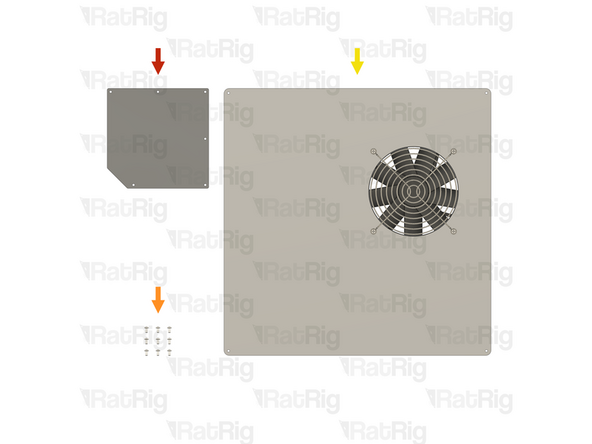
1x Rat Rig V-Core 4.0 - Electronics AC Cover v1.0 (SKU: HW3788GC)
-
9x Button Head Screw M3 (Single) (Length: 6mm) (SKU: HW1337SC)
-
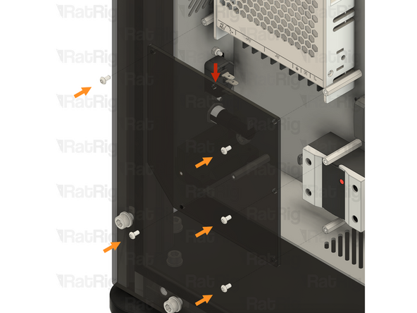
1x Prepared Electronics Enclosure Lid Assembly from step 59 of the Electronics guide
-
-
-
Rat Rig V-Core 4.0 - Electronics AC Cover v1.0
-
Position the AC cover over the AC wiring, aligning the holes in the cover with the hex standoffs
-
Be careful not to trap or pinch any cables when installing the AC cover
-
5x Button Head Screw M3 (Single) (Length: 6mm)
-
Insert an M3x6 Button Head Screw into each of the five holes shown on the cover, threading and tightening them into the hex standoffs beneath
-
Be careful not to overtighten the screws as you can damage the AC cover
-
-
-
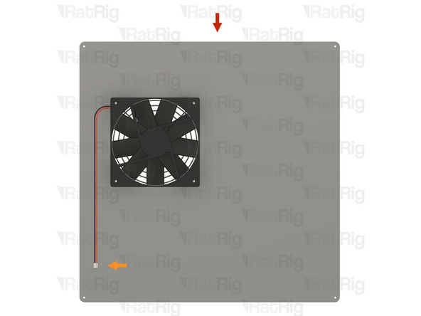
Prepared Electronics Enclosure Lid Assembly from step 59 of the Electronics guide
-
Fan - 120x15 Axial 24V - JST-2 Power Connector
-
Connect the fan connector to the marked socket on the Octopus motherboard
-
-
-
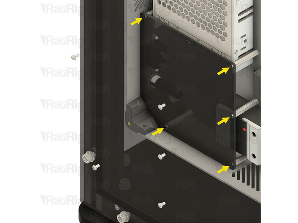
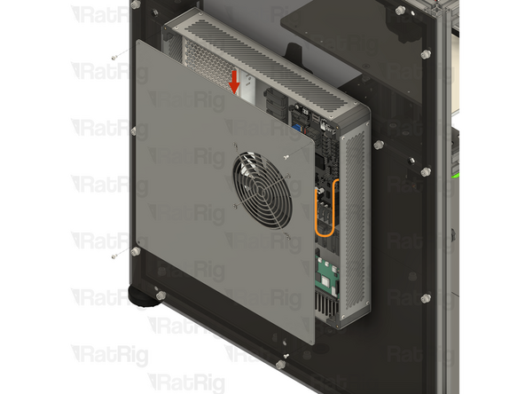
Align the lid with the electronics enclosure
-
Make sure the cable for the 120x15mm fan is clear of the fan blades
-
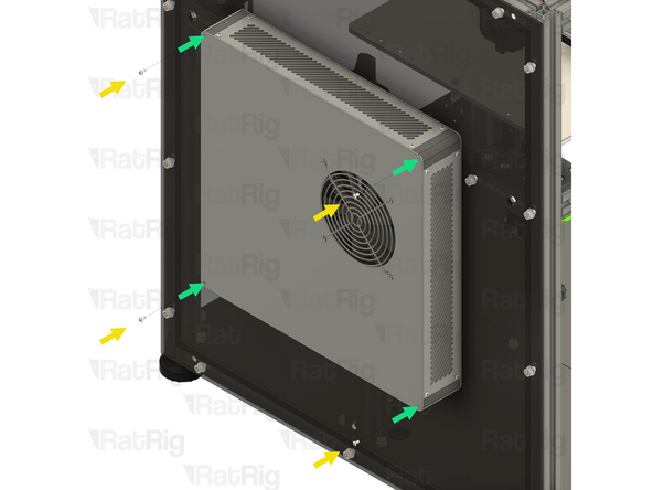
4x Button Head Screw M3 (Single) (Length: 6mm)
-
Insert an M3x6 Button Head Screw into each of the four marked holes on the cover, threading and tightening them into the electronics enclosure
-
Be careful not to overtighten the screws as you can damage the printed parts
-
-
-
The next guide to follow will depend on your specific V-Core 4.0 configuration:
-
If you are building an IDEX variant of the V-Core 4.0:
-
Firstly follow the Hybrid + IDEX Y-Axis Belts guide
-
Then follow the IDEX Accessories guide, (If not already completed in step 63)
-
Lastly, follow the instructions below depending on whether you are enclosing your IDEX V-Core 4.0 or not
-
If you are enclosing your V-Core 4.0, continue to the Enclosure guide
-
If you are not enclosing your V-Core 4.0, continue to the V-Core 4.0 Commissioning guide
-

![Insert the fork terminal on one end of the wire into the rightmost of the three terminals marked by the [ +V ] symbol on the power supply. Secure the fork terminal by tightening the screw](https://d3t0tbmlie281e.cloudfront.net/igi/ratrig/FdEnlIRMm2GZqnMr.medium)

![Insert the fork terminal on one end of the wire into the middle of the three terminals marked by the [ +V ] symbol on the power supply. Secure the fork terminal by tightening the screw](https://d3t0tbmlie281e.cloudfront.net/igi/ratrig/JHaJlKRMaZCxoQUU.medium)

![Insert the fork terminal on one end of the wire into the leftmost of the three terminals marked by the [ +V ] symbol on the power supply. Secure the fork terminal by tightening the screw](https://d3t0tbmlie281e.cloudfront.net/igi/ratrig/rlyWlLRMjsGZqnMr.medium)


![Insert the fork terminal on the red wire into any of the three terminals marked by the [ +V ] symbol on the power supply. Secure the fork terminal by tightening the screw](https://d3t0tbmlie281e.cloudfront.net/igi/ratrig/BXIMArRMUrCxoQUU.medium)
![Insert the fork terminal on the black wire into any of the three terminals marked by the [ -V ] symbol on the power supply. Secure the fork terminal by tightening the screw](https://d3t0tbmlie281e.cloudfront.net/igi/ratrig/Z5B1AtRMnQGZqnMr.medium)


Cancel: I did not complete this guide.
2 other people completed this guide.