-
-
4x M3x8 Set screw
-
2x vc4_oozeguard_silicone
-
2x vc4_oozeguard_arms
-
Insert the Oozeguard silicone pads into the arms, ensuring they are correctly oriented.
-
Avoid using sharp objects to assist in inserting the silicone pads, as this may damage the components.
-
-
-
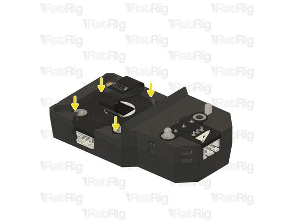
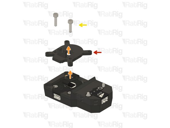
Oozeguard assembly
-
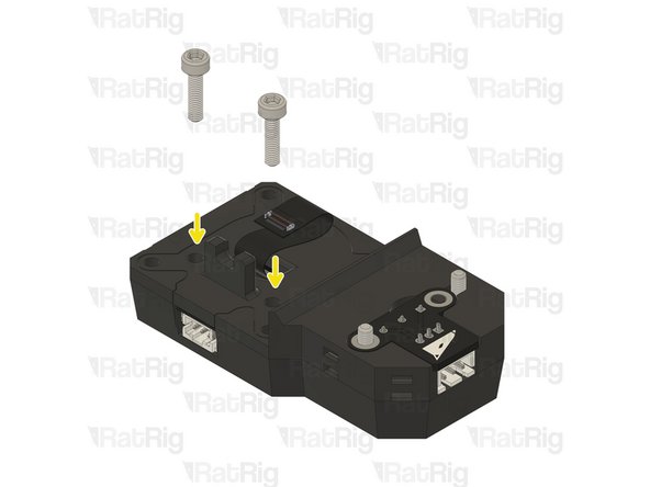
2x M3x8 Set screw
-
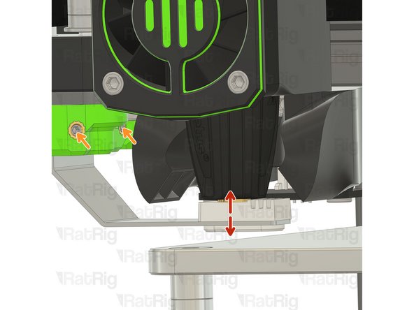
Loosely tighten the set screws to hold the Oozeguard in place. Its height will be adjusted in the next step.
-
-
-
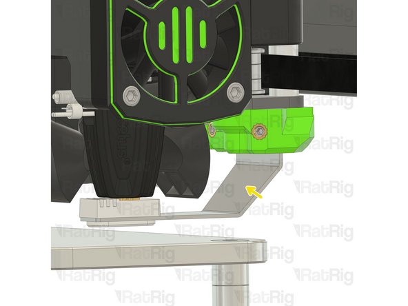
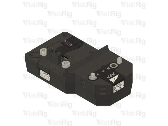
Position the toolhead above the Oozeguard silicone pad and adjust it up or down until the nozzle is firmly covered by the pad.
-
Tighten the set screws
-
Repeat Step 2 and 3 for the T1 oozeguard
-
-
-
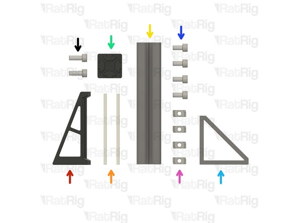
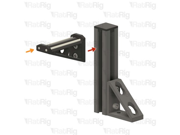
1x vc4_spoolholder_arm
-
2x 87mm PTFE Tube
-
1x T-Slot 3030 extrusion- 150mm
-
1x 3030_end_cap
-
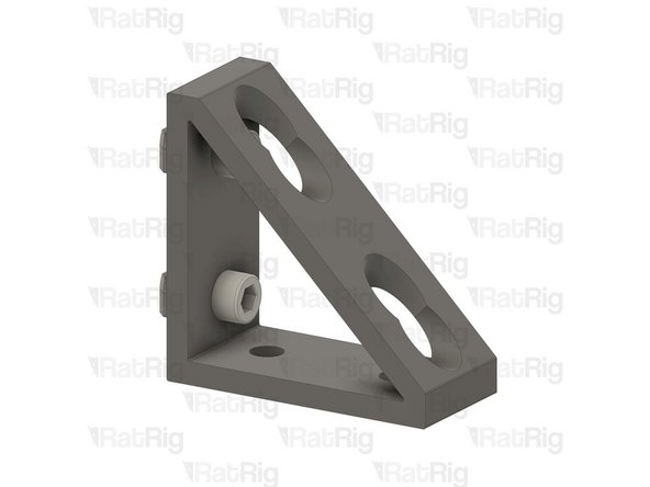
1x Extruded 90° Corner- 6030 Tall
-
4x M6x12 Cap Head Screw
-
4x 3030 Drop-in T-Nut - M6
-
2x M6x16 Cap Head Screw
-
-
-
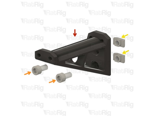
vc4_spoolholder_arm
-
2x M6x12 Cap Head Screw
-
2x 3030 Drop-in T-Nut - M6
-
Install the M6x12 Cap head screws into the spool holder as shown.
-
Loosely thread a 3030 T-Nuts onto the M6x12 screws. Do not tighten it at this point.
-
-
-
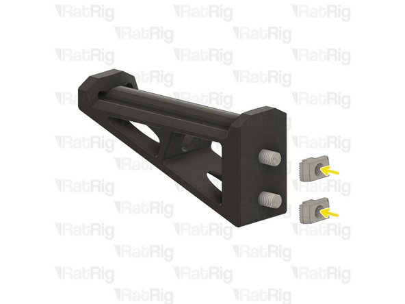
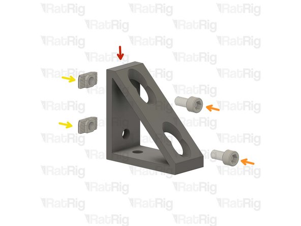
1x Extruded 90° Corner- 6030 Tall
-
2x M6x12 Cap Head Screw
-
2x 3030 Drop-in T-Nut - M6
-
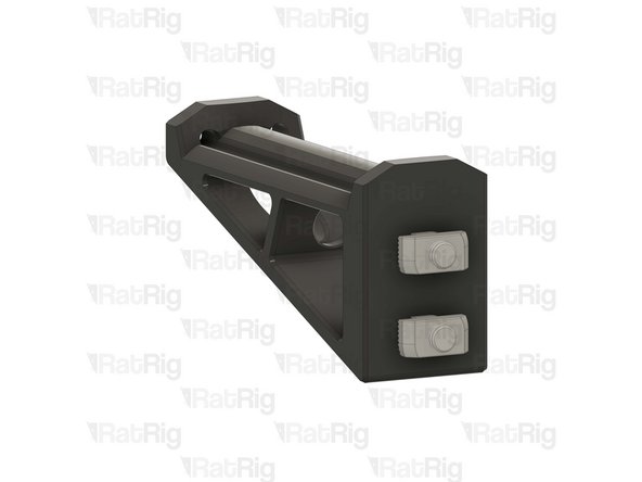
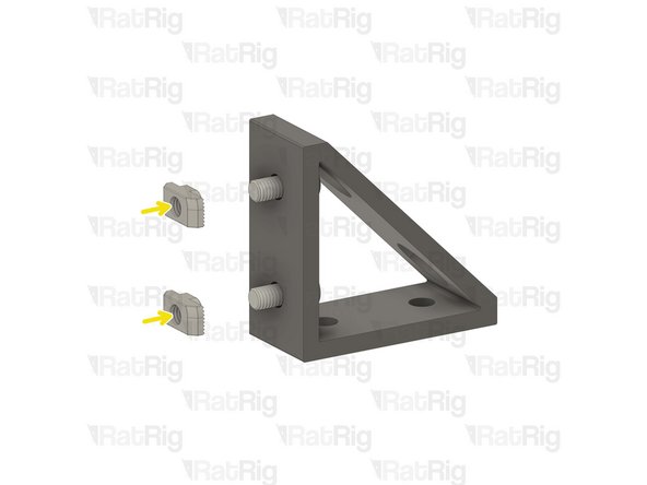
Install the M6 cap head screws into the corner bracket as shown.
-
Loosely thread a 3030 T-Nut onto each of the M6x12 screws. Do not tighten it at this point.
-
-
-
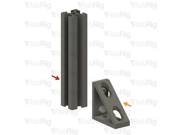
T-Slot 3030 extrusion- 150mm
-
Corner bracket assembly from the previous Step
-
Attach the corner bracket assembly to the aluminium extrusion, aligning the flat edges together.
-
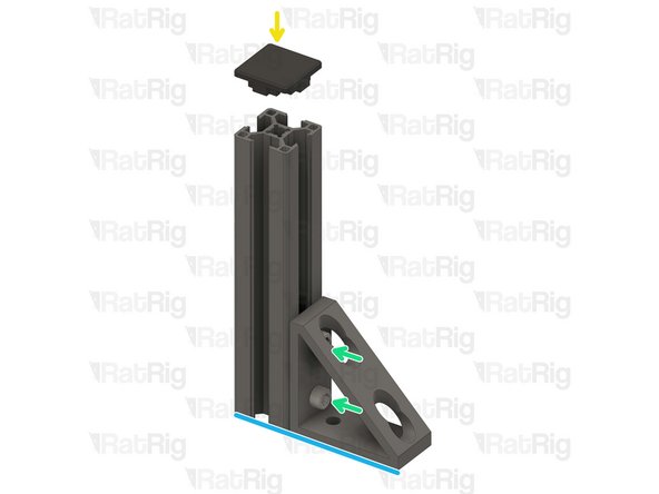
3030_end_cap
-
Place the printed cap on the other end.
-
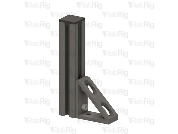
Tighten the M6x12 screws to secure the corner bracket to the extrusion.
-
Ensure the extrusion is flush with the corner bracket
-
-
-
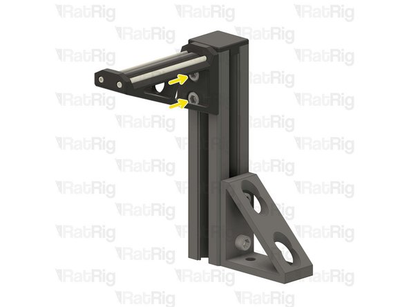
Spool holder printed part
-
T-Slot 3030 extrusion- 150mm
-
Attach the spool holder printed part to the aluminium extrusion as shown, aligning the top edges.
-
Tighten the M6x12 screw to secure the spool holder to the extrusion.
-
Take care not to over tighten the screws as you can damage the printed parts.
-
-
-
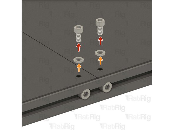
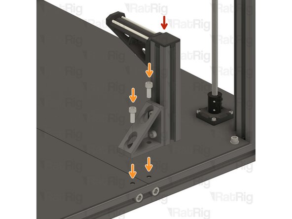
The spool holder can be mounted on either side of the machine, this guide will instruct you to install it on the left side of the machine for single-head configuration.
-
2x M6x12 Cap Head Screw
-
2x M6 Washer
-
Remove the shown M6x12 screws and their corresponding washers in order to allow for the spool holder arm to be installed.
-
Avoid moving the machine around or bumping into it, to prevent the t-nuts from moving.
-
The second spool holder is assembled! almost ready to print
-
-
-
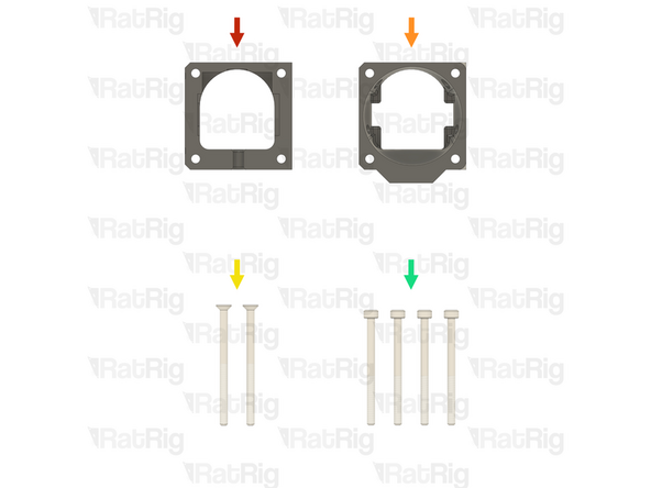
1x Prepared VAOC diffusor assembly from step 61 of the Preparations guide
-
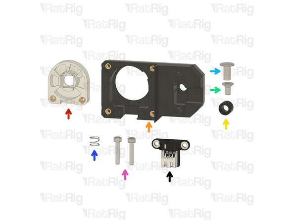
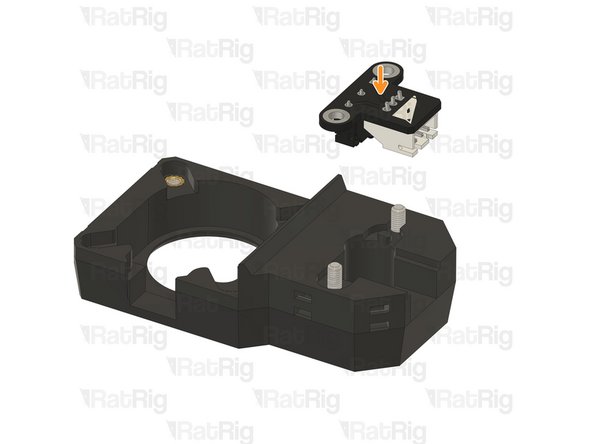
1x Prepared VAOC body assembly from step 60 of the Preparations guide
-
1x POM Spacer - OD9xID5.1x6mm for VAOC (SKU: HW4142GC)
-
1x M4x8 Countersink Screw (SKU: HW4083SC)
-
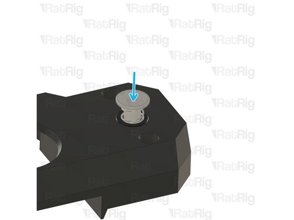
1x Custom CNC machined chicago bolt actuator button (SKU: HW4143GC)
-
1x Spring - Stainless Steel (SKU: HW4093GC)
-
2x M3x16 Cap Head Screw (SKU: HW1507SC)
-
1x Rat Rig VAOC Endstop v1.0 (SKU: HW4084MK)
-
-
-
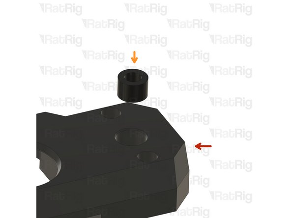
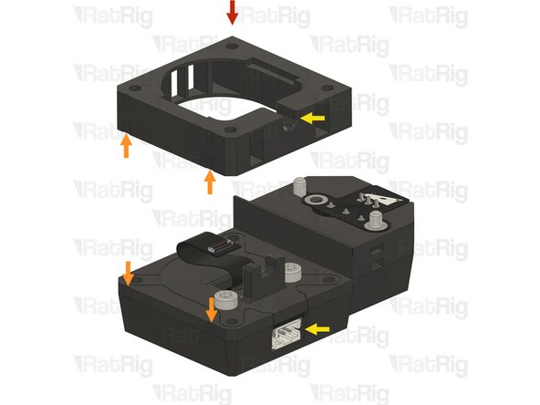
Prepared VAOC body assembly
-
POM Spacer - OD9xID5.1x6mm for VAOC
-
Insert the spacer into the VAOC body assembly as shown
-
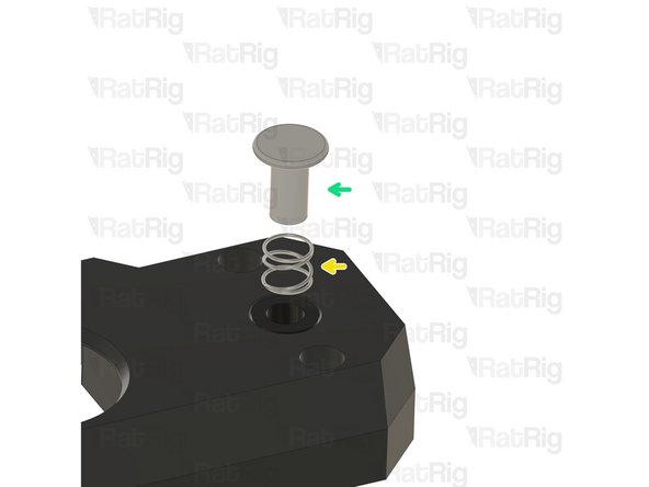
Spring - Stainless Steel
-
Custom CNC machined chicago bolt actuator button
-
Slip the spring over the shaft of the actuator button and then insert the shaft of the actuator button into the POM Spacer as shown
-
Keep pressure on the actuator button until the following step is completed
-
-
-
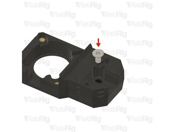
M4x8 Countersink Screw
-
Fasten the M4x8 Countersink Screw into the threads inside the actuator button shaft as shown
-
Make sure the M4x8 Countersink Screw is fully tightened
-
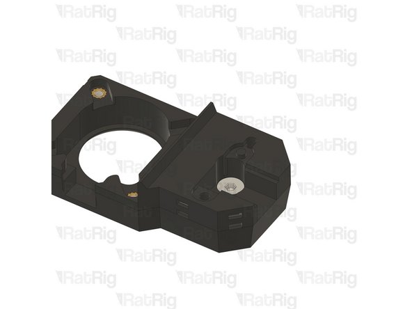
Test the movement of the actuator button. It should freely move up and down without binding
-
-
-
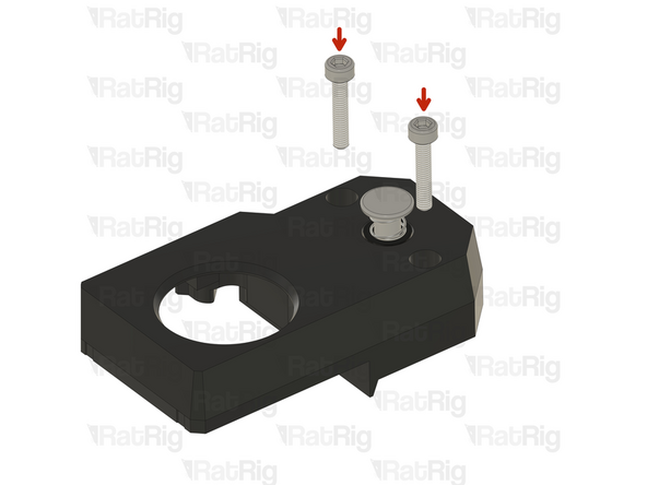
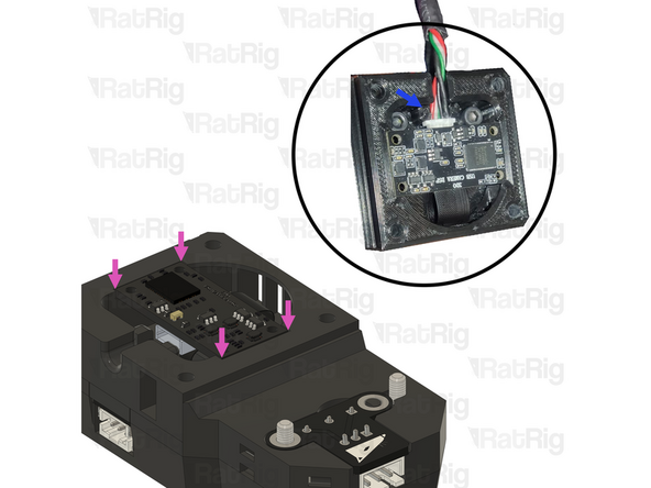
2x M3x16 Cap Head Screw
-
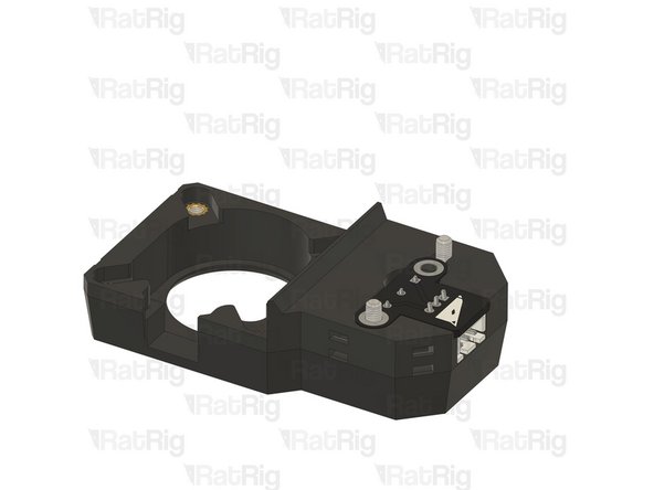
Insert the M3x16 Cap Head Screws into the marked holes
-
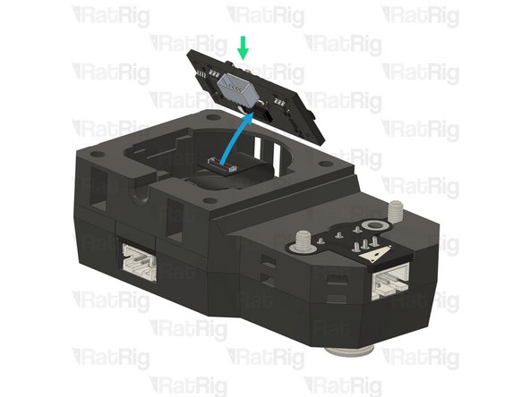
Rat Rig VAOC Endstop v1.0
-
Insert the Rat Rig VAOC Endstop into the VAOC module as shown
-
Make sure to avoid the VAOC Endstop or M3x16 Cap Head Screws falling out during the following steps
-
-
-
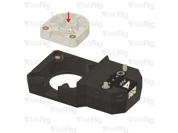
Prepared VAOC diffusor assembly
-
Insert the VAOC diffusor into the VAOC body as shown
-
-
-
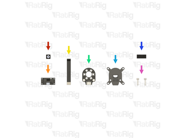
Rat Rig VAOC Camera Module (With 50mm FPC) (SKU: HW3992EC)
-
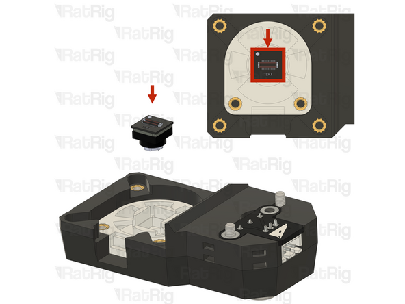
1x Rat Rig VAOC Camera
-
1x Rat Rig VAOC Camera DSP Board
-
1x 50mm FPC
-
1x Rat Rig VAOC LED Module (SKU: HW3998EC)
-
1x vc4_vaoc_midframe Printed Part (SKU: PP000359)
-
20mm of Foam Strip - 1mm x 8mm - Adhesive 3M - EVA material (SKU: HW2943GC)
-
2x M3x12 Cap Head Screw (SKU: HW1292SC)
-
-
-
Insert the Rat Rig VAOC Camera into the diffusor, using the white mark to orient it correctly
-
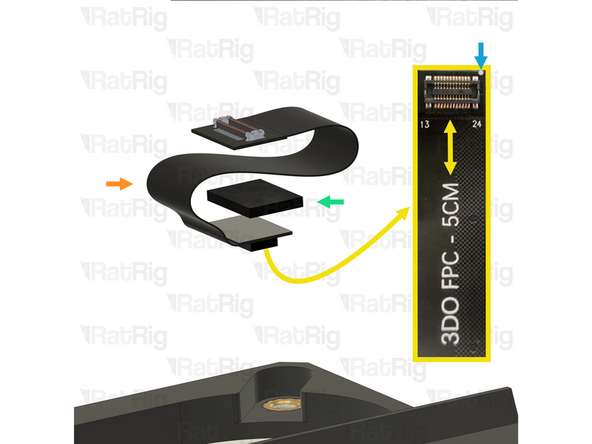
50mm FPC
-
The camera end of the FPC is where the text "3DO FPC - 5cm" ends
-
Foam Strip - 1mm x 8mm - Adhesive 3M - EVA material
-
Cut the foam to the size of the back of the FPC connector and apply it only to the back of the camera end
-
Use the white mark on the FPC to correctly orient it up with the VAOC Camera
-
Connect the FPC to the VAOC Camera as shown. Make sure the orientation is correct
-
-
-
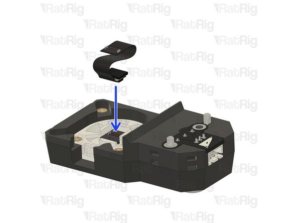
Rat Rig VAOC LED module
-
Pass the opposite end of the FPC through the hole in the centre of the VAOC LED module, ensuring it remains connected to the VAOC Camera
-
Insert the VAOC LED Module into the VAOC assembly as shown
-
It is possible that the Rat Rig VAOC LED Module PCB has small imperfections from manufacturing which could cause interferences when installing
-
If the Rat Rig VAOC LED Module does not fit correctly, you can use some sandpaper to smooth down any remaining imperfections
-
If it is necessary to smooth the PCB edges, do it in a well-ventilated area and wear a mask. PCB dust is hazardous to your health
-
-
-
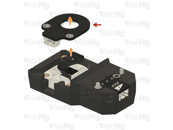
vc4_vaoc_midframe
-
Pass the end of the FPC through the hole in the centre of the vc4_vaoc_midframe printed part, ensuring it remains connected to the VAOC Camera
-
M3x12 Cap Head Screws
-
Insert the M3x12 Cap Head Screws through the midframe, VAOC LED Module and tighten them into the VAOC diffusor
-
Take care not to overtighten the screws as you can damage the printed parts
-
-
-
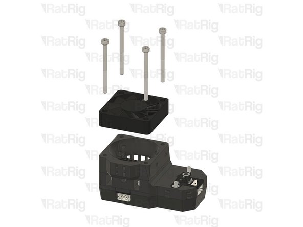
1x vc4_vaoc_vent Printed Part (SKU: PP000356)
-
1x vc4_vaoc_duct Printed Part (SKU: PP000357)
-
2x M3x45 Countersink Screw (SKU: HW3497SC)
-
4x M3x40 Cap Head Screw (SKU: HW1869SC)
-
-
-
The VAOC wiring should have been pre-run in step 60 through step 63 of the Wiring Guide. The remaining VAOC assembly steps will need to be performed on the V-Core 4.0 assembly
-
vc4_vaoc_vent
-
Align the small markers on the printed parts to ensure the correct orientation of the assembly
-
Make sure the marked cable exit is facing upwards and is on the same side as the VAOC LED Module connector
-
Rat Rig VAOC Camera DSP Board
-
Connect the FPC to the VAOC Camera DSP Board as shown
-
Connect the Rat Rig VAOC Camera DSP Board to the USB-A to Rat Rig VAOC Camera cable which was installed in step 61 of the Wiring Guide
-
Fit the Rat Rig VAOC Camera DSP Board into the VAOC assembly as shown. The VAOC midframe will secure the Camera DSP Board USB connector preventing it from disconnecting
-
-
-
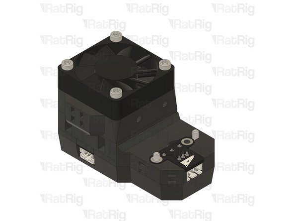
vc4_vaoc_duct
-
Fan - 40mm Axial Brushless 24V DC - 1500mm Cable previously installed in step 63 of the Wiring Guide
-
Orient the fan as shown so that the label on the fan faces into the VAOC Module assembly and that the fan cable exits the on the same side as the VAOC LED Module connector
-
4x M3x40 Cap Head screw
-
Align the small markers on the printed parts to ensure the correct orientation of the assembly
-
Make sure the marked cable management is on the same side as the VAOC LED Module connector
-
-
-
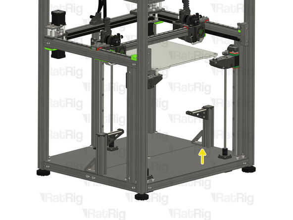
It is recommended to temporarily lift the bed assembly off of the arms and set it on the base of the V-Core 4.0 to allow better access to install the VAOC Module
-
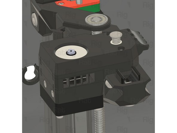
VAOC Module assembly from the previous step
-
Align the two screws with the heat inserts on the top of the rear Z-axis arm
-
Fully tighten both M3x16 Cap Head Screws to secure the VAOC Module to the rear bed arm
-
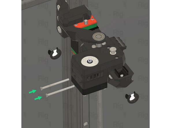
2x M3x45 Countersink screw
-
Insert the both M3x45 Countersink Screws through the holes in the side of the VAOC Module and tighten them into the rear Z-axis arm
-
Take care not to overtighten the screws as you can damage the printed parts
-
-
-
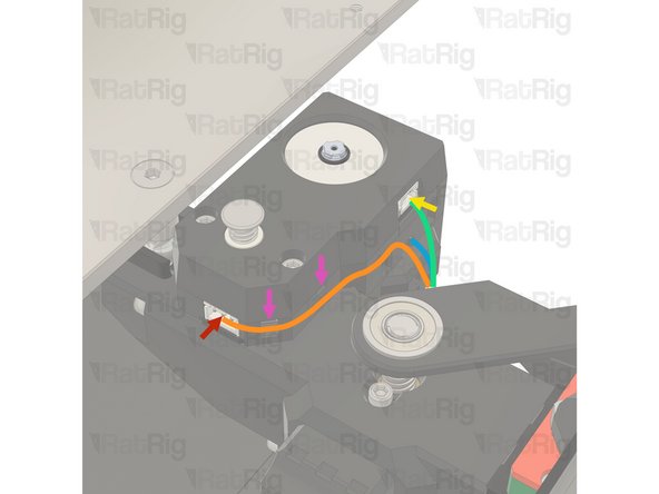
Connect the VAOC Endstop cable which was pre-installed in step 61 of the Wiring Guide to the VAOC Endstop
-
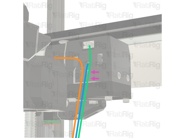
Route the VAOC endstop cable as shown
-
Connect the VAOC LED cable which was pre-wired in step 62 of the Wiring Guide to the VAOC LED Module
-
Route the VAOC LED Module cable as shown
-
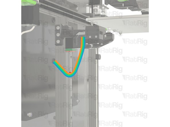
Route the VAOC Camera Module cable as shown
-
Use zip ties to secure the wiring to the assembly to ensure proper stress relief
-