-
-
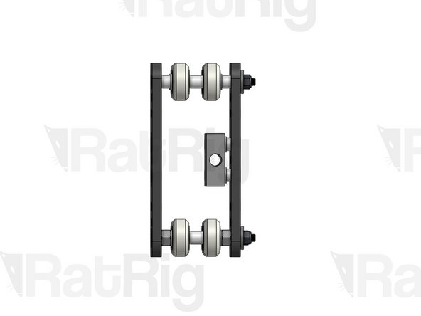
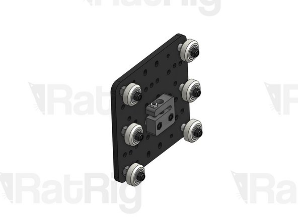
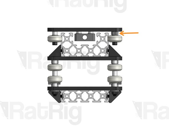
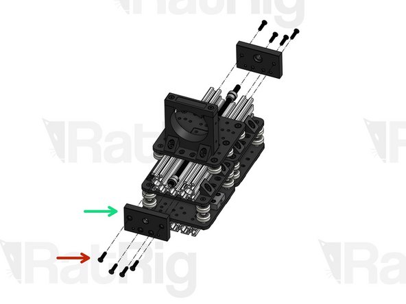
Tighten down the Nut Block on the left, but leave the one on the right slightly loose. You will need some play in a moment.
-
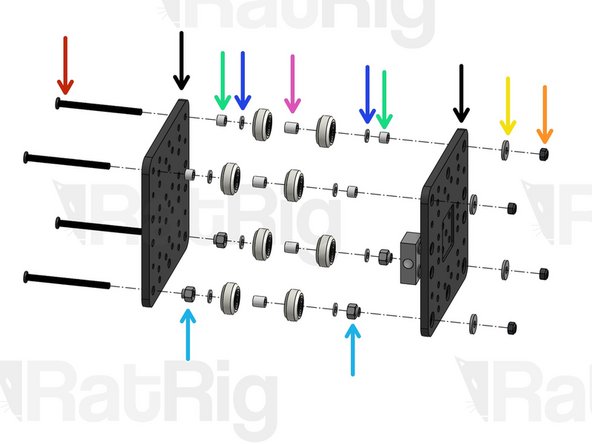
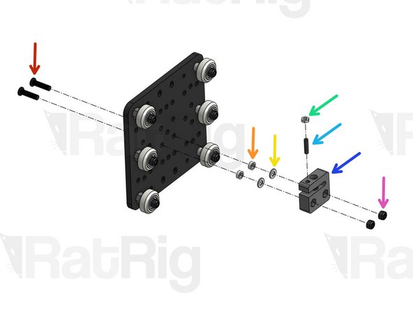
Low Profile Screw M5x20mm
-
C-Beam Gantry Plate XL
-
Spacer 3mm
-
Precision Shim 10x5x1mm
-
Nut Block
-
Hex Locking Nut M5
-
-
-
Lead Screw
-
Fasten a lead screw (at this point it doesn't matter which one) through both nut blocks.
-
Tighten down the loose Nut Block on the right, while applying lateral pressure on it at the same time (towards the other Nut Block). Once both blocks are tightened, your lead screw should have zero backlash.
-
To check if there's backlash, grab the plate with one hand and the lead screw with the other. Without turning the lead screw, try to move it back and forth. There should be no wiggle room for the lead screw to move at all. If there is, loosen one of the nut blocks and try adjusting its position again.
-
Once all backlash is removed, unfasten your lead screw, you will add it to the build later on.
-
-
-
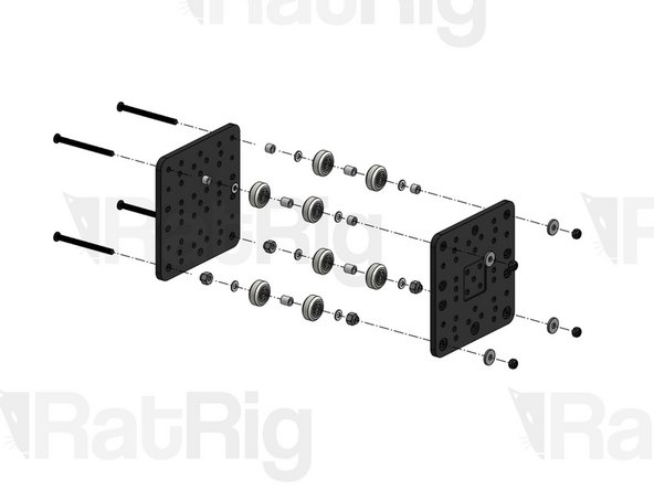
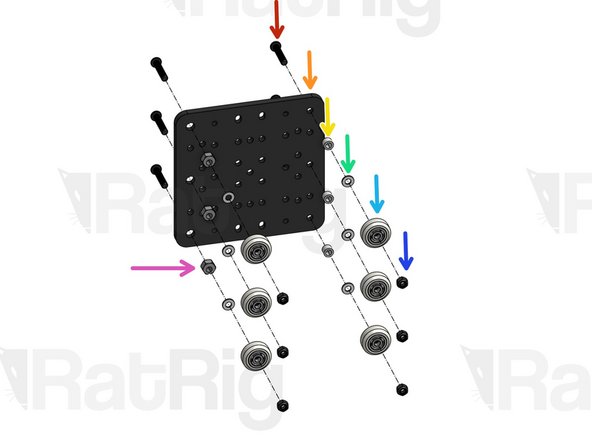
Low Profile Screw M5x65mm
-
C-Beam Gantry Plate XL
-
Aluminium Spacer 6mm
-
Eccentric Spacer
-
Precision Shim 10x5x1mm
-
Aluminium Spacer 9mm
-
Slot Washer 15x5x2mm
-
Hex Locking Nut M5
-
-
-
Assemble a second X Carriage just like the first one, but without Nut blocks (you can follow step 3 with a new pair of C-Beam Gantry Plate XL)
-
-
-
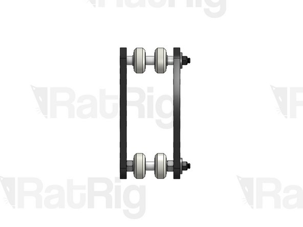
Repeat this step for both X carriages
-
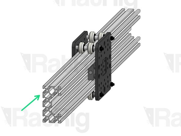
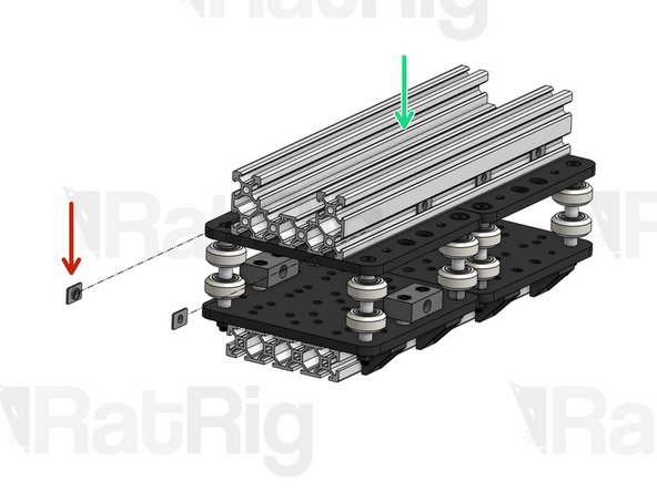
Insert a C-Beam profile (doesn't matter which one at this point) through your assembly.
-
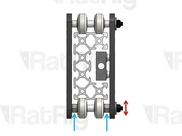
Eccentric Spacers have an off-center through-hole. Because of this, when you rotate them, your entire wheel axis moves laterally. This gives you the adjustment margin you will need to make sure your wheels are grabbing the profile with the correct amount of force.
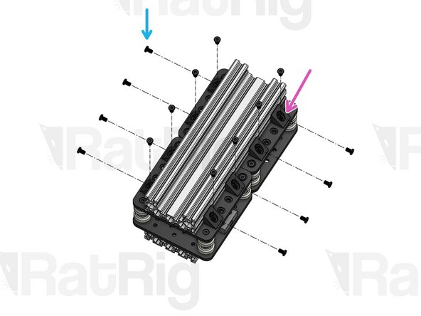
-
Use a spanner to subtly adjust the position of each eccentric spacer until every wheel is in contact with the profile. You want to find a sweet spot where your carriage is not wobbly and the motion is perfectly smooth, but where there isn't excessive force pressing the wheels against the rail, as this will increase wear on the wheels.
-
-
-
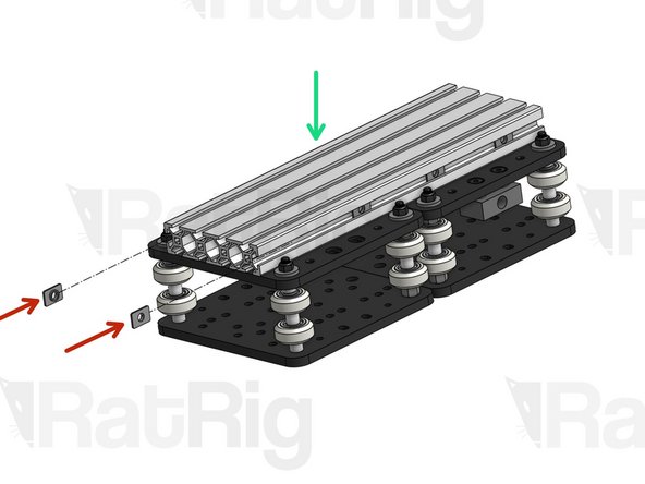
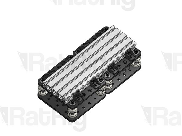
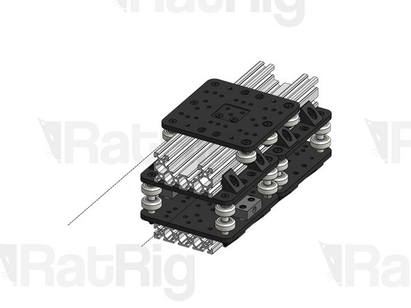
Join the 2 X carriages together, noting the position of the Nut blocks in the picture.
-
Place the Z Carriage 2080 profile (250mm) on top of the 2 carriages. The ends of the profile should be flush with the ends of the carriages.
-
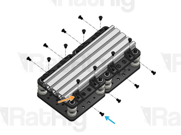
Insert 4 T-Nuts M5 on each lateral slot of the 2080. Note the orientation of the T-Nuts (flat side facing outwards)
-
Cast Corner (x8)
-
Low Profile Screw M5x8mm (16 in total). Use 2 per Cast Corner. One should fasten into the carriage thread, the other one into the T-Nut previously inserted.
-
-
-
Low Profile Screw M5x27mm
-
C-Beam Gantry Plate XL
-
Spacer 6mm
-
Precision Shim 10x5x1mm
-
Xtreme V-Wheel
-
Hex Locking Nut M5
-
Eccentric Spacer
-
-
-
Low Profile Screw M5x20mm
-
Spacer 3mm
-
Precision Shim 10x5x1mm
-
Hex Nut M5
-
Set Screw M5x16mm
-
You will tighten this later once you're ready to calibrate your Anti-backlash nut. For now, tighten only until you feel the slightest resistance.
-
Anti-backlash Nut Block
-
Hex Locking Nut M5
-
-
-
Place the Z C-Beam profile on the opposite side of the 2 carriages. The ends of the profile should be flush with the ends of the carriages.
-
TIP: you can actually move the C-Beam further up or down as needed, depending on what you're trying to mill and what height range is required.
-
Insert 4 T-Nuts M5 on each lateral slot of the C-Beam. Note the orientation of the T-Nuts (flat side facing outwards)
-
Angle Corner (x8)
-
Low Profile Screw M5x8mm (16 in total). Use 2 per Angle Corner. One should fasten into the carriage thread, the other one into the T-Nut previously inserted.
-
-
-
Slide the carriage on the C-Beam slots.
-
Use a spanner to subtly adjust the position of each eccentric spacer until every wheel is in contact with the profile. You want to find a sweet spot where your carriage is not wobbly and the motion is perfectly smooth, but where there isn't excessive force pressing the wheels against the rail, as this will increase wear on the wheels.
-
-
-
Remove the Z Carriage from the C-Beam
-
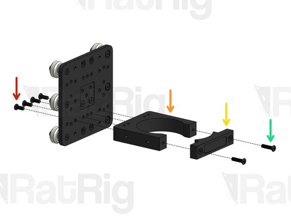
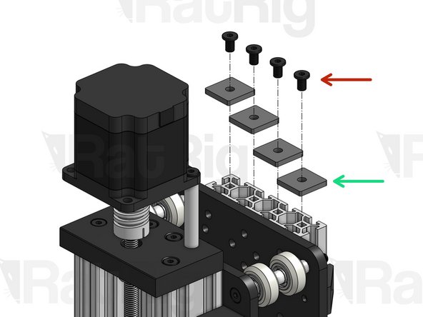
Low Profile Screw M5x12mm (x4)
-
Spindle Mount Bottom Piece
-
Spindle Mount Top Piece
-
Low Profile Screw M5x20mm (x2)
-
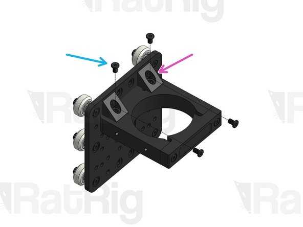
Angle Corners
-
Low Profile Screw M5x8mm (x4)
-
-
-
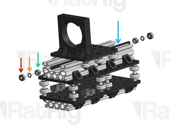
Insert the Z Carriage on the C-Beam. Note the orientation of the Spindle mount and of the Nut Blocks on the image.
-
Z Lead Screw. Thread it through the Anti-backlash Nut Block.
-
Hold the Z carriage firmly with one hand and try to pull/push the lead screw, without turning it. If you find any wiggle room, tighten the Set Screw on the Anti-backlash Nut Block until all play disappears. Then, tighten the Hex nut. This nut may require tuning from time to time. Do not overtighten, as this may overconstrain the lead screw.
-
Insert the parts below on each end of the lead screw for now. You will lock them in place in a moment.
-
688ZZ Ball Bearing (x2)
-
Precision Shim 12x8x1mm (x2)
-
Lock Collar 8mm (x2)
-
-
-
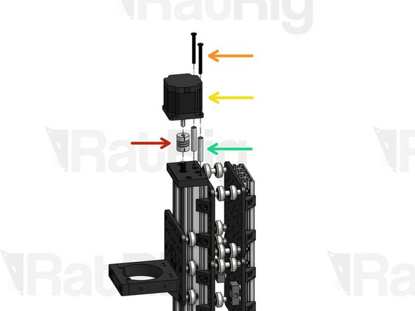
Low Profile Screw M5x50mm
-
Nema 23 Motor
-
The wire on the motor should be towards the back of the X-Carriage-Assembly.
-
Aluminium Spacer 40mm
-
Flexible Coupling - 1/4" x 8mm
-
Attach the 1/4'' end of the flexible coupling to the motor shaft and the 8mm end to the lead screw. The motor shaft is shaped like a "D". Align the flat surface of the D with the Set Screw on the Flexible coupling. Tighten the clamping screws and then the set screws.
-
-
-
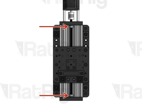
Press the Lock Collars against the inner face of each C-Beam End Mount and tighten their Set Screw, to lock them in position.
-