
-
-
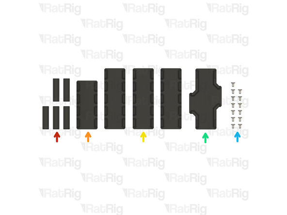
vc4_enclosure_alu_base_V1
-
vc4_enclosure_alu_top_V1
-
vc4_enclosure_alu_left_V1
-
vc4_enclosure_alu_bottom_V1
-
vc4_enclosure_alu_right_V1
-
4x vc4_Enclosure_alum_corner_V1
-
20x M3x6 Countersink Screw
-
-
-
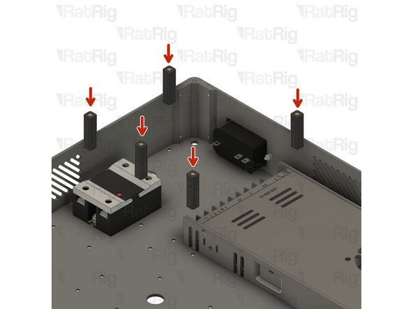
vc4_enclosure_alu_base_V1
-
vc4_Enclosure_alum_corner_V1
-
M3x6 Countersink Screw
-
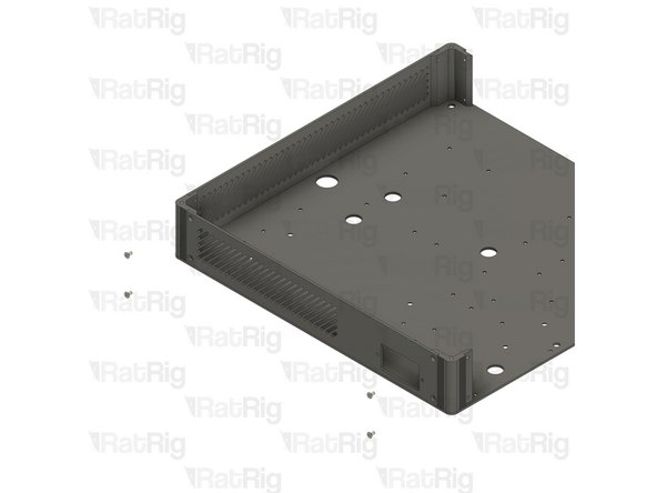
Assemble the components as shown, and ensure the vc4_enclosure_alu_base_V1 is correctly oriented and the countersunk screw is inserted into the countersink groove.
-
Repeat the previous Steps and assemble the remaining corners.
-
-
-
vc4_enclosure_alu_top_V1
-
4x M3x6 Countersink Screw
-
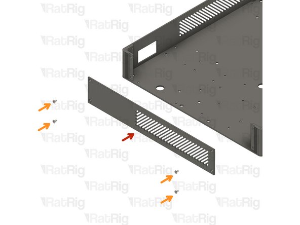
Assemble the enclosure components as shown, making sure the panels are correctly oriented. The countersink screw holes should face outwards from the enclosure, and the countersink screws should be flush with the surface when fully tightened.
-
-
-
vc4_enclosure_alu_left_V1
-
4x M3x6 Countersink Screw
-
Assemble the enclosure components as shown, making sure the panels are correctly oriented. The countersink screw holes should face outwards from the enclosure, and the countersink screws should be flush with the surface when fully tightened.
-
-
-
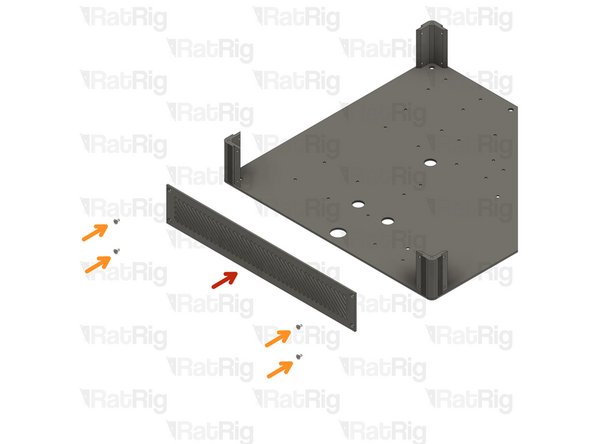
vc4_enclosure_alu_bottom_V1
-
4x M3x6 Countersink Screw
-
Assemble the enclosure components as shown, making sure the panels are correctly oriented. The countersink screw holes should face outwards from the enclosure, and the countersink screws should be flush with the surface when fully tightened.
-
-
-
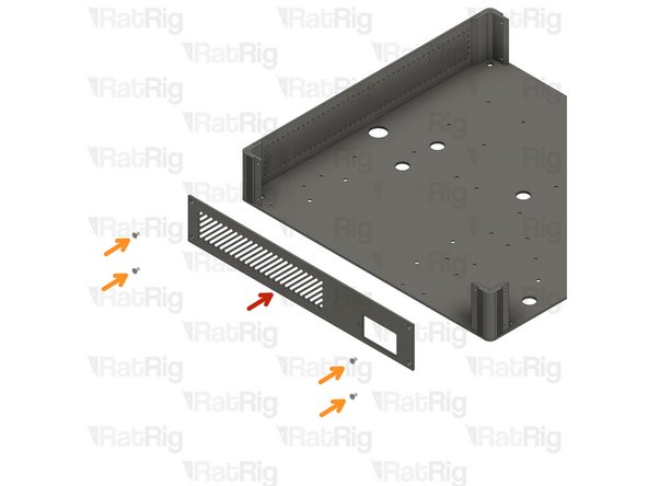
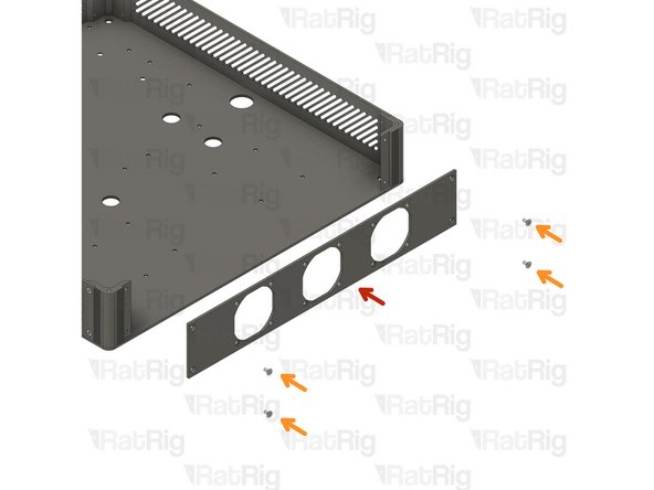
vc4_enclosure_alu_right_V1
-
4x M3x6 Countersink Screw
-
Assemble the enclosure components as shown, making sure the panels are correctly oriented. The countersink screw holes should face outwards from the enclosure, and the countersink screws should be flush with the surface when fully tightened.
-
-
-
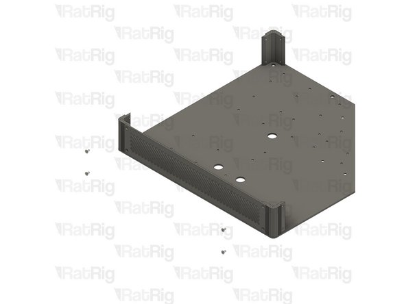
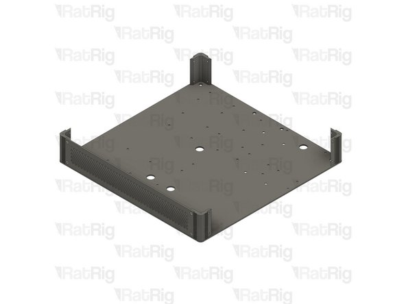
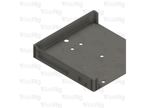
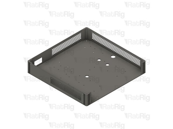
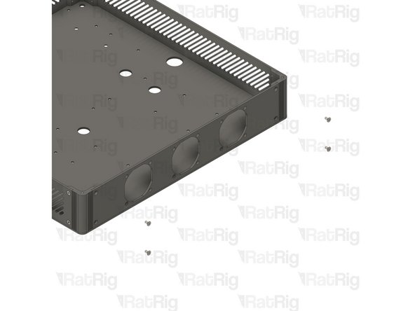
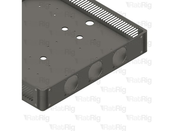
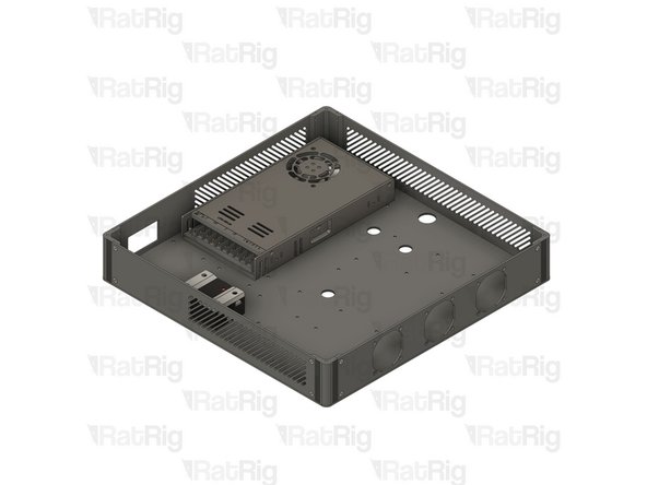
Double-check if all panels are correctly oriented and the assembly looks exactly like the picture.
-
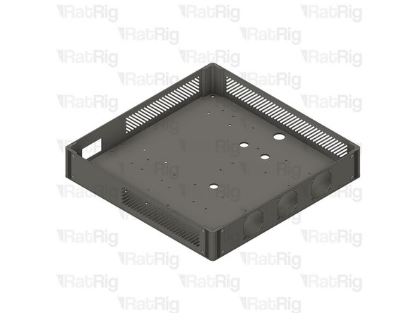
Skip to Step 17, as the next steps are dedicated to the electronics enclosure V2.
-
-
-
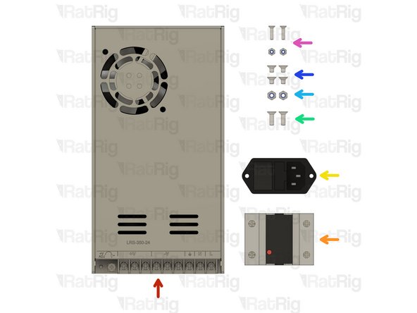
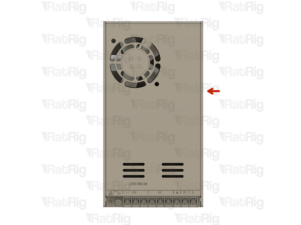
Power Supply Weho - 250Watt 24V - Fanless
-
SSR 40A480VAC Solid State Relay
-
IEC Socket - Switchable & Fused (Plain switch & 10A fuse)
-
If you received an IEC connector that resembles the one shown in the picture, please do not install it. The correct installation steps will be provided later in the guide.
-
2x M4x12 Countersink Screw
-
2x M4 Nylon Locking Nut
-
4x M4x6 Countersink Screw
-
2x M3 Nylon Locking Nut + 2x M3x12 Countersink Screw
-
-
-
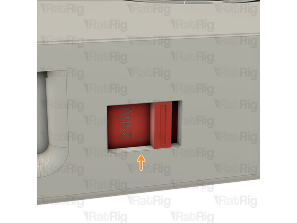
On the right side of the power supply there is a switch.
-
This switch needs to be set to the mains voltage in your country. Either 115V (most common in the USA / Canada), or 230V.
-
Setting this to the incorrect input voltage may destroy the power supply and anything connected to it.
-
-
-
Electronics Enclosure assembly
-
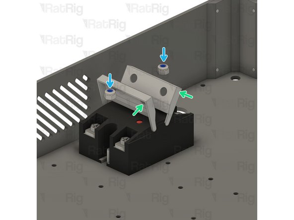
SSR 40A480VAC Solid State Relay
-
2x M4x12 Countersink screws
-
Gently open the SSR Relay tabs to access the mounting holes.
-
2x M4 Nylon Locking Nut
-
Tighten the screws to secure the SSR Relay to the electronics enclosure
-
-
-
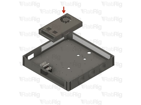
Power Supply Weho - 250Watt 24V - Fanless
-
4x M4x6 Countersink Screw
-
Mount the power supply as shown, and tighten the screws to secure it to the electronics enclosure.
-
-
-
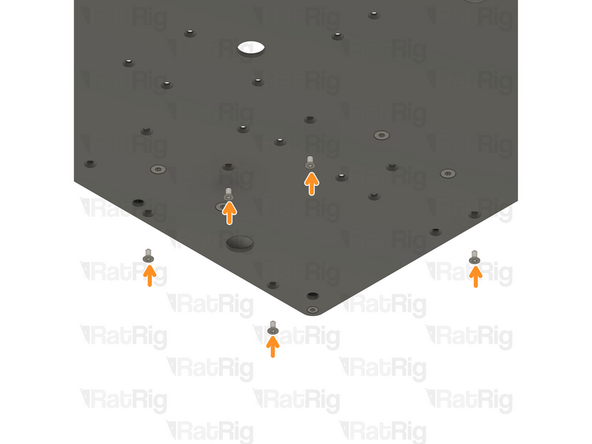
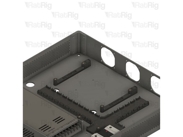
5x vc4_ac_cover_support assembly
-
vc4_cable_guide_4 assembly
-
3x vc4_cable_guide_5 assembly
-
vc4_cable_guide_cross
-
13x M3x6 Countersink Screws
-
-
-
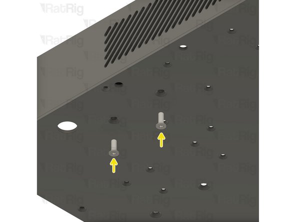
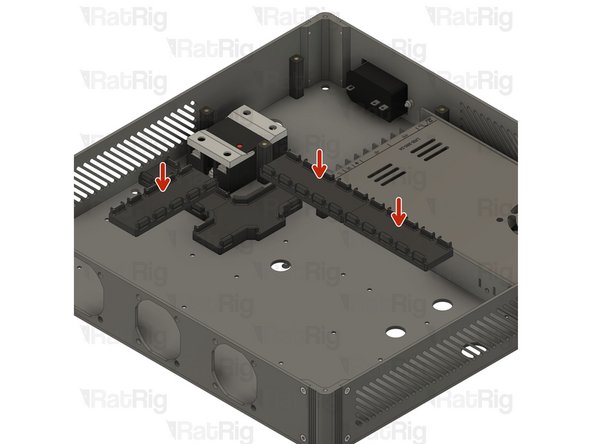
vc4_ac_cover_support assembly
-
5x M3x6 Countersink Screws
-
Insert the M3x6 Countersink Screws from the bottom, into the designated holes, and secure the vc4_ac_support assemblies to the enclosure.
-
Take care not to over-tighten the screws as you can damage the printed parts
-
-
-
vc4_cable_guide_cross
-
vc4_cable_guide_4 assembly
-
M3x6 Countersink Screws
-
Insert the M3x6 Countersink Screws from the bottom, into the designated holes, and secure the assemblies to the enclosure.
-
Take care not to over-tighten the screws as you can damage the printed parts
-
-
-
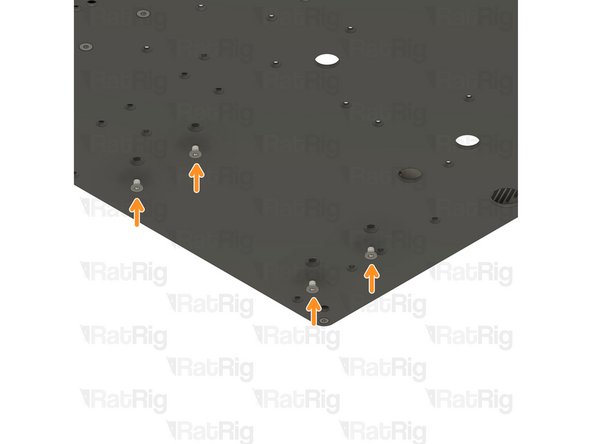
3x vc4_cable_guide_5 assembly
-
6x M3x6 Countersink Screws
-
Insert the M3x6 Countersink Screws from the bottom, into the designated holes, and secure the vc4_ac_support assemblies to the enclosure.
-
Take care not to over-tighten the screws as you can damage the printed parts
-
-
-
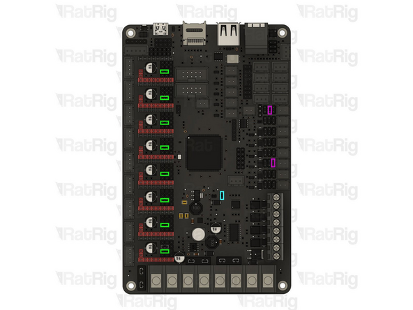
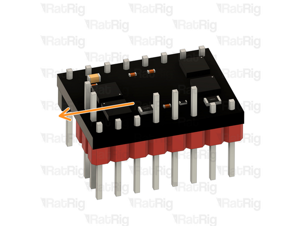
BIGTREETECH Octopus V1.1
-
Remove all the jumpers on the board before starting. Insert the jumpers onto the highlighted pins.
-
UART mode - placing these jumpers will allow for tuning and controlling options on the printer interface.
-
USB-C Power option - with this jumper the board can be powered via USB-C. This will allow you to compile and download the firmware directly to the motherboard using DFU mode, ideal for testing the board.
-
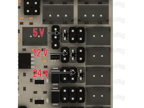
Voltage Selection - Each fan output can be set to one of three different voltages (5V, 12V or 24V) depending on the jumper positions. The third image exemplifies where the pins must be placed to achieve different voltages.
-
The voltage selections used in the guide are for the electronics kit provided by Rat Rig. If using different fans, ensure the voltages are set correctly to avoid damage to components.
-
-
-
BIGTREETECH Octopus V1.1 with the jumpers from the previous Step
-
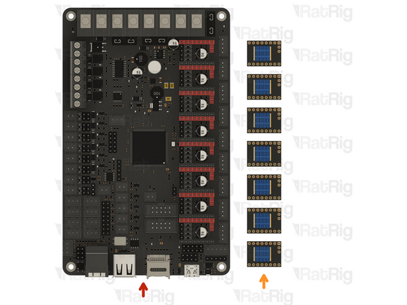
5x TMC2209 Stepper Driver for CoreXY
-
7x TMC2209 Stepper Driver for Hybrid
-
Orient the TMC2209 Stepper Drivers with the two upper pins to the outside of the board.
-
Make sure the drivers are inserted all the way to ensure a reliable connection.
-
Insert the TMC2209 drivers slowly while checking pin alignment to avoid damaging the components.
-
These two drivers are only used on the Hybrid and IDEX configurations
-
-
-
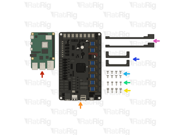
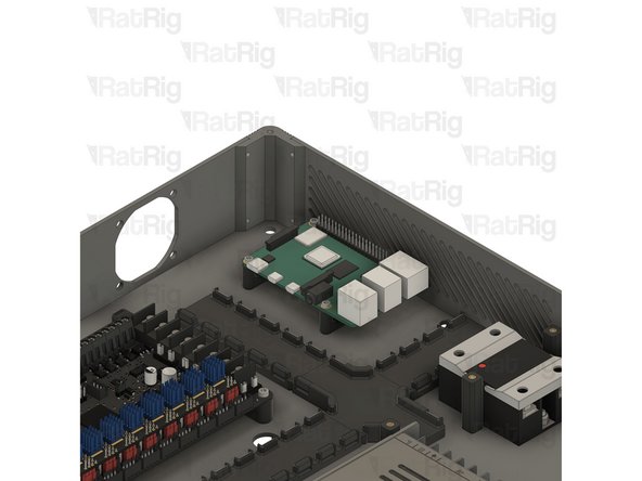
Raspberry Pi 4B
-
Octopus V1.1 assembly
-
4x M3x8 Cap Head Screw
-
4x M2.5x6 Cap Head Screws
-
8x M3x6 Countersink Screw
-
2x vc4_adapter_rpi assembly
-
vc4_adapter_octopus assembly
-
-
-
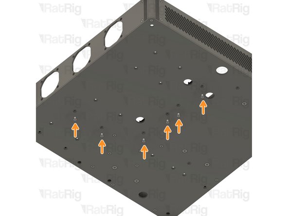
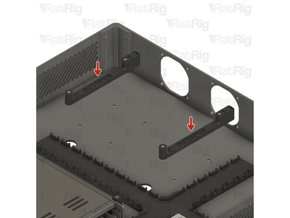
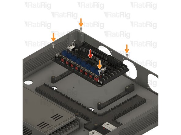
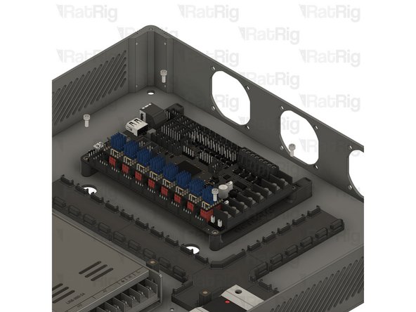
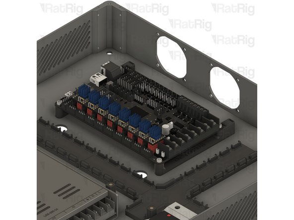
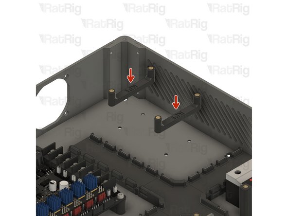
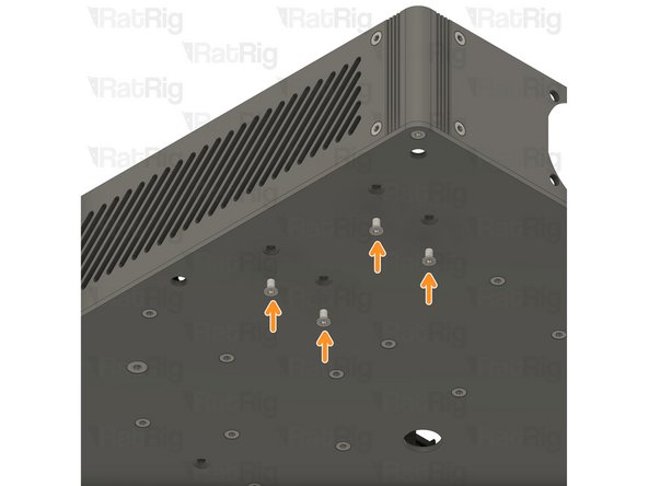
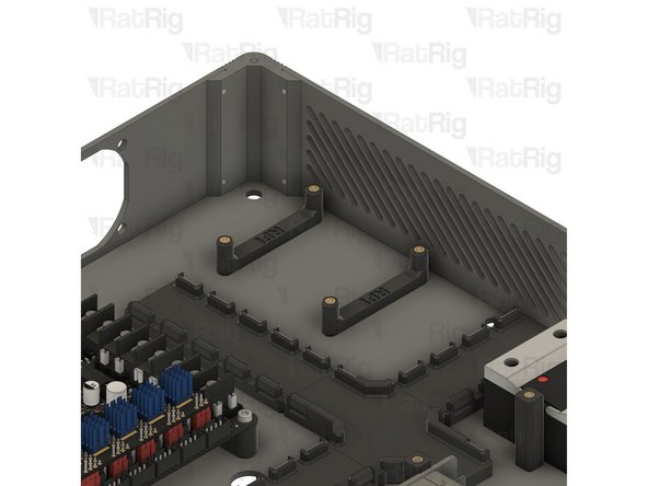
Install the Octopus board mounts
-
M3x6 Countersink Screw
-
Insert the M3x6 Countersink Screws from the bottom, into the designated holes, and secure the assemblies to the enclosure.
-
Take care not to over-tighten the screws as you can damage the printed parts
-
-
-
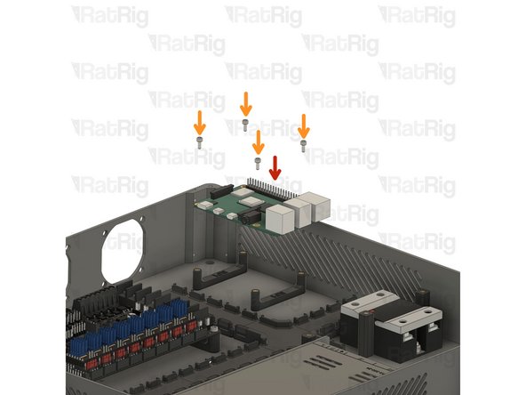
BigTreeTech Octopus V1.1 Motherboard
-
4x M3x8 Cap Head Screw
-
Inster the M3x8 Cap Head Screws through the Octopus V1.1 Board and tighten it to the vc4_adapter_octopus assembly
-
Take care not to over-tighten the screws as you can damage the board and the printed parts
-
-
-
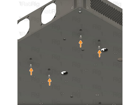
2x vc4_adapter_rpi assembly
-
M3x6 Countersink Screw
-
Insert the M3x6 Countersink Screws from the bottom, into the designated holes, and secure the assemblies to the enclosure.
-
Take care not to over-tighten the screws as you can damage the printed parts
-
-
-
Raspberry Pi 4B
-
M2.5x6 Cap Head Screws
-
Insert the M2.5x6 Cap Head Screws through the Raspberry Pi Board and tighten it to the vc4_adapter_rpi_assembly
-
Take care not to over-tighten the screws as you can damage the printed parts
-
-
-
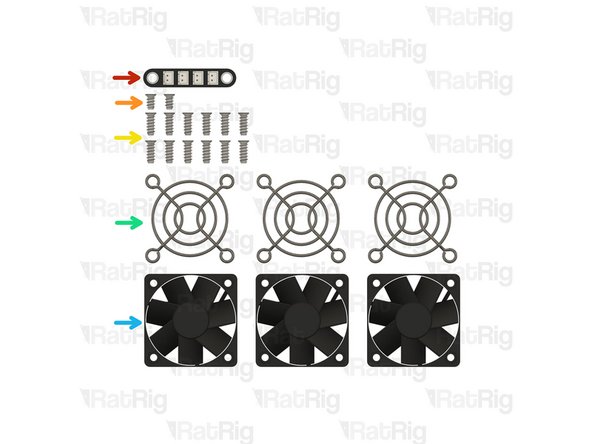
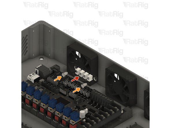
Rat Rig 3-to-1 XH Splitter - 2 Pin - V1
-
2x Self Tapping Screw - Fan - 8mm
-
12x Self Tapping Screw - Fan - 12mm
-
3x Fan Grille - 50mm
-
3x Fan 50x15 Axial
-
-
-
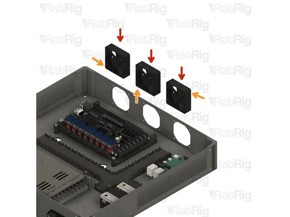
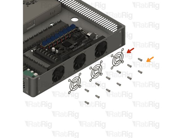
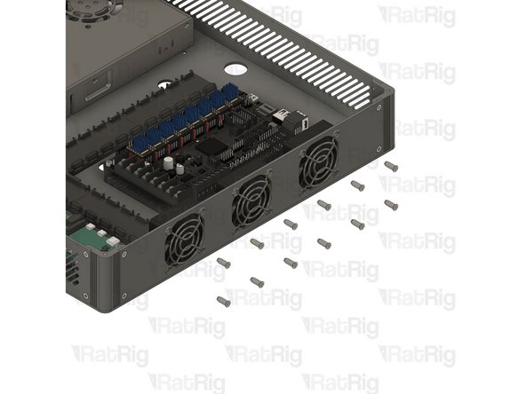
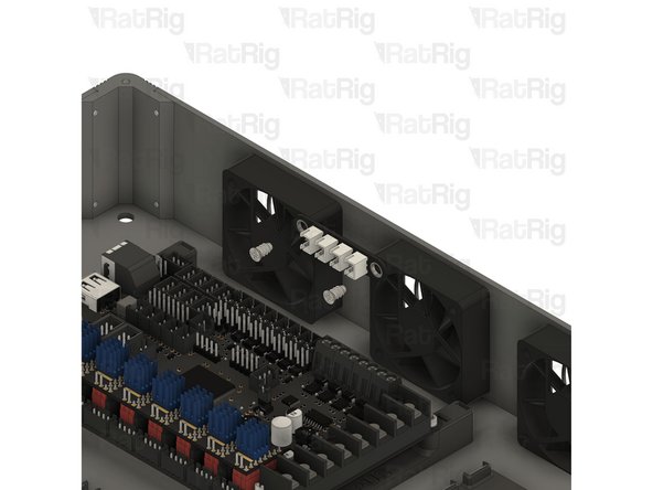
3x Fan 50x15 Axial
-
Ensure the wires are located where the arrows point.
-
Carefully look for the airflow direction, they should be pointing towards the octopus board, pulling fresh air from the outside.
-
-
-
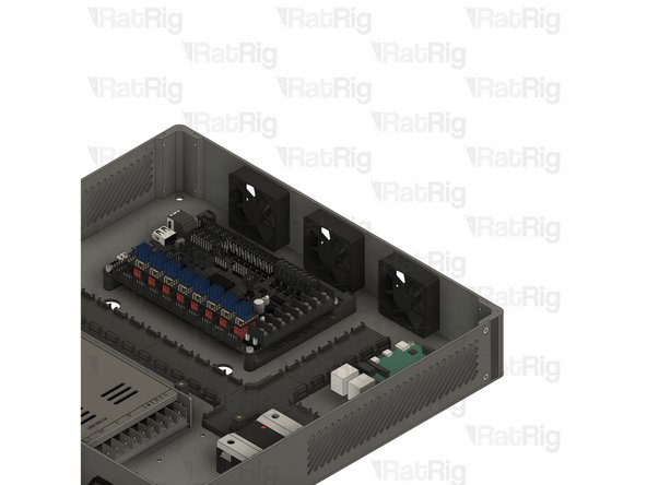
3x Fan Grille - 50mm
-
12x Self Tapping Screw - Fan - 12mm
-
Insert the screws through the fan grills and the electronics enclosure and thread them to the fans
-
Do not overtighten the screws as the fan bodies are sensitive.
-
-
-
Rat Rig 3-to-1 XH Splitter - 2 Pin - V1
-
2x Self Tapping Screw - Fan - 8mm
-
Insert the screws through the splitter and thread them to the fans
-
Do not overtighten the screws as the PCB and the fan bodies are sensitive
-
-
-
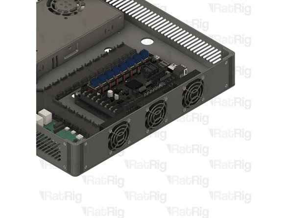
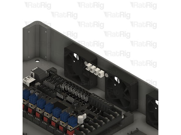
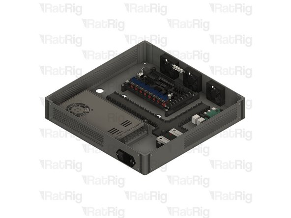
The assembly should look like the picture, take your time to double-check the orientation of every component,
-


Cancel: I did not complete this guide.
2 other people completed this guide.
