Reputation over time
It looks like this user hasn't gained any reputation yet.
Once they have, you'll be able to view a graph of their reputation gained over time.
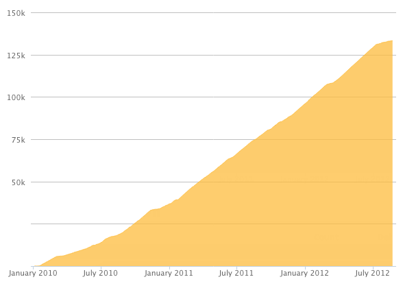
Here's a preview of what the graph will look like:
Reputation Breakdown
No reputation gained yet.
710
As recommended in Section 09_Gantry Alignment Step 4, be sure to rotate the pulley or motor shaft slightly to make sure that one of the two setscrews in the pulley tightens down squarely on the "flat" on the motor shaft.
The images above could be enhanced by the use of "break lines" across the red and black wires, to indicate that they are much, much longer than what's shown in the images. In my 300mm bed size kit, I had 1000mm and 1500mm cables to choose from.
Be sure to insert all of the magnets in the door printed parts with the north or south pole (your choice) down into the holes.
Then starting in Step 15 on the frame printed parts, insert all of the magnets with the opposite pole down in the holes, so they all attract when the panels are put in place.
FYI: With my printer, the magnets were a tight press fit in the frame parts, but were loose in the door parts, so I glued them in with cyanoacrylate super glue.
The second image above correctly shows the bed thermistor connecting to the bottom connector, but the text incorrectly states the "second thermistor slot, counting from the bottom."
A quantity of 17 M6 cap head screws, washers, and T-nuts are used to attach the rear panel, not 16.
The instruction above with the green dot reads, "Crimp the +12V (RED) wire to the left slot on the housing"
but it should read "right slot."
In the second image above, the Y1 (dark blue) motor cable is shown going to the 6th connector, but it should go to the 2nd connector.
The instruction above with the blue dot that reads, "Insert the other end on the SSR Relay positive terminal."
should instead say, "Insert the other end on the SSR Relay negative terminal."
The red and black wires that go to the power supply should connect to the right most pair of positive and negative terminals, not the left most terminals. This works if you followed the advice in the comment in Step 55.
The red and black wires that go to the power supply should connect to the left most pair of positive and negative terminals, not the right most terminals. This will leave room for the wires to reach in Step 57.
Page 1 of 3
Next