Reputation over time
It looks like this user hasn't gained any reputation yet.
Once they have, you'll be able to view a graph of their reputation gained over time.
Here's a preview of what the graph will look like:
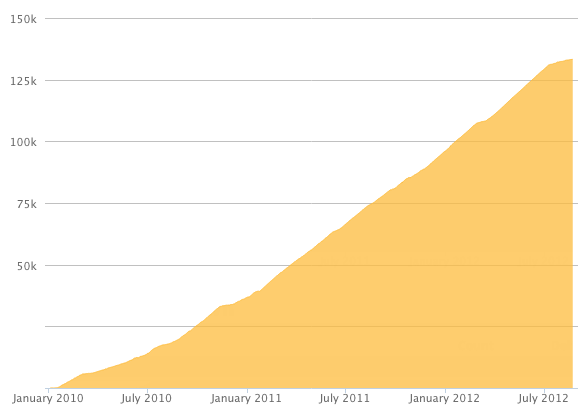
Reputation Breakdown
No reputation gained yet.
724
Should this start with "If your back panel..."?
(I wound up with a Batch 1 kit/bottom plate, and Batch 2 enclosure panels, so don't have either hole, oops.)
Shouldn't there also be 4x M2.5 Heat Inserts to match the 4x M2.5CHS for the Raspberry Pi brackets?
I would suggest this diagram and the text should call out the difference between the male and female crimp connectors in a larger diagram. (My kit supplied 4x of both kinds of connectors in a single bag, and a builder unfamiliar with micro-fit might not notice the difference.)
As with Step 72, this step can be performed before the fan is mounted to the x-rail (and would be much easier, as the rail is in the way once it is mounted.)
Clearer details on exactly how the USB cable is routed around the zip tie mounts would be appreciated.
Same comment as on step 18: make sure the "flat" on the stepper motor is accessible, for later fastening of the pulley.
I'd suggest that the builder should check the position of the "flat" on the stepper motor, at this step, and confirm it is on a side within the printer volume. The position shown in diagram #1 (red) should be ok, but it might be better to position it towards the front of the printer.
Making sure the "flat" is aimed towards the builder will help tighten one grub screw on the pulley to the flat, as mentioned in a comment to Step 4 of guide 9: Gantry Alignment.
I ran into a clearance issue: I cannot bring the X-axis gantry forward all the way because the joiners collide with the tensioner arms.
If the tensioner arms should not be colliding with the joiners prior to tensioning, then I suggest Step 27 of the the Motion System instructions should provide guidelines for an acceptable position for the tensioner arms. They seem to need about ~25mm maximum protrusion to avoid collision at this step. (Perhaps a more specific position is desirable based on the expected amount of positive/negative adjustment that will be needed.)
In the kit, my Phaetus Rapido V2 UHF did not come with a nozzle installed, and there are not any steps in these instructions that actually indicate the nozzle should be installed.
There should be a check that the volcano nozzle is installed here, with diagram before possibly skipping to step 26 and never giving instructions that it's important to use the volcano nozzle instead of the regular nozzle (both of which are included with the phaetus).
I'd suggest adding a third diagram to show the PTFE tubing is expected to be sticking out after being inserted, which is only next shown in diagram 2 of step 28.
Page 1 of 3
Next