
-
-
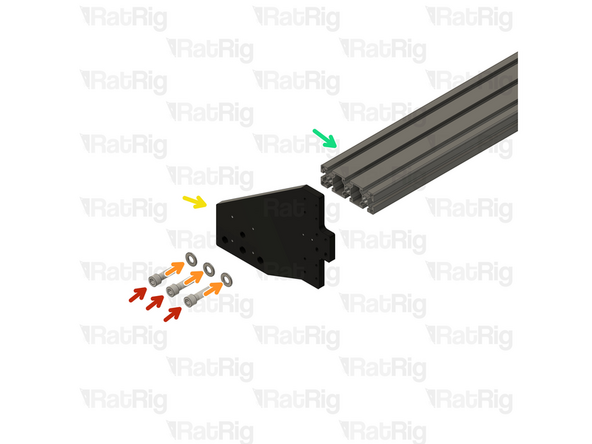
1000mm 40120 Extrusion
-
1500mm for the StrongHold ONE 1250x1250
-
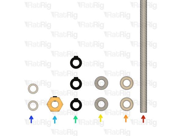
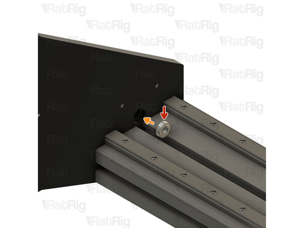
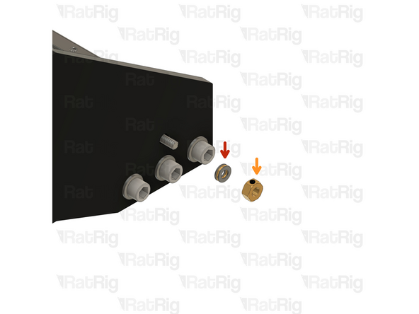
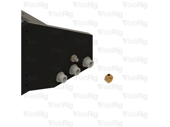
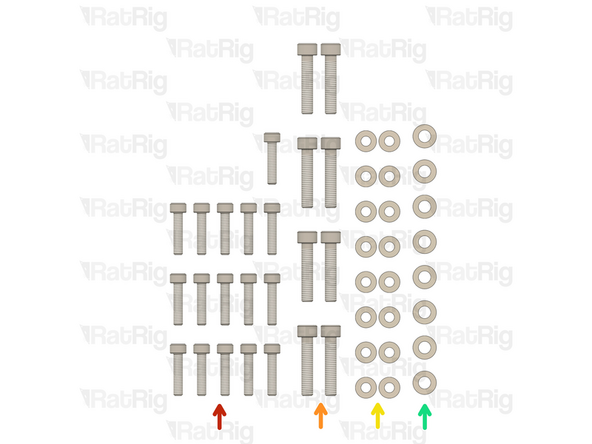
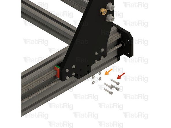
6x M12 Washer
-
6x M12x45 Cap Head Screw
-
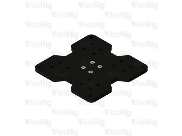
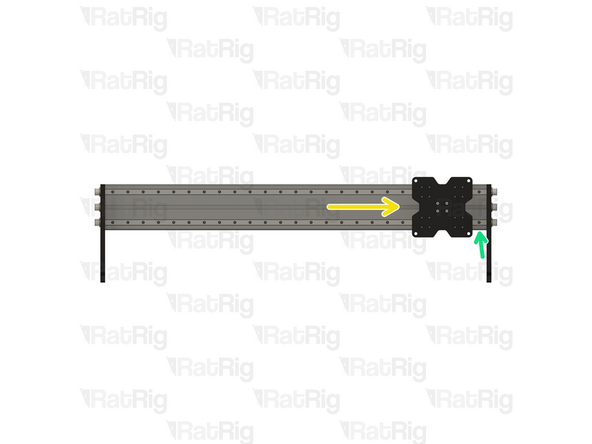
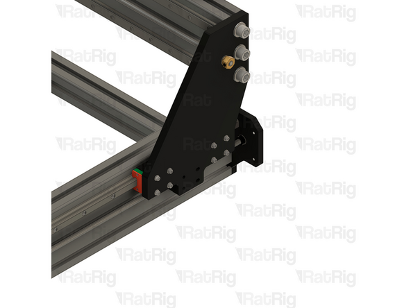
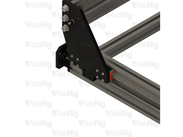
Rat Rig StrongHold ONE CNC - XY Joiner Plate Left
-
Rat Rig StrongHold ONE CNC - XY Joiner Plate Right
-
-
-
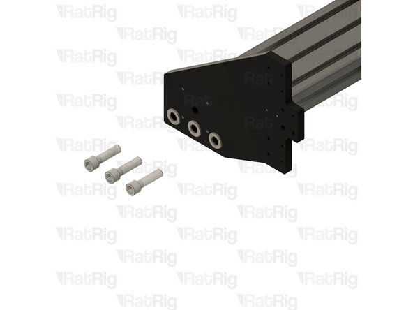
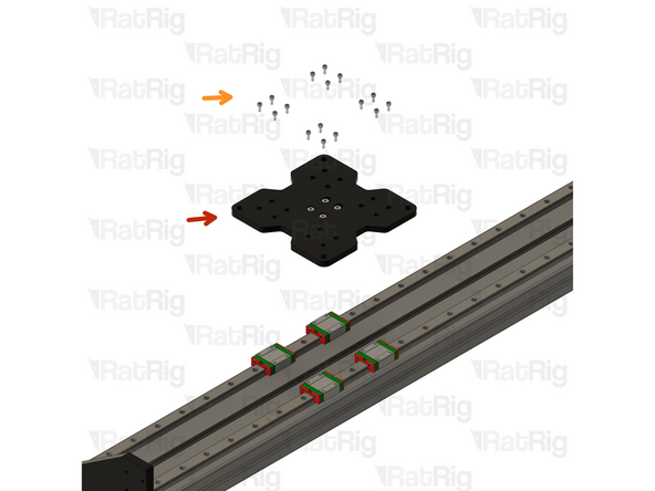
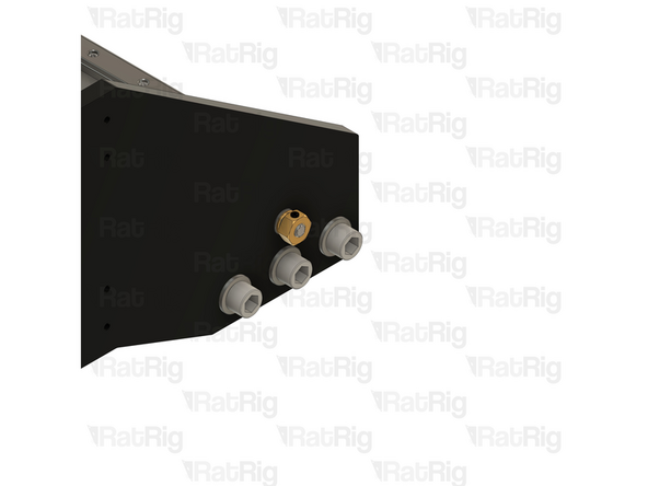
3x M12x45mm Cap Head Screw
-
3x M12 Washer
-
Rat Rig StrongHold ONE CNC - XY Joiner Plate Right
-
1000mm 40120 Extrusion
-
1500mm for the StrongHold ONE 750x1250 or 1250x1250
-
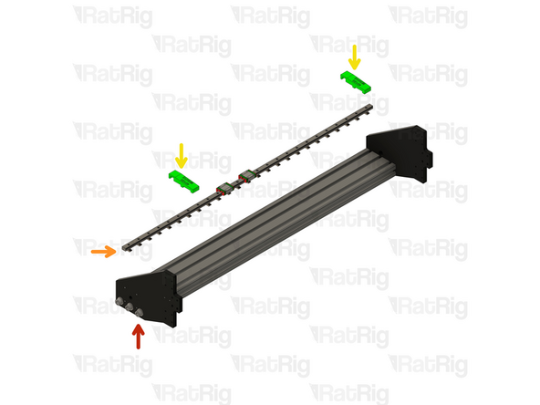
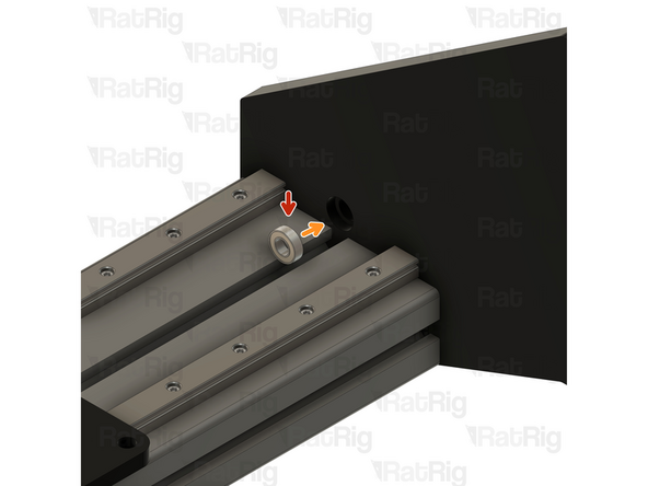
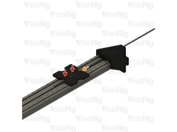
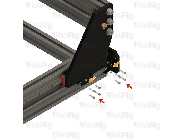
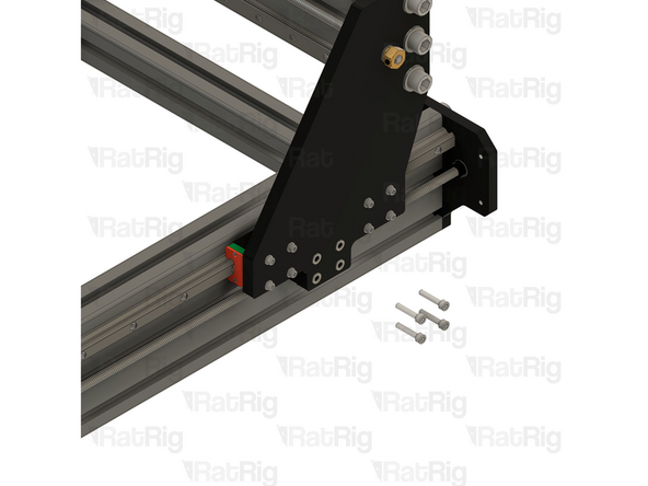
Place an M12 washer on to each M12x45 cap head screw and loosely screw them through the plate and in to the extrusion
-
-
-
3x M12x45mm Cap Head Screw
-
3x M12 Washer
-
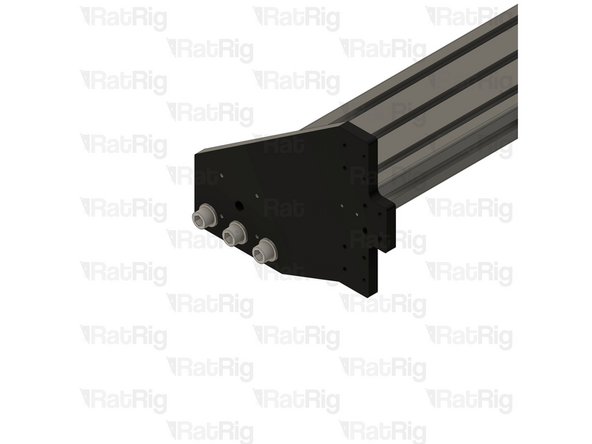
Rat Rig StrongHold ONE CNC - XY Joiner Plate Left
-
Assembly from the previous step
-
Place an M12 washer on to each M12x45 cap head screw and loosely screw them through the plate and in to the extrusion
-
-
-
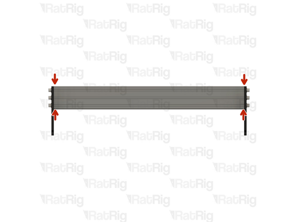
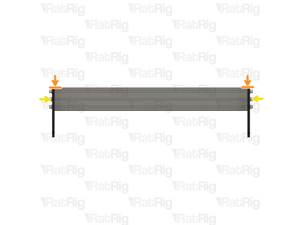
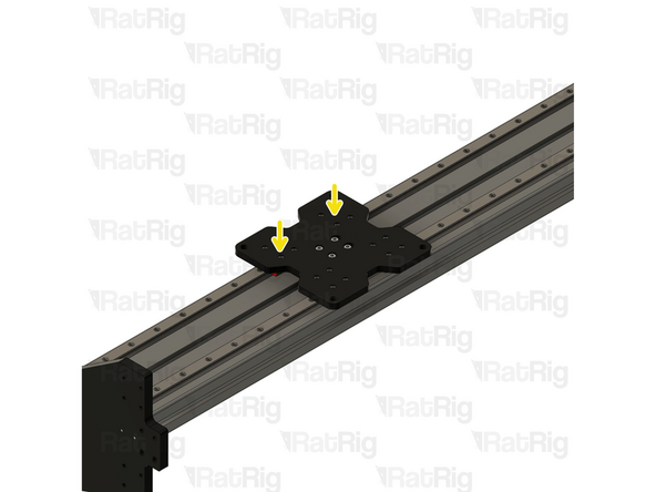
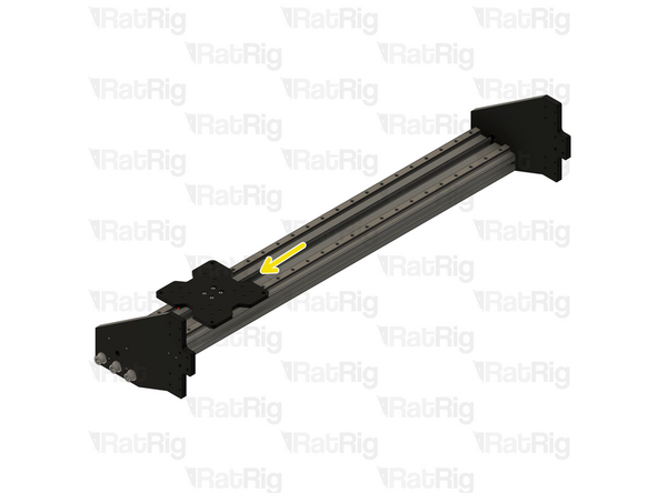
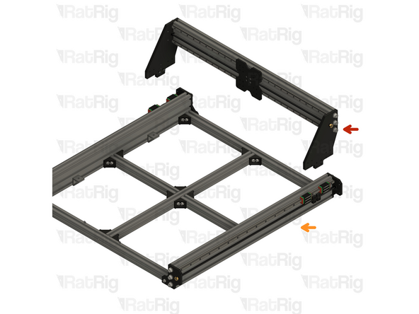
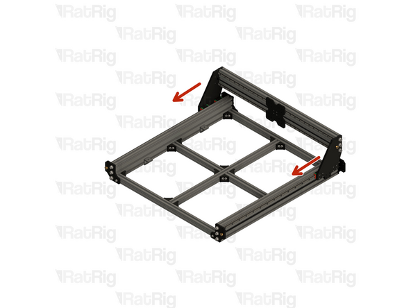
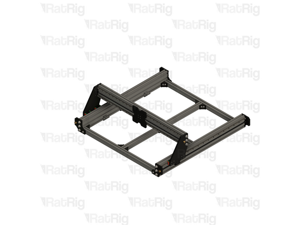
Before continuing with the assembly, the gantry must be squared and all screws full tightened
-
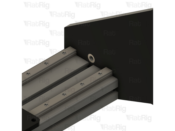
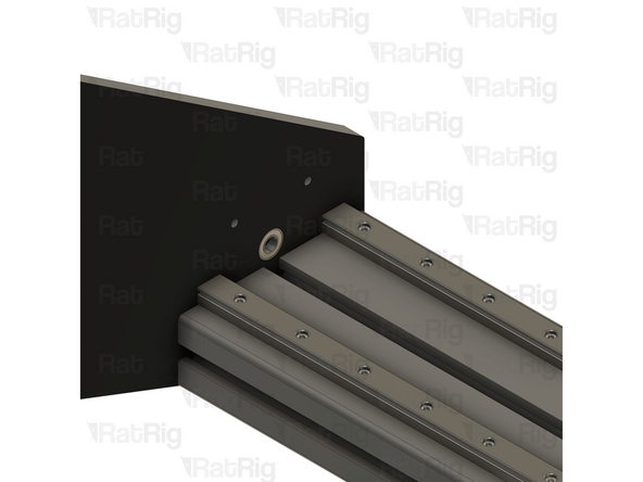
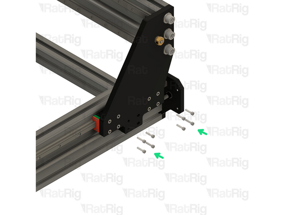
Ensure the extrusion and the plates are pressed together with no gaps. If clamps are available, the assembly can be optionally clamped together for the remainder of this step.
-
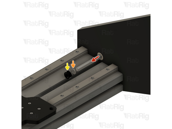
Using an engineers square, or a flat edge, check that the side plates are flush with the extrusions at the top of the gantry
-
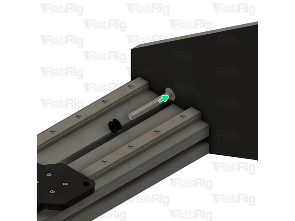
Fully tighten all six M12x45 screws on both ends of the gantry to secure everything together
-
Verify that all parts of the X-axis gantry assembly are still correctly aligned and adjust as necessary
-
-
-
2x Linear rail MGN15 1000mm
-
1500mm for the StrongHold ONE 1250x1250
-
50x M3x16mm Cap Head Screw
-
74x for the StrongHold ONE 1250x1250
-
50x 4040 Drop-in T-Nut M3
-
74x for the StrongHold ONE 1250x1250
-
2x Align 40120 MGN15 Printed Part
-
-
-
The linear rails are supplied with a protective oil coating on them. It is strongly recommended to prepare your work surface with paper towels and to wear disposable gloves.
-
Paper Towels
-
Linear Rail
-
With the rail still on the absorbent paper towels, carefully and slowly move the carriage from one end of the rail to the other
-
Small changes in resistance are normal, but the carriage becoming very hard to push, or binding completely are not
-
If the carriage does not move smoothly, or binds completely, refer to the Linear Rail Troubleshooting Guide
-
The linear rail carriages are not interchangeable. Do not try to use a carriage on a different linear rail than the one it was supplied with.
-
-
-
Do not allow the linear rail carriages to leave the end of the rail at any point
-
MGN15 Linear Rail
-
Insert an M3x16 cap head screw in each of the holes on the linear rail
-
Loosely thread a 4040 T-Nut on to each of the M3x16 screws
-
Repeat these instructions for the second linear rail
-
-
-
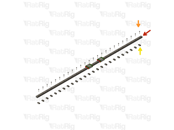
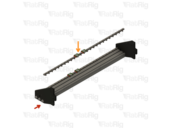
StrongHold ONE X-Axis Gantry Assembly from Step 3
-
MGN15 Linear Rail Assembly from the previous step
-
Install the two MGN15 40120 alignment tools as shown, this will make sure the linear rail is positioned correctly
-
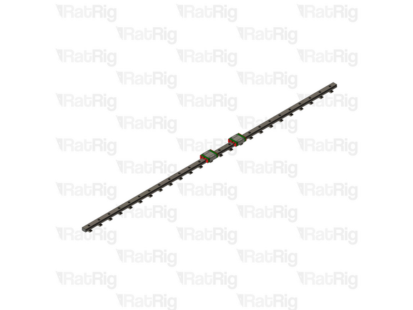
Tighten every other M3x16 screw, starting from one end
-
Tighten the remaining M3x16 screws, starting from the same end as before
-
Remove the MGN15 40120 alignment tools
-
-
-
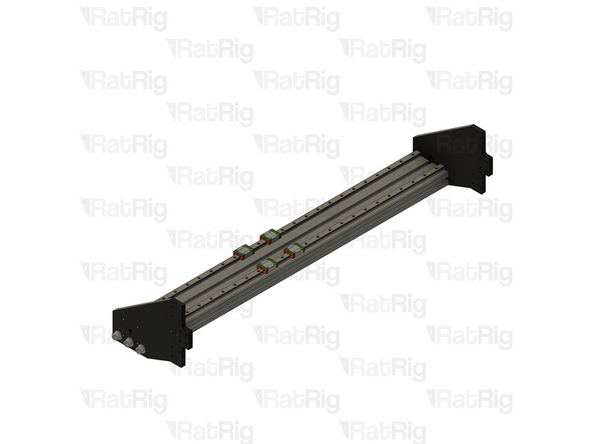
Assembly from the previous Step
-
Linear rail MGN15 1000mm
-
1500mm for the StrongHold ONE 1250x1250
-
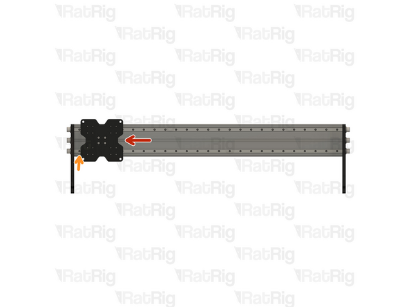
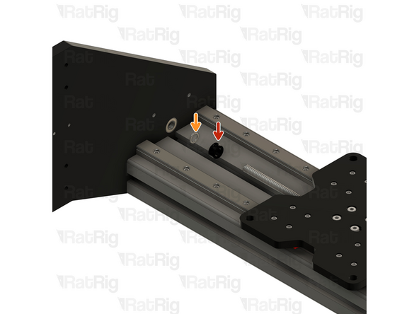
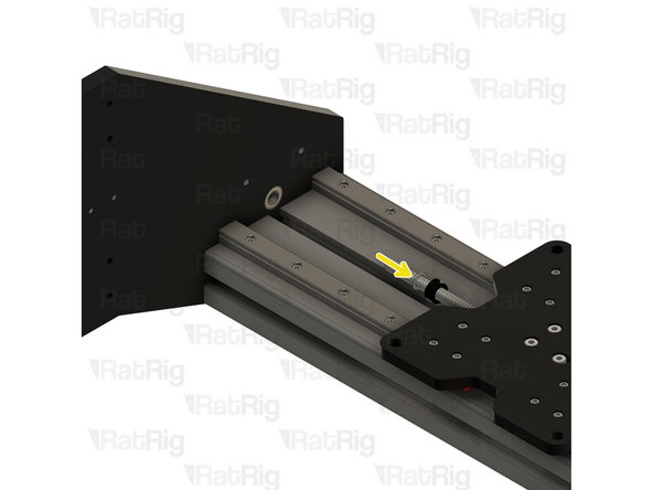
Place the linear rail on to the 40120 extrusion as shown, do not tighten any of the screws at this point
-
-
-
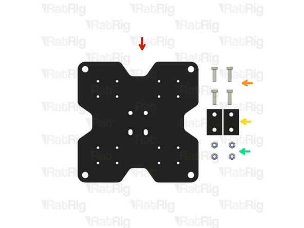
Rat Rig StrongHold ONE CNC XZ Joiner Plate
-
4x M5x16 Low Profile Cap Head Screw
-
2x Nut Block for TR8x8
-
4x M5 Nylon Locking Hex Nut
-
-
-
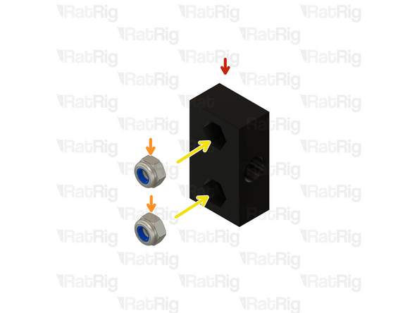
Nut Block for TR8x8
-
M5 Nylon Locking Hex Nut
-
Insert the M5 Locking Hex Nuts in to the Nut Block
-
-
-
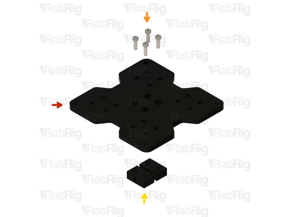
Rat Rig StrongHold ONE CNC XZ Joiner Plate
-
M5x16 Low Profile Cap Head Screw
-
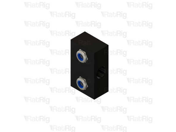
Nut Block assembly
-
Assemble the components in the shown order and make sure the nuts on the Nut Blocks are not facing the XZ Plate.
-
-
-
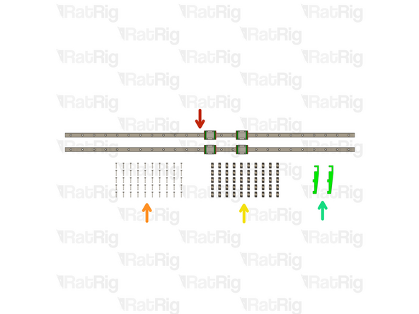
Rat Rig StrongHold ONE CNC XZ Joiner Plate
-
16x M3x8mm Cap Head Screw
-
Position the MGN15 linear rail blocks so that the holes align with those on the XZ joiner plate
-
Install an M3x8 Screw through each hole in the plate, and in to the MGN15 linear rail carriage below, lighty tighten them
-
-
-
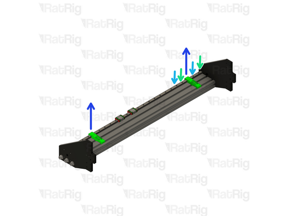
Push the XZ Plate to the left
-
Tighten the first M3x16 screw on the bottom rail
-
Push the XZ Plate to the right
-
Tighten the last M3x16 screw on the bottom rail
-
Tighten every other M3x16 screw, starting from one end
-
Tighten the remaining M3x16 screws, starting from the same end as before
-
If the X-axis binds or becomes tight, check that the lower rail is aligned correctly. Loosening the screws securing the lower rail to the 40120 extrusion and repeat the steps above. Do not overtighten the screws as it can cause the axis to bind.
-
Tighten the M3x8 Cap Head Screws on the XZ Plate.
-
-
-
1057mm TR8x8 Lead Screw (1557mm for a 1250x1250 machine)
-
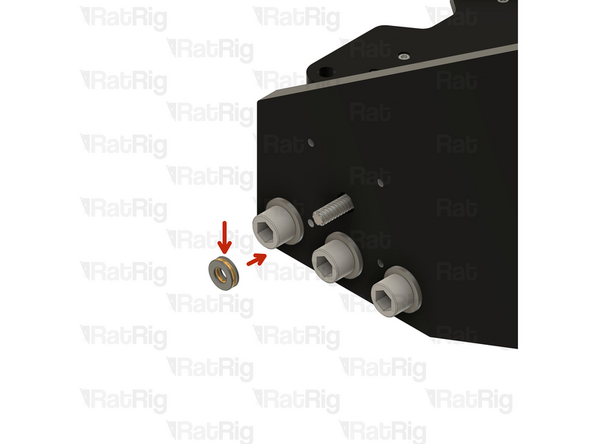
2x 688ZZ Ball Bearing
-
2x Thrust Bearing F8-16M
-
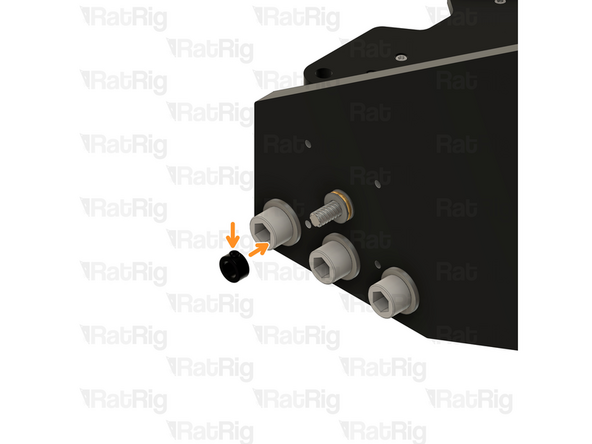
3x Lock Collar 8mm
-
Lead Screw Tensioning Nut
-
2x Precision Shim 12x8x1mm
-
-
-
688ZZ Ball bearing
-
Push the ball bearing against the inner side of the plate.
-
-
-
688ZZ Ball bearing
-
Push the ball bearing against the inner side of the plate.
-
-
-
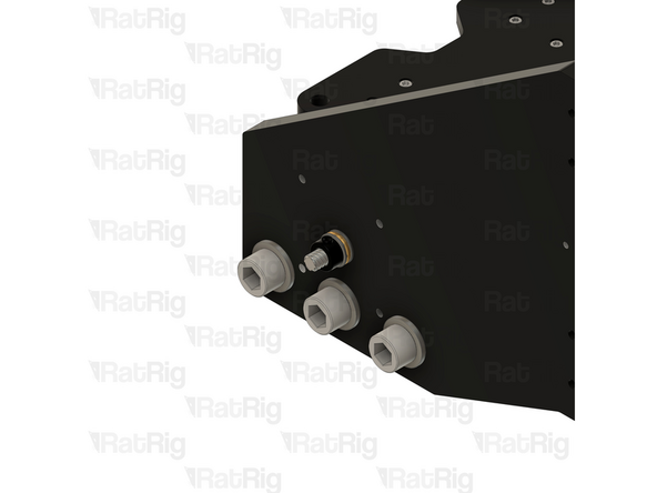
While performing this step, make sure to support the Lead Screw to prevent it from bending
-
Push the Lead Screw through the hole in the ball bearing
-
Precision Shim 12x8x1mm
-
Lock Collar
-
Slide the Precision Shim on to the Lead Screw
-
Slide the Lock Collar on to the Lead Screw
-
-
-
Nut Block for TR8x8
-
Screw the Lead Screw through both Nut Blocks under the XZ Plate.
-
Push the assembly to the left
-
-
-
Lock Collar
-
Do not tighten the screw on the Lock Collar yet.
-
Precision Shim 12x8x1mm
-
Slide the Precision Shim and the Lock Colar on to the Lead Screw
-
Push the Lead Screw through the Ball Bearing on the XY plate
-
-
-
Thrust Bearing F8-16M
-
Install the Thrust Bearing on to the exposed end of the Lead Screw as shown
-
Lock Collar
-
Install the Lock Collar on to the Lead Screw, don't tighten the screw yet
-
-
-
Thrust Bearing
-
Tensioner Nut
-
Install the Thrust Bearing on to the exposed end of the Lead Screw as shown.
-
Screw the Tensioning Nut on to the end of the lead screw.
-
Do not tighten the screw on the Tensioner Nut yet.
-
-
-
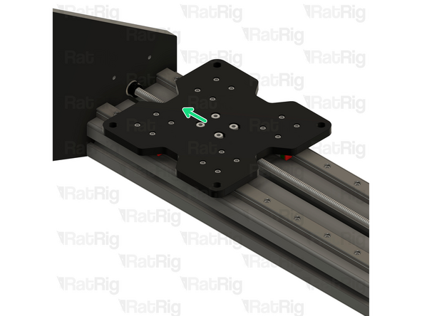
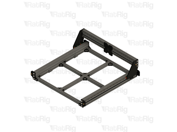
X - Gantry Assembly
-
Frame Assembly
-
It is highly recommended to have two or more people for the next few steps in particular
-
The X-Axis gantry is large and heavy and can cause injury if it were to fall
-
When lowering the X-axis gantry, make sure the plates at either end do not collide with the linear rail carriages or the lead screw components
-
Continue to support the X-axis gantry as it may tip forwards or backwards until secured
-
-
-
16x M4x18 Cap Head Screw
-
16x M4 Washer
-
8x M5x25 Cap Head Screw
-
8x M5 Washer
-
-
-
At least one other person should continue to support the X-axis gantry during this step
-
Align one of the HG15 linear rail carriages with the holes on the X-axis gantry plate
-
8x M4x18 Cap Head Screw
-
8x M4 Washer
-
Install an M4 washer on to each of the M4x18 screws, then insert them through the X-axis gantry plate, the HG15 spacer plate, and screw them into the MGN15 linear rail carriage
-
-
-
Repeat the previous steps for the left side of the assembly
-
-
-
Slowly and carefully move the X-axis gantry over the full length of the axis
-
Be mindful of the Nut Blocks, do not allow the gantry to collide with them!
-
-
-
4x M5x25 Cap Head Screw
-
4x M5 Washer
-
Once all four holes are aligned, install an M5 washer onto each M5x25 screw and insert them through the gantry plate, tightening them into the nut block
-
Repeat these instructions to secure the nut block to the other side of the X-axis gantry
-


Cancel: I did not complete this guide.
One other person completed this guide.

One Comment
Hi Miguel, Great instructions, thanks. The image in step 23 shows the MGN15 linear rail carriages attached to the X gantry, but by this point they would be on the Y axis rails. I wonder if it might be better to change this if possible?
Robert Merwiak - Resolved on Release Reply