Introduction
This guide provides a thorough overview of the disassembly of the EVA3, the preparation of the V-Core 3.1 frame, and the installation procedure for the Rat Rig toolhead Upgrade Kit.
The Rat Rig Toolheads are streamlined to be used specifically with our favourite combination:
Orbiter V2
Phaetus Rapido V2 UHF hot end
4028 part cooling fan
Rat Rig “SuperPinda” Probe by P&F
-
-
This guide is divided into 3 parts, to help you quickly find the instructions you need:
-
Disassembling the EVA 3.0
-
-
-
-
-
Remove the M3x25 Cap Head Screw
-
Remove the Hex Nut - M3
-
Remove the M3 Nylon Locking Hex Nut
-
Remove the M3x35 Cap Head Screw
-
Remove the 40mm_fan_duct assembly as shown
-
-
-
Remove the four M3x35 Cap Head Screws
-
Remove the 4028 Part Cooling Fan from the printed part, it will be re-used on the Rat Rig Toolhead V1.0
-
Remove the four Hex Nuts - M3
-
-
-
Remove the two M3x8 Cap Head Screws
-
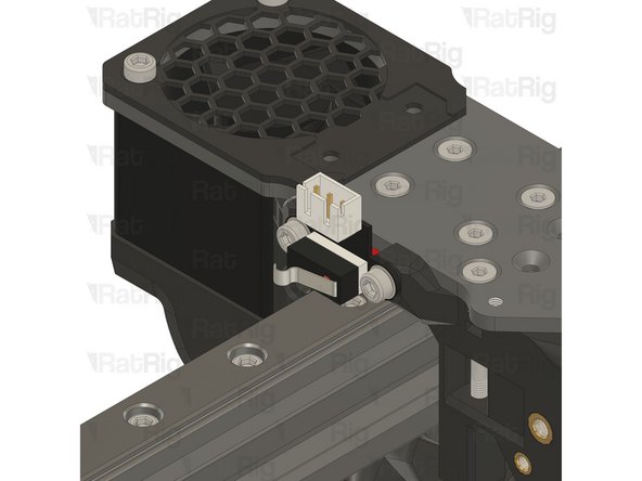
Disconnect the Endstop Module and set it aside, it will be re-used on the Rat Rig Toolhead V1.0
-
Loosen the M3x8 Cap Head Screw
-
Remove the Z-probe from the printed part, it will be re-used on the Rat Rig Toolhead V1.0
-
Remove the three M3x8 Cap Head Screws
-
-
-
Remove the four M3x20 Cap Head Screws
-
Remove the ratrig_eva3_shroud Printed Part
-
Remove the 4010 Axial Fan from the assembly, it will be re-used on the Rat Rig Toolhead V1.0
-
Remove the four M3x8 Cap Head Screws
-
-
-
Remove the four M3x8 Cap Head Screws
-
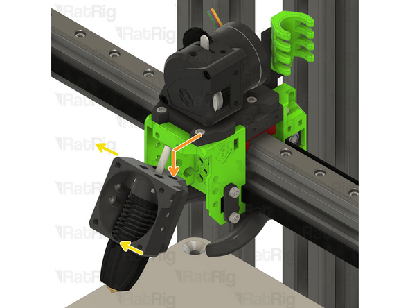
Gently push the hotend assembly down and away from the toolhead-
-
Rotate the hot end assembly into position as shown
-
-
-
Remove the PTFE line
-
Remove the four M2.5x8 Cap Head Screws
-
Remove the Rapido hotend from the printed part, it will be re-used on the Rat Rig Toolhead V1.0
-
Tip: Insert the four M2.5x8 Cap Head Screws back in the Rapido hotend mounting points to avoid losing them.
-
-
-
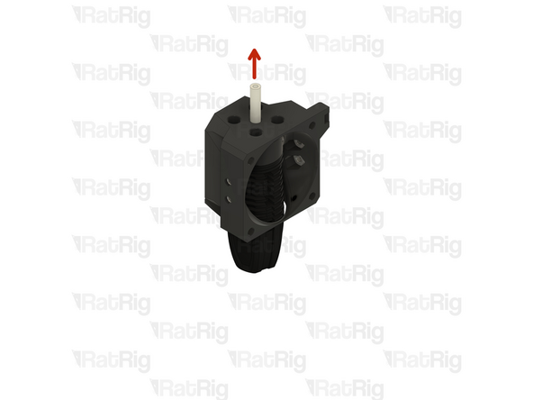
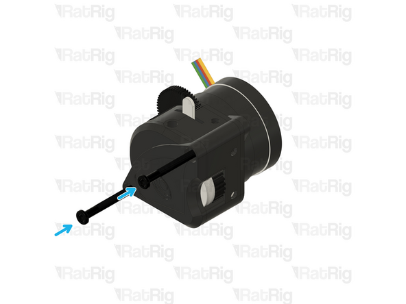
Remove the two M3x25 screws on the face of the LGX Lite which secure the motor in place
-
Remove the Bondtech LGX Lite motor from the back of the LGX Lite extruder
-
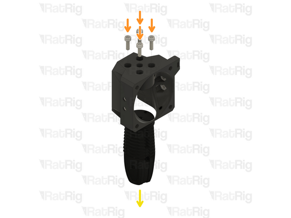
Remove the three M3x12 Cap Head Screws
-
-
-
Remove the two M3x8 Cap Head Screws
-
Remove the extruder assembly
-
The new Rat Rig toolhead uses the Orbiter V2,
-
Remove the M3x8 Cap Head Screws holding the LGX Lite to the EVA3 drive_lgx_lite Printed Part
-
Reassemble the LGX Lite so you can safely store it.
-
-
-
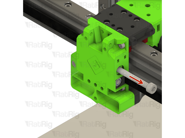
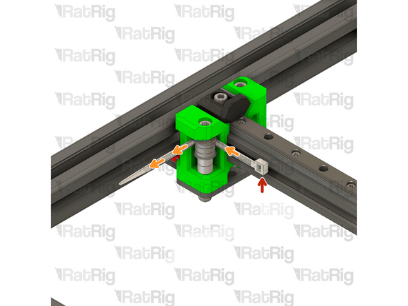
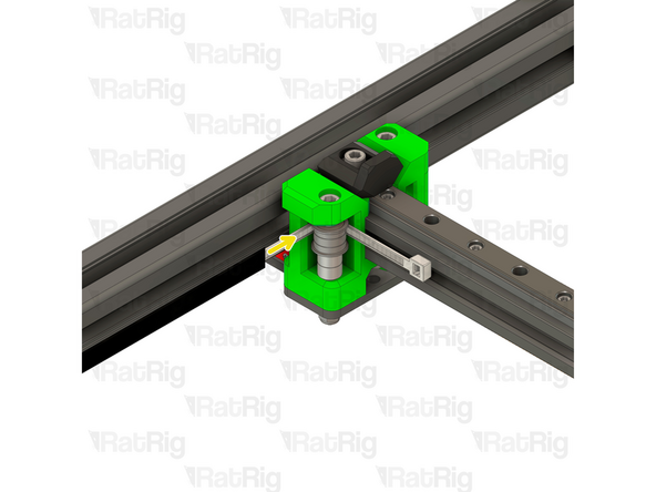
Loosen the M5x40 Cap Head Screw
-
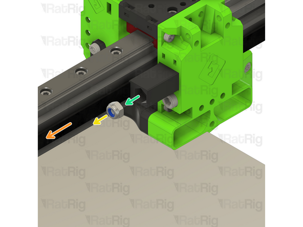
Pull the belt to help remove the CoreXY belt grabber
-
Remove the M5 nylon locking nut
-
Remove the belt grabber from the toolhead
-
Repeat the previous steps and remove the other CoreXY belt grabber
-
-
-
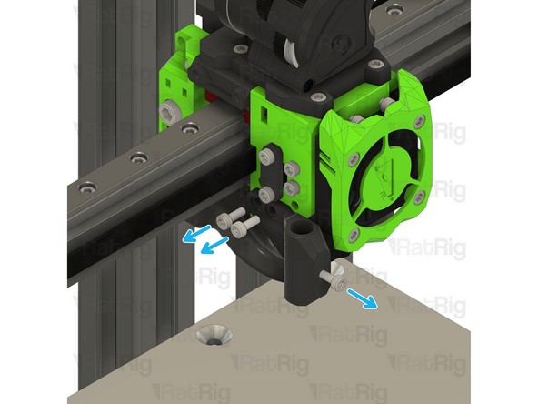
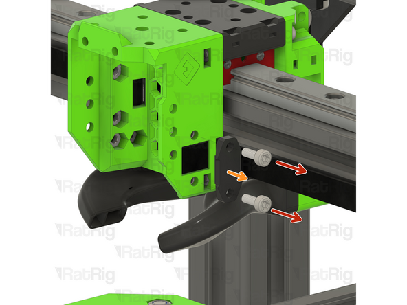
Remove the two M3x8 Cap Head Screws
-
Remove the belt front belt holder
-
Repeat the previous steps for the other front belt holder
-
-
-
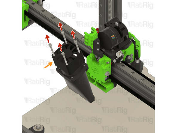
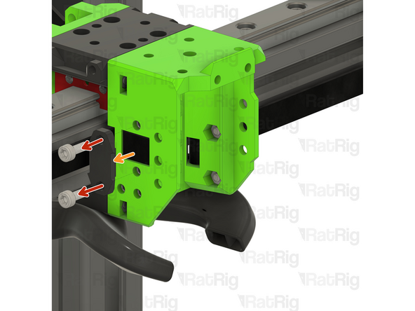
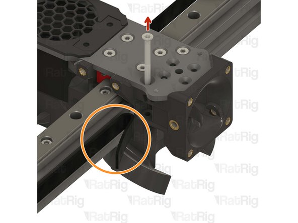
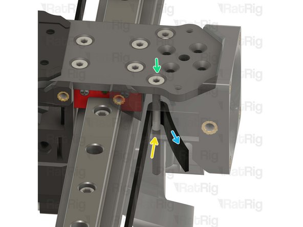
Remove the two M3x35 Cap Head Screws
-
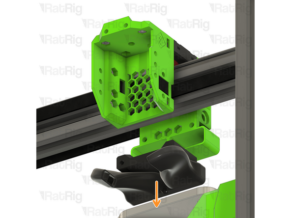
Pull down on the EVA horn ducts
-
-
-
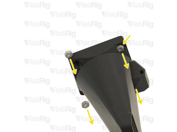
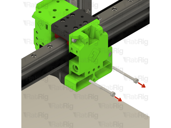
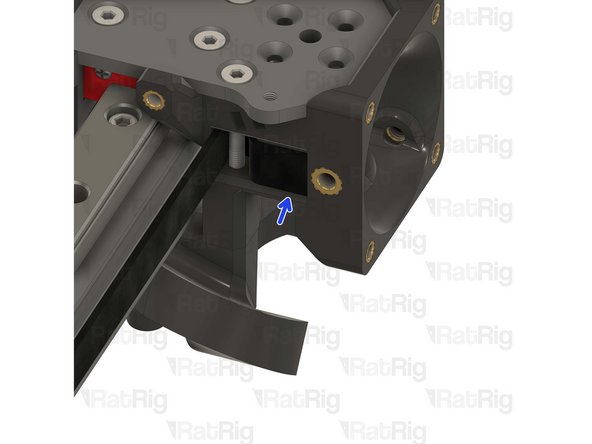
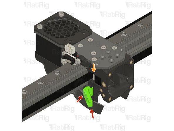
Remove the two M3x35 Cap Head Screws
-
Pull on the EVA3 front assembly to remove it
-
Pull on the EVA3 back assembly to remove it
-
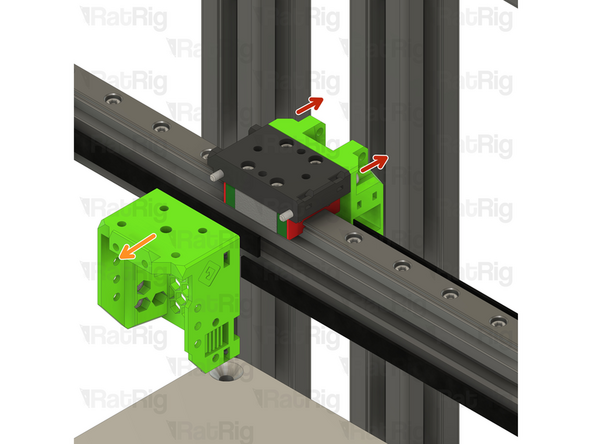
Remove the four M3x8 Cap Head Screws
-
Remove the EVA3 mgn12 mount
-
-
-
Some components of the V-Core 3.1 need to be upgraded to support the new Rat Rig Toolhead. The following steps will show you how.
-
-
-
Locate the rear cable holder
-
Remove the M6x12 Cap Head Screw
-
Remove the electronics_wire_guide_rear printed part from the frame
-
Remove the M6 3030 Drop in T-nut
-
Locate the Y endstop mount
-
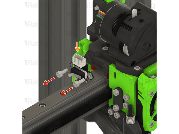
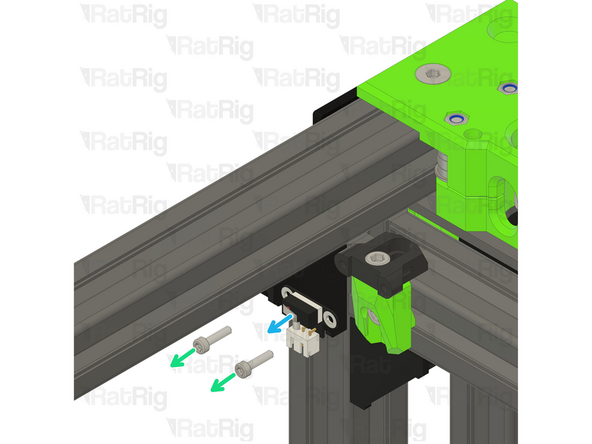
Remove the two M3x12 Cap Head Screws
-
Disconnect the Enstop Module and set it aside, it will be re-used on the Rat Rig Toolhead V1.0
-
-
-
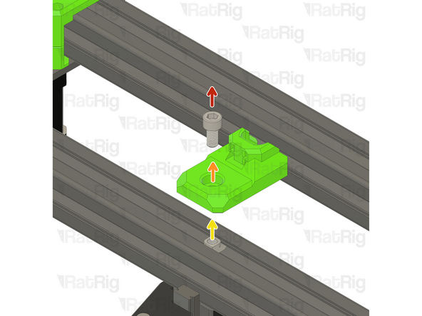
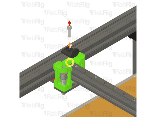
Remove the M5x12 Cap Head Screw
-
Remove the Y_max_endstop_slider printed part
-
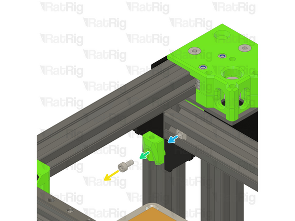
Remove the M5x10 Cap Head Screw
-
Remove the Y endstop_max_block printed part
-
Remove the M5 3030 Drop in T-nut
-
-
-
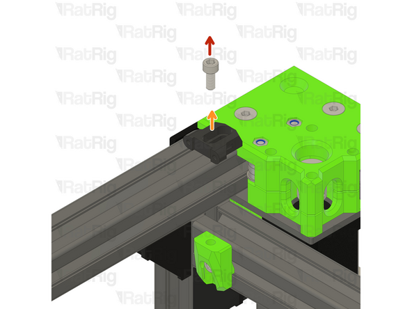
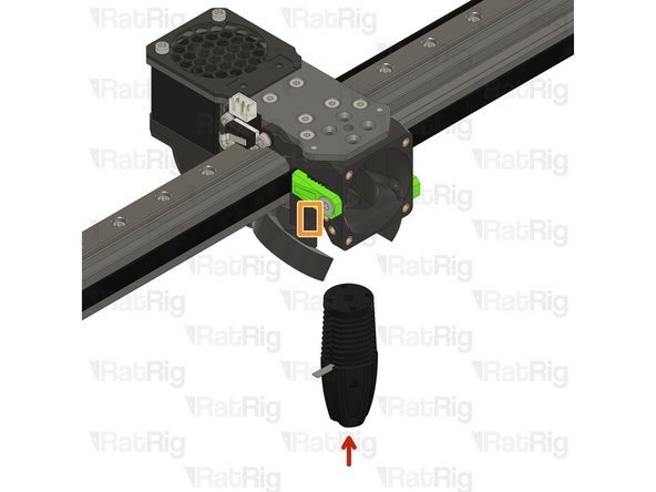
Remove the M5x18 Cap Head Screw
-
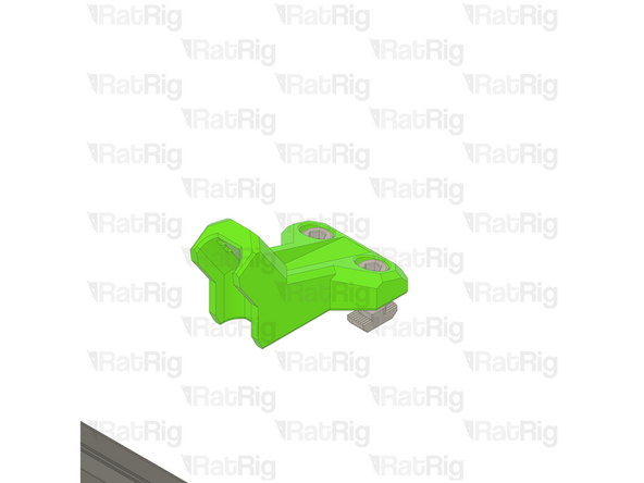
Remove the EVA3 endstop block
-
Avoid moving the machine around at this point, os the M5 Drop in T-nut doesn't slide around on the gantry extrusion.
-
-
-
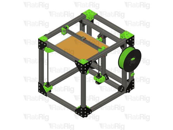
The V-Core 3.1 is now ready to receive the Rat Rig Toolhead V1.0 Upgrade kit
-
-
-
The next steps will cover the assembly of the Rat Rig toolhead V1.0 upgrade kit
-
-
-
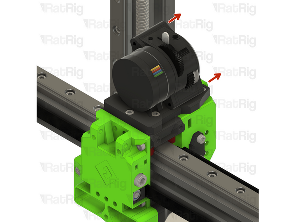
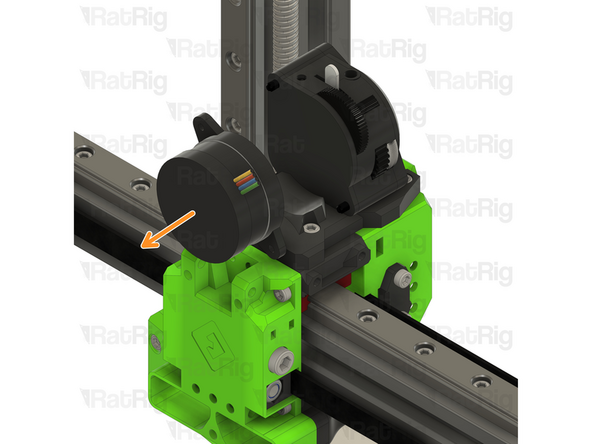
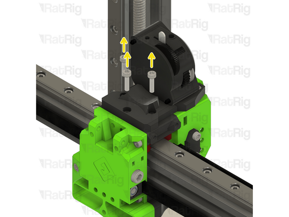
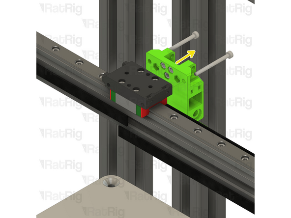
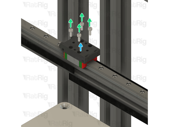
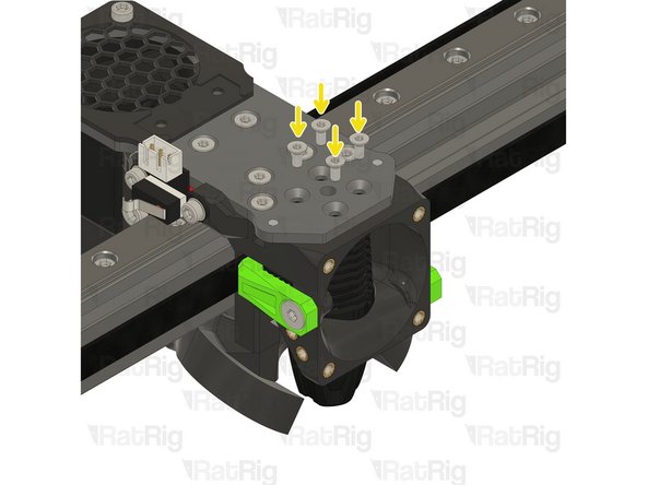
Remove the M3x45 Cap Head Screws
-
Remove the Stepper motor
-
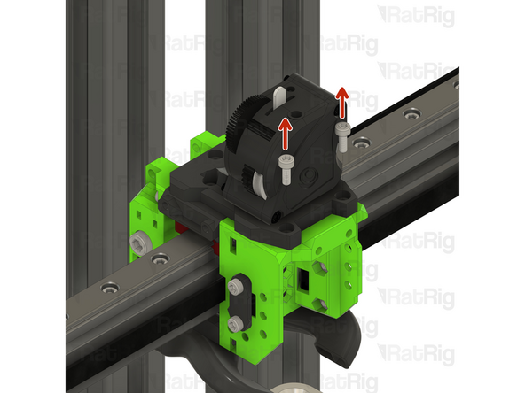
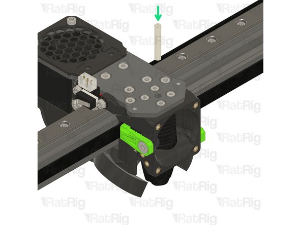
Remove the M5x40 Cap Head Screws
-
-
-
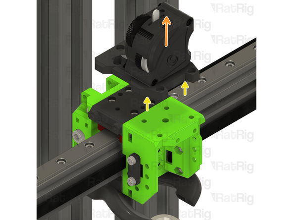
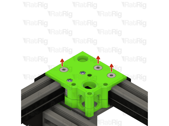
Remove the three M6x14 Screws
-
If the M6 Drop in T-nuts fall off, loosely thread them in the screws so you can easly reinstall the CoreXY motor cage top easily.
-
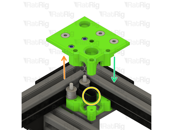
Remove the CoreXY motor cage top
-
Remove both of the old belts, then insert the two new ones following the same paths
-
Reinstall the CoreXY motor cage top
-
-
-
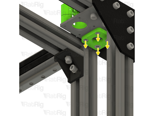
Tighten the three marked M6x14 screws to secure the CoreXY motor cage top to the frame
-
Tighten the M5x40 screws to secure the bearing stacks into the CoreXY motor cage top
-
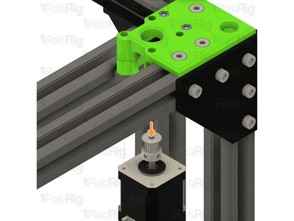
Position the NEMA17 motor up and into the motor cage from below, it will be secured in the next step
-
-
-
Insert the M3x35 screws into the xy_motor_cage_left_top as shown, and fasten them to secure the NEMA17 motor to the mount
-
Check the alignment of the timing pulley, the belt should be on the middle of the pulley as shown
-
Adjust the pulley up or down if required to make sure the belt is in the middle of the pulley
-
Fasten both M3 grub screws to securely mount the timing pulley to the NEMA17 motor shaft
-
Repeat Steps 21 - 24 for the other CoreXY motor mount cage.
-
-
-
This step is not mandatory, it's just a Rat Rig tip on how to feed the belts on the idlers.
-
Zip Tie
-
The wider the zip tie is, the easier the process will be
-
Bend the tip of the zip tie a little bit and feed it between the printed part and the idler, as shown
-
Insert the belt between the zip tie and the idler
-
Slowly feed the belt and pull the zip tie at the same time
-
-
-
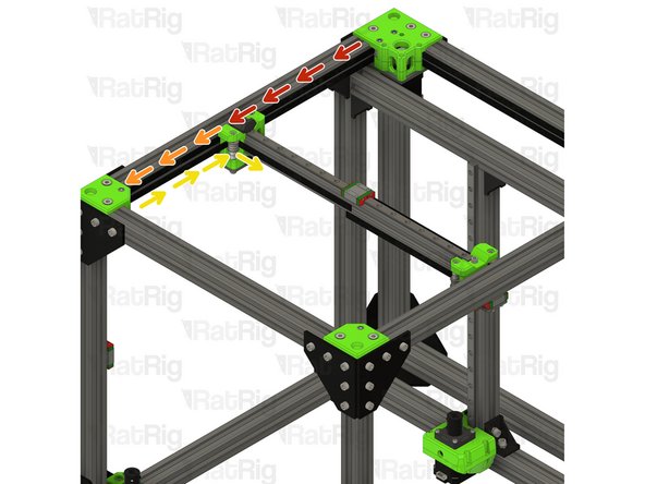
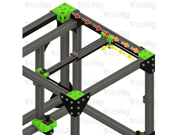
Take the loose end of the top CoreXY belt on the left hand side:
-
Feed the belt behind the left xy_joiner
-
Down and around the front xy_idler
-
Around the front bearing stack on the left xy_joiner
-
Take the loose end of the bottom CoreXY belt on the left hand side:
-
Feed the belt around the rear bearing stack on the xy_joiner
-
-
-
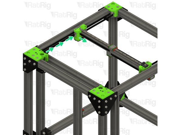
Take the loose end of the bottom CoreXY belt on the right hand side:
-
Feed the belt behind the right xy_joiner
-
Down and around the front xy_idler
-
Around the front bearing stack on the right xy_joiner
-
Take the loose end of the top CoreXY belt on the right hand side:
-
Feed the belt around the rear bearing stack on the xy_joiner
-
-
-
3x M6x12 Cap Head Screw
-
2x M3x8 Cap Head screw
-
3x 3030 M6 Drop In T-nut
-
Y endstop
-
Y_endstop printed part
-
Umbilical_frame printed part
-
-
-
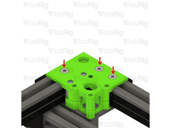
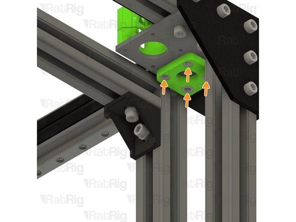
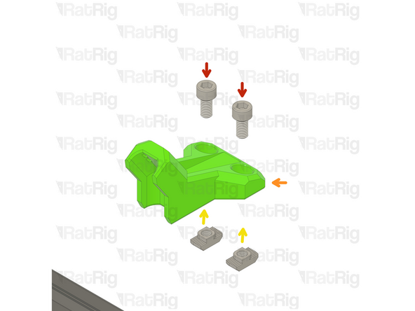
2x M6x12 Cap Head Screw
-
Install the M6 cap head screws into the printed part as shown.
-
Umbilical_frame printed part
-
3030 M6 Drop In T-nut
-
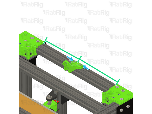
Loosely thread a 3030 M6 T-Nut onto the M6x12 screws. Do not tighten it at this point
-
Make sure the printed part is on the middle of the rear extrusion.
-
Tighten the M6x12 screw to secure the umbilical mount to the frame.
-
-
-
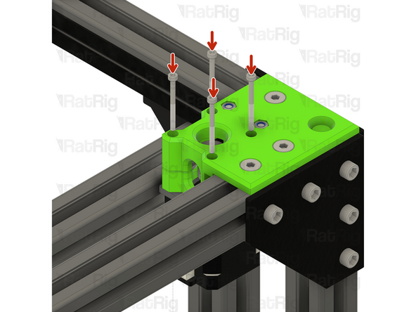
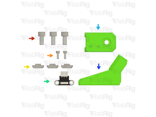
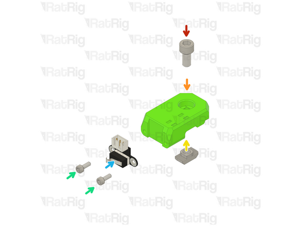
M6x12 Cap Head Screw
-
Y_endstop printed part
-
3030 M6 Drop In T-nut
-
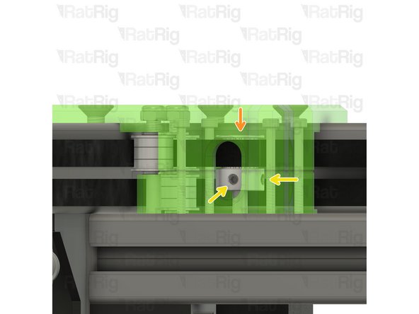
Loosely thread a 3030 M6 T-Nut onto the M6x12 screw. Do not tighten it at this point
-
2x M3x8 Cap Head Screw
-
Y Endstop
-
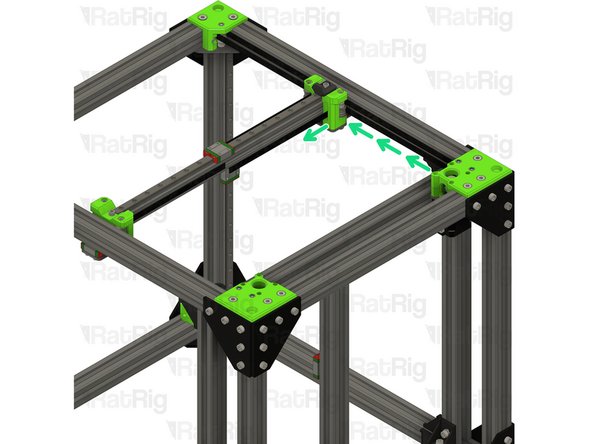
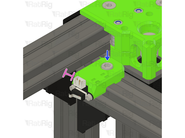
Tighten the M6x12 screws to secure the endstop mount.
-
Ensure a 5mm gap between the 3030 extrusion and the Y_endstop printed part, this distance is required for the belts to operate smoothly.
-
-
-
Rat Rig toolhead plate
-
Rat Rig toolhead front printed part
-
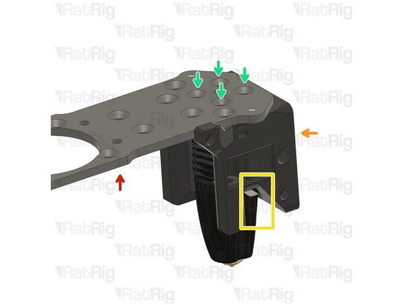
Insert the Rapido V2 into the printed part as shown, and make sure the cables are positioned in the designated slot.
-
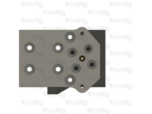
Look from above and see if all four holes line up correctly.
-
All the holes on the plate, hotend and printed part should line up:
-
If they align skip to step 35
-
If they don't align follow the next steps
-
-
-
If the cables of your Rapido 2 hotend don't align perfectly with the toolhead slot, please follow the next steps:
-
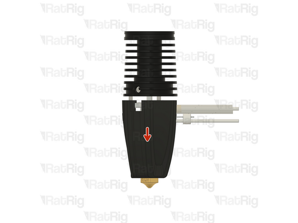
Push down on the silicone sock to remove it
-
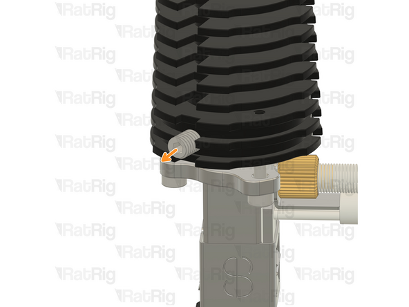
Loosen the set screw on the heatsink
-
Do not remove it completely to avoid losing it
-
-
-
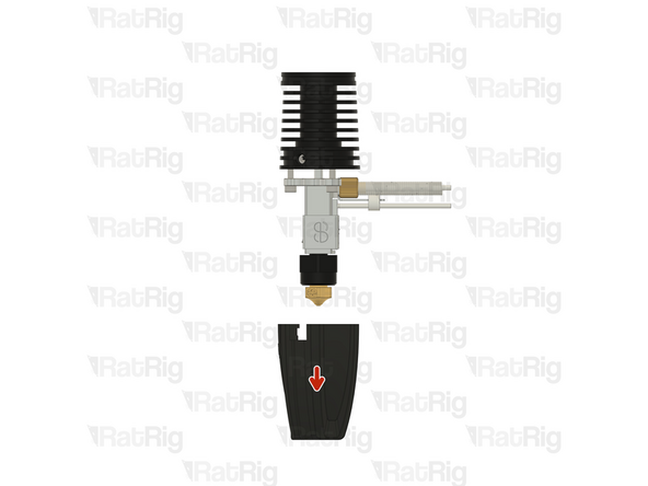
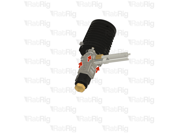
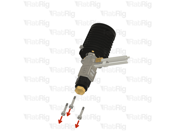
Remove the 2.5 Cap Head Screws from the hotend
-
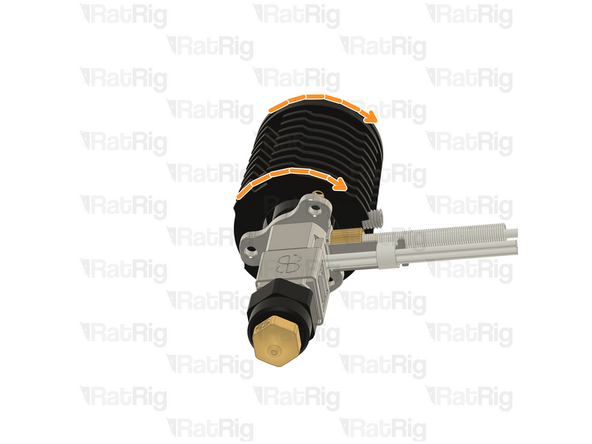
Carefully rotate the heatsink until the three screw holes align again.
-
There isn't a way to tell how much you need to rotate you hotend, it might be just 120º or it might be 240º. It's a matter of trial and error.
-
-
-
Insert the 2.5mm Cap Head Screws back in and tighten them.
-
DO NOT overtighten the screws, they are only 2.5mm and will break if excessive force is applied.
-
Tighten the set screw back in
-
DO NOT overtighten the screw, if excessive force is applied the heatbreak will be permanently damaged.
-
Put the socket back on
-
Try to insert the hotend on the toolhead and see if the cables align with the designated slot, if not, repeat steps 32-34 and try a different angle in step 34
-
-
-
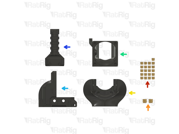
21x Heat insert M3
-
2x Heat insert M4
-
1x rr_toolhead_vc3_duct printed part
-
1x rr_toolhead_vc3_front printed part
-
1x rr_toolhead_vc3_back printed part
-
1x rr_toolhead_vc3_umbilical printed part
-
If you are not using a toolboard.
-
If you bought the printed parts from Rat Rig, the heat inserts are already in place. Skip to Step 39.
-
-
-
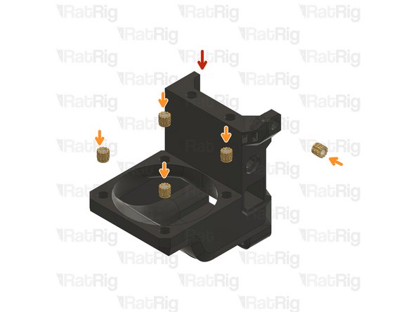
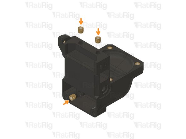
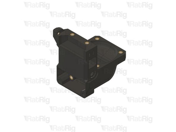
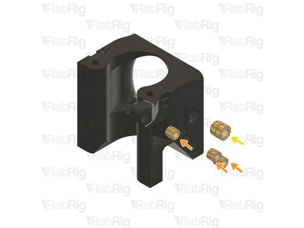
1x rr_toolhead_vc3_back printed part
-
8x Heat insert M3
-
-
-
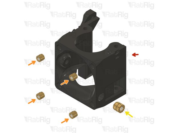
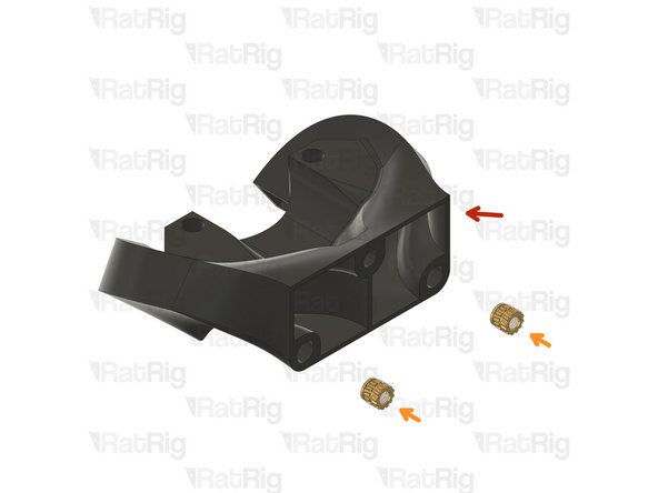
1x Rat Rig toolhead_front printed part
-
7x Heat insert M3
-
2x Heat insert M4
-
-
-
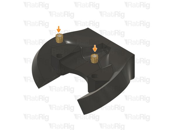
1x Rat Rig toolhead_duct printed part
-
4x Heat insert M3
-
-
-
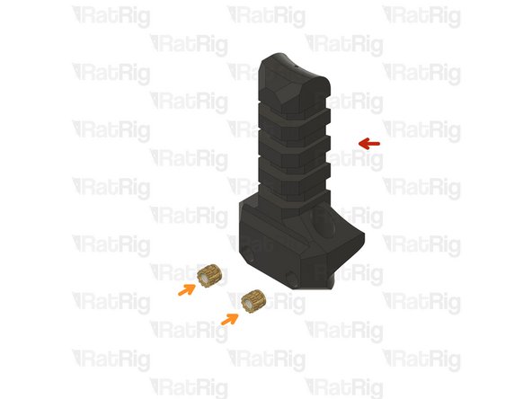
1x Rat Rig toolhead_umbilical printed part
-
2x Heat insert M3
-
If you are not using a toolboard.
-
-
-
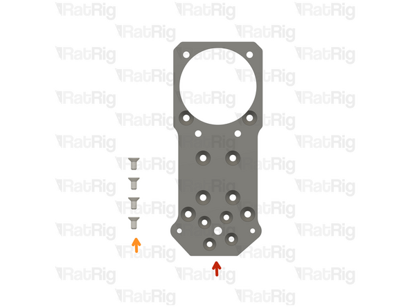
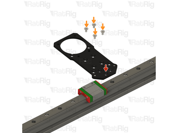
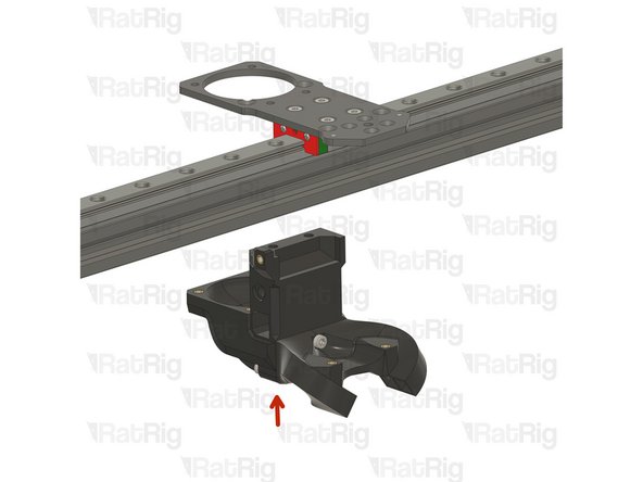
Rat Rig toolhead plate
-
4x M3x6 Countersink Screw
-
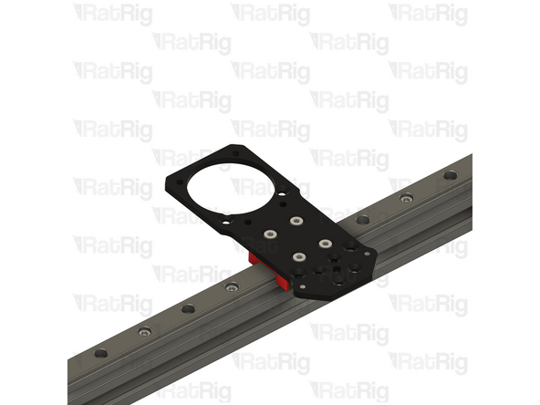
Tighten the M3x6 Countersink Screws to secure the plate to the carriage.
-
Avoid using a ball end hex key, as they are more prone to damaging the sensitive M3 countersink screw head.
-
After tightening of the screws, it is essential to verify that the X carriage retains its free movement. Excessive tightening of the screws may lead to the binding of the carriage.
-
-
-
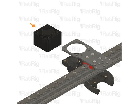
Rat Rig toolhead back assembly
-
1x 4028 Part Cooling Fan
-
2x M3x35 Countersink Screw
-
Rat Rig toolhead duct assembly
-
M3x8 Cap Head Screw
-
2x M3x16 Cap Head Screw
-
-
-
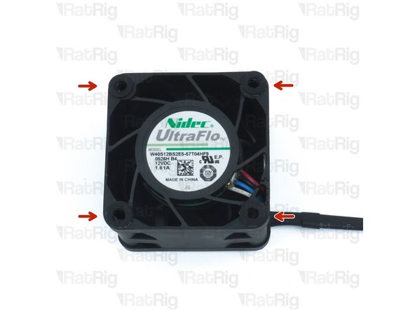
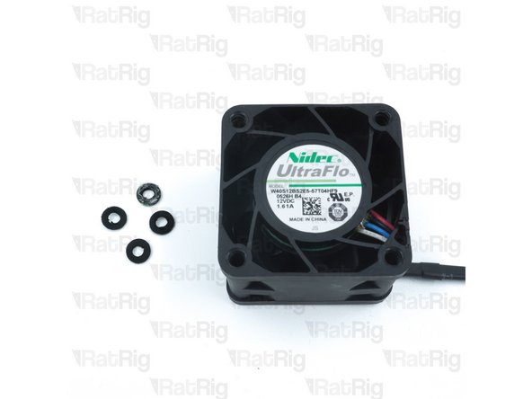
Remove the four rubber spacers on the 4028 Part Cooling Fan
-
-
-
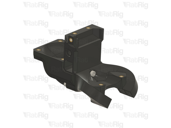
Rat Rig toolhead back assembly
-
Rat Rig toolhead duct assembly
-
2x M3x16 Cap Head Screw
-
M3x8 Cap Head Screw
-
-
-
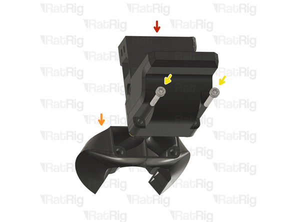
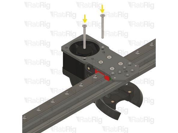
Rat Rig toolhead rear assembly from the previous step.
-
4028 Part Cooling Fan
-
2x M3x35 Countersink Screw
-
Tighten the M3x35 screws.
-
Take care not to over tighten the M3x35 screws as you can damage the printed parts
-
Avoid using a ball end hex key, as they are more prone to damaging the sensitive M3 countersink screw head.
-
-
-
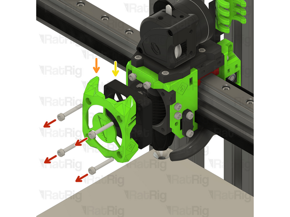
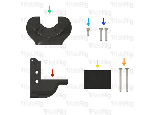
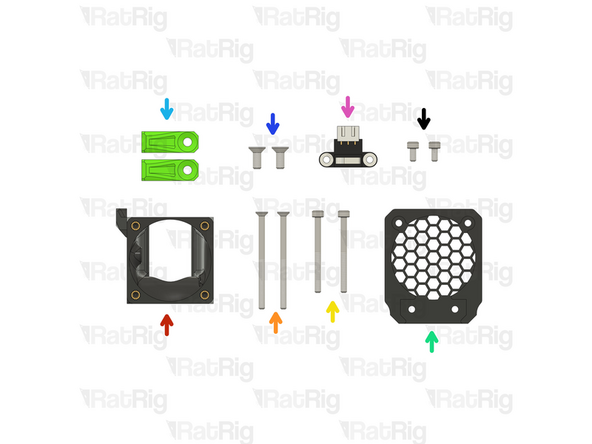
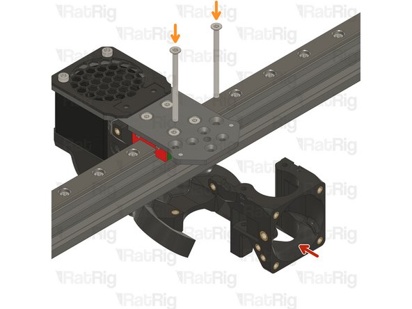
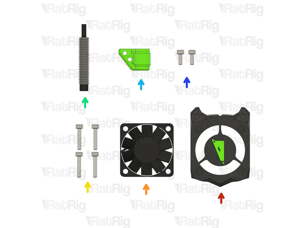
Rat Rig toolhead front assembly
-
2x M3x45 Countersink Screw
-
2x M3x35 Cap Head Screw
-
1x Rat Rig toolhead fan grille printed part
-
2x rr_vc3_toolhead_front_clamp
-
2x M4x10 Countersink Screw
-
1x X Endstop
-
2x M3x6 Cap Head Screw
-
-
-
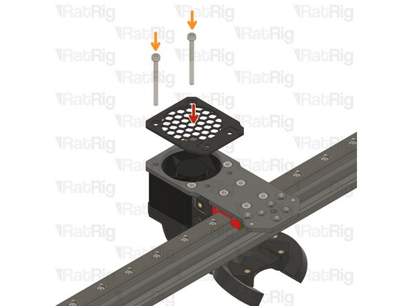
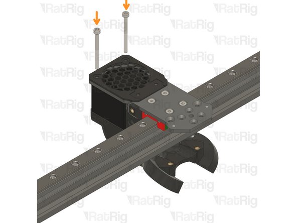
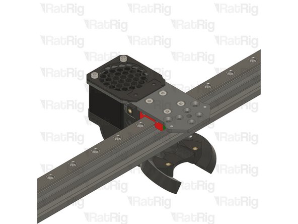
Rat Rig toolhead fan grille printed part
-
2x M3x35 Cap Head Screw
-
Feed the M3x35 cap head screws through the grille, the aluminium plate and the 4028 fan, tightening them into the back printed part.
-
Take care not to over tighten the screws as you can damage the printed parts
-
-
-
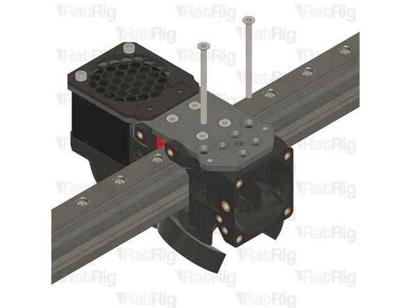
Rat Rig toolhead front printed part
-
2x M3x45 Countersink Screw
-
The M3x45 countersink screws must go through the holes on the front assembly and thread into the duct assembly.
-
Take care not to over tighten the screws as you can damage the printed parts
-
Avoid using a ball end hex key, as they are more prone to damaging the sensitive M3 countersink screw head.
-
-
-
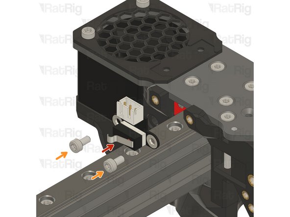
X Endstop
-
2x M3x6 Cap Head Screw
-
Tighten the M3x6 screws to secure the X endstop to the toolhead.
-
Take care not to over tighten the M3x8 screws as you can damage the printed parts.
-
-
-
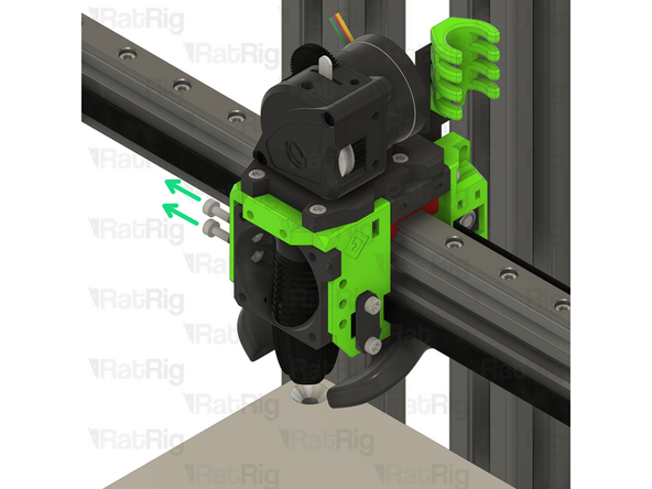
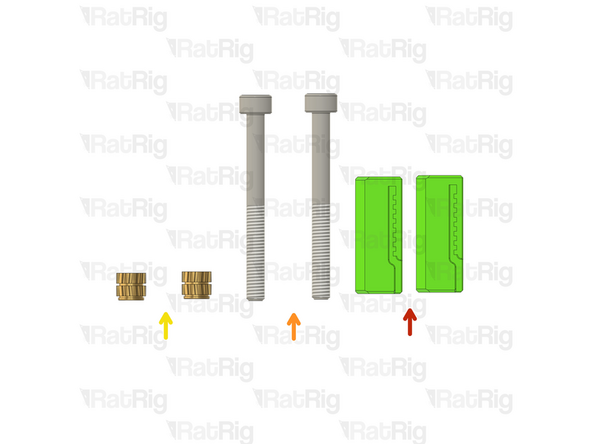
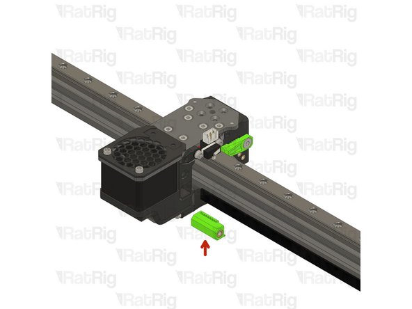
2x rr_tolhead_vc3_belt_tensioner
-
2x M4x40 Cap Head Screw
-
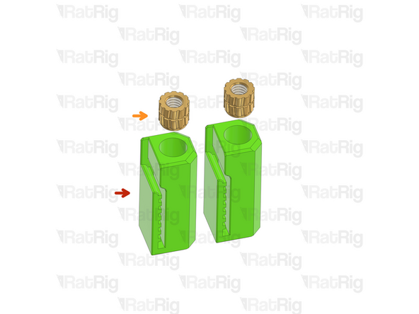
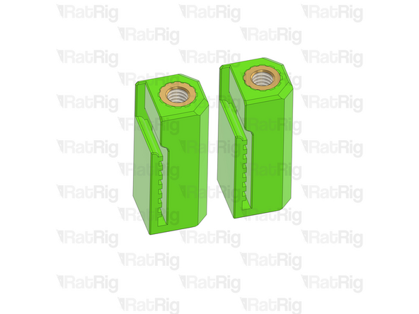
2x M4 Heat Insert
-
-
-
Make sure the belt is properly seated on all idlers and pulleys
-
rr_tolhead_vc3_belt_tensioner assembly
-
Insert the end of the belt inside the belt tensioner, and make sure the teeth are secured.
-
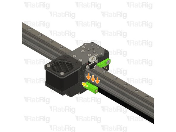
Insert the tensioner assembly into the toolhead in the shown orientation.
-
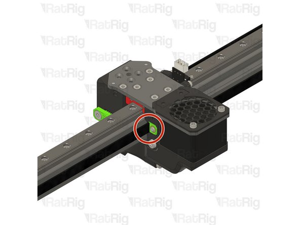
Tighten the M4x40 Cap Head just enough to hold the M4 Nylon Locking Hex Nut
-
-
-
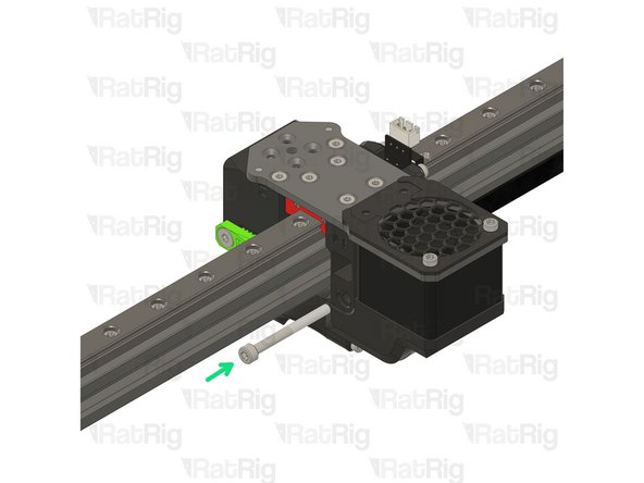
Repear Step 51 and install the top belt tensioner
-
-
-
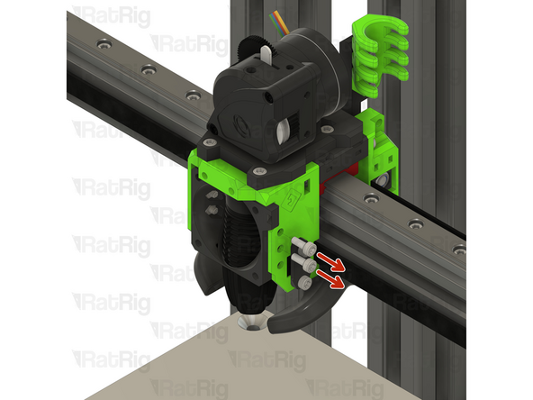
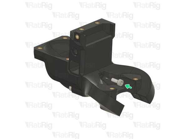
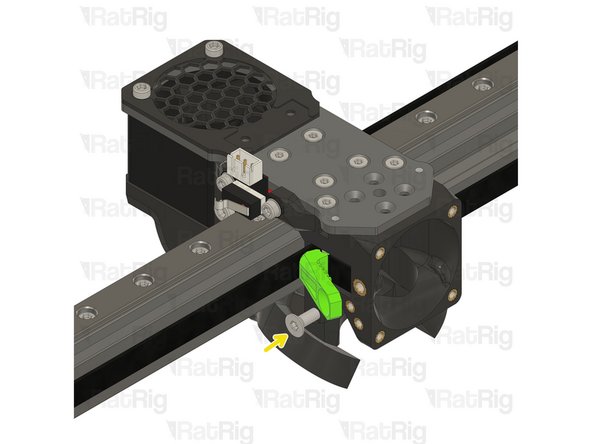
Remove the M3x40 countersink screw almost all the way.
-
Form a small loop on the belt as shown.
-
Insert the belt loop into the designated slot.
-
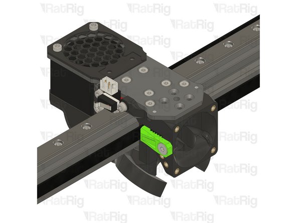
Tighten the M3x40 countersink screw and make sure the belt goes around it, as shown in the picture.
-
Pull all the excess belt.
-
Cut the excess belt, ensuring the total length is enough to press it against the indent.
-
-
-
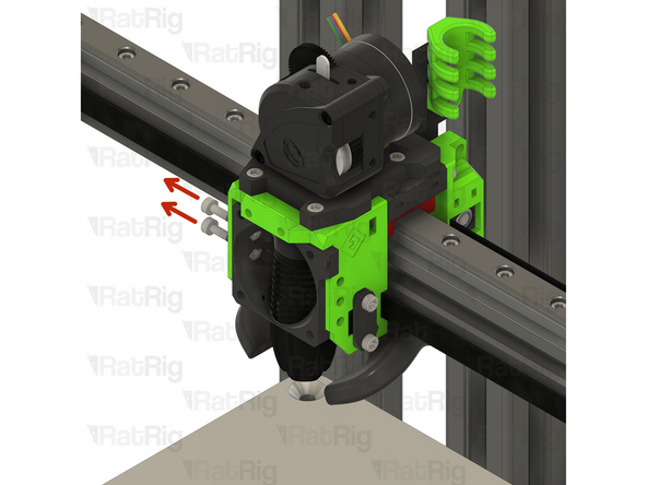
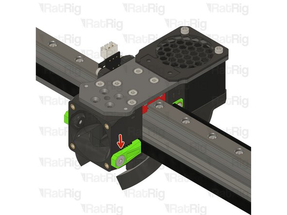
Rat Rig toolhead front belt clamp
-
Lever the belt clamp against the exposed screw section and place it inside the belt slot.
-
1x M4x10 Countersink Screw
-
Tighten the M4x10 screw making sure the teeth of the belt clamp mesh with the belt
-
Pay attention to seating the notch on the belt clamp on the exposed screw section. Pull on the belt to make sure it's secured properly.
-
-
-
Repeat Steps 53 and 54 to attach the other belt
-
-
-
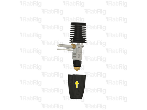
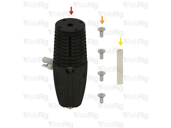
Phaetus Rapido V2 UHF Hotend
-
4x M2.5x6 Countersink Screw
-
PTFE tube - 24.5mm
-
-
-
Phaetus Rapido V2 UHF
-
Place the Phaetus Rapido V2 UHF Hotend on the plate, making sure to route the cables through the designated slot
-
4x M2.5x6 Countersink Screw
-
Tighten the M2.5x6 Countersink Screws to secure the hotend to the plate.
-
Avoid using a ball end hex key, as they are more prone to damaging the sensitive M2.5 countersink screw head.
-
PTFE tube - 24.5mm
-
Insert the PTFE tube in to the marked hole and push it until it stops.
-
-
-
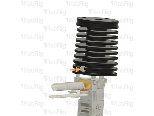
Rat Rig toolhead_shourd printed part
-
140x10mm 24V Axial Fan
-
4x M3x16 Cap Head Screw
-
Rat Rig SuperPinda Probe by P&F
-
rr_tolhead_vc3_probe_mount
-
2x M3x8 Cap Head Screws
-
-
-
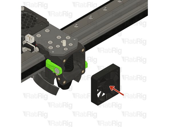
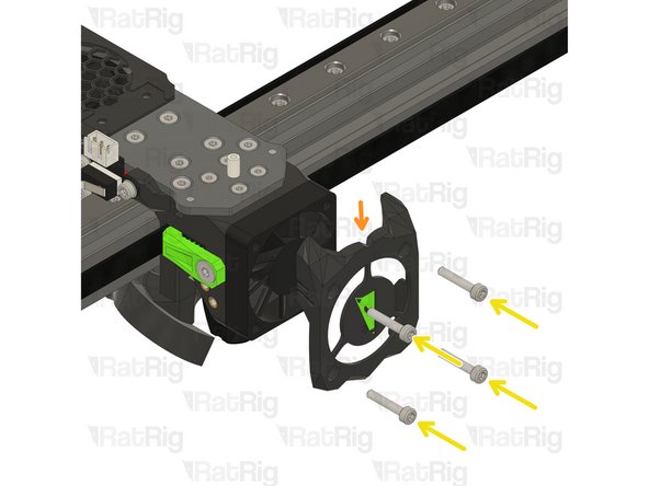
40x10mm 24V Axial Fan
-
rr_toolhead_vc3_shroud printed part
-
4x M3x16 Cap Head Screw
-
Insert the M3x16 screws into the Rat Rig toolhead shroud printed part, through the 40mm fan, and fasten them into the Rat Rig toolhead front
-
Pay special attention to the fan airflow, it should blow the air towards the hot end heat sink. Most fans have a small arrow indicating the airflow.
-
-
-
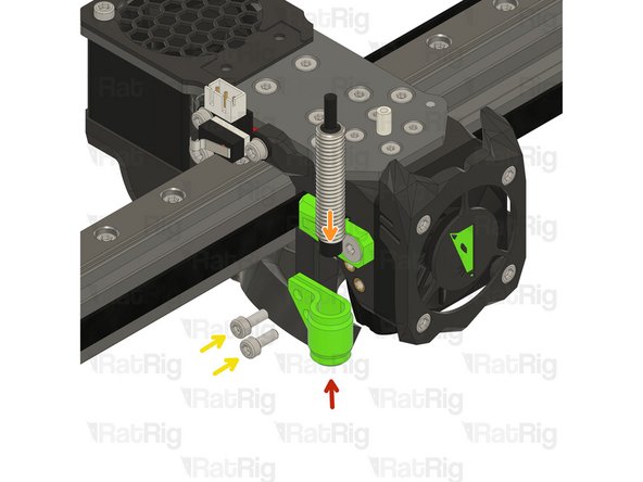
rr_tolhead_vc3_probe_mount
-
Rat Rig SuperPinda Probe by P&F
-
Insert the super pinda in the probe_mount
-
2x M3x8 Cap Head Screws
-
thread the M3x8 screws to hold the assembly. Do not tighten them yet!
-
Adjust the probe up to down as necessary to position the tip 1mm higher than the hot end nozzle
-
Tighten the M3x8 Cap Head screws to secure the probe in place
-
Do not over-tighten the screws, doing so can damage the probe or printed probe mount
-
-
-
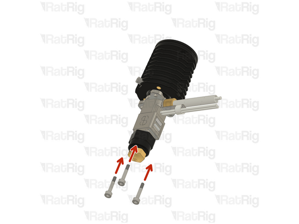
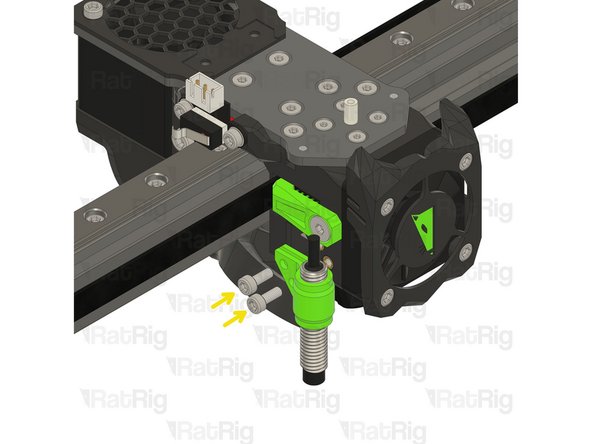
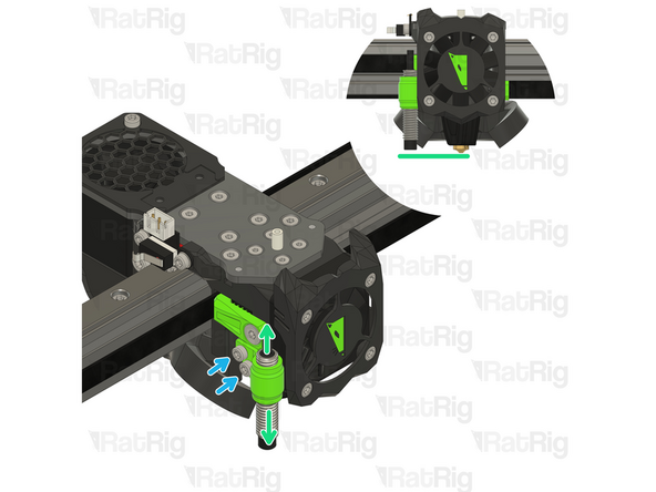
LDO Orbiter V2
-
2x M3x8 Cap Head Screw
-
Carefully align the extruder with the PTFE tube.
-
Insert the M3x8 screws into the LDO Orbiter V2 and fasten them to the Rat Rig toolhead plate.
-
Take care not to over tighten the M3x8 screws as you can strip the toolhead plate threads
-
-
-
If you are assembling a toolboard, skip to Step 66
-
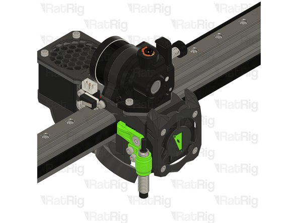
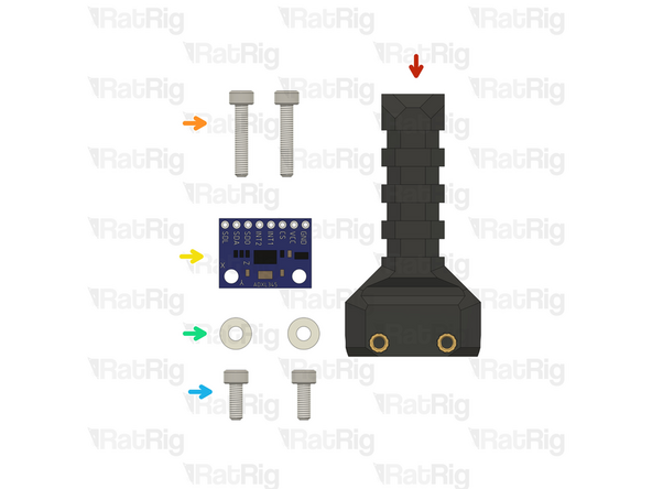
Rat Rig toolhead umbilical assembly
-
2x M3x16 Cap Head Screw
-
ADXL 345 Accelerometer
-
2x M3 Nylon washer
-
2x M3x8 Cap Head Screw
-
-
-
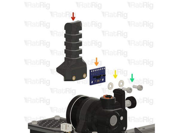
Rat Rig toolhead umbilical assembly
-
ADXL 345 Accelerometer
-
1x M3 Nylon washer
-
2x M3x8 Cap Head Screw
-
Take care not to over tighten the M3x8 screws as you can damage the ADXL
-
-
-
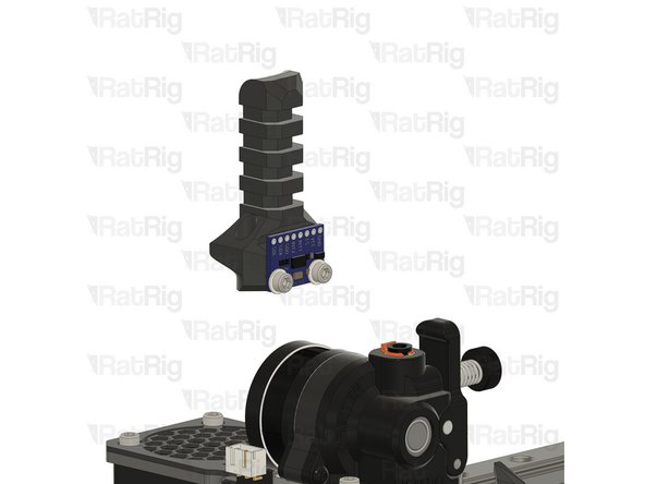
Rat Rig toolhead umbilical assembly
-
2x M3x16 Cap Head Screw
-
Tighten the M3x16 screws to secure the umbilical assembly to the plate.
-
Take care not to over tighten the M3x16 screws as you can damage the printed parts
-
-
-
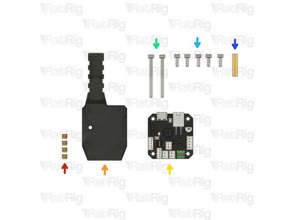
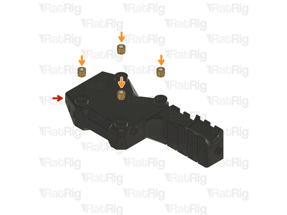
4x Heat insert M3
-
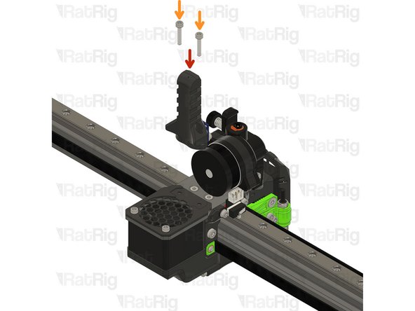
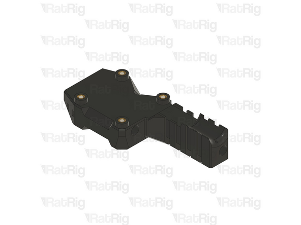
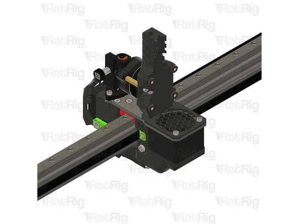
rr_toolhead_vc3_ebb42_vertical printed part
-
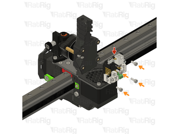
BIGTREETECH EBB42 USB/CAN TOOLBOARD V1.2
-
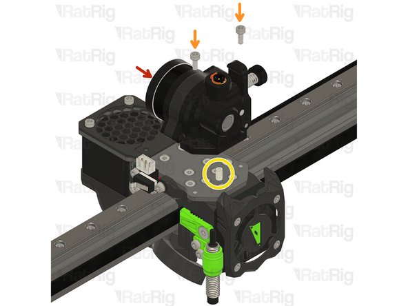
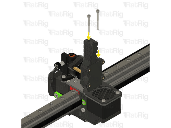
2x M3x35 Cap Head Screw
-
5x M3x8 Cap Head Screw
-
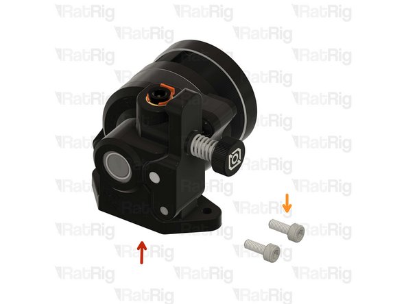
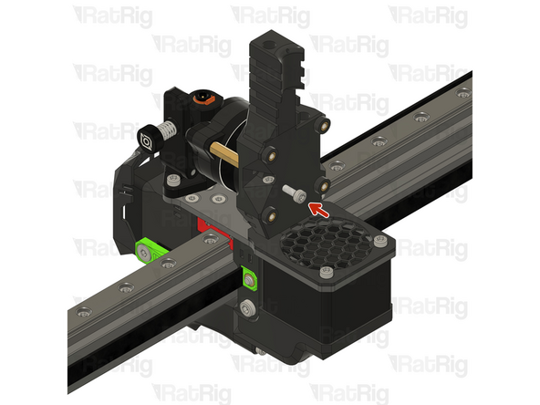
Hex standoff brass M3x20x4.5
-
-
-
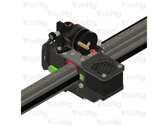
Thread the hex standoff on to the LDO Orbiter V2 screws.
-
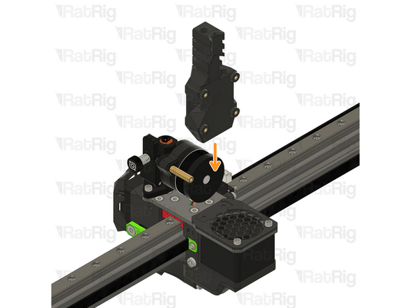
Place the Rat Rig toolhead_vc3_ebb42_vertical assembly as shown
-
Insert the M3x35 Cap Head Screws in to the printed part and thread them to the toolhead plate.
-
-
-
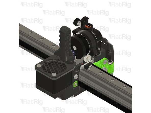
M3x8 Cap Head Screw
-
Insert the M3x8 Cap Head Scres in to the printed part and thread them to the hex standoff
-
Take care not to over tighten the M3x8 screw as you can damage the printed parts
-
-
-
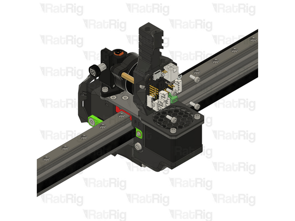
BIGTREETECH EBB42 USB/CAN TOOLBOARD V1.2
-
Insert the M3x8 Cap Head Screws into the toolboard and thread them into the vertical toolboard mount
-
Take care not to over tighten the M3x8 screws as you can damage the printed parts and the toolboard
-
-
-
Click here to follow the V-Core 3.1 Wiring guide and finish all the toolhead connections.
-
If you are using a toolboard: Please note that the toolboard is not part of the standard configuration for the V-Core 3.1. However, you may find the V-Core 4 wiring guide helpful for reference. Keep in mind that there are differences between the two models, so the wiring guide should not be considered a direct, one-to-one comparison.
-