
-
-
Phaetus Rapido V2 UHF Hotend
-
Cut the wires with 150mm and strip 5-10mm of the end, to expose the inside conductor.
-
Cut the thermistor wires with 160mm and crimp a JST 2 connector
-
The thermistor is a resistor that strongly varies with temperature. When crimping a resistor you don't have to worry about wire order as resistors don't have polarity.
-
-
-
Hot End Heater 24V
-
Insert the cable ends on the designated slots and tighten the screws.
-
After tightening the screws, pull the cable to make sure it's firmly connected. If the cable releases/moves when pulling, reinsert it and tighten the screw.
-
Hot End Thermistor
-
Plug the connector into the designated connector.
-
The thermistor wires are very fragile, bending them past its threshold can damage the conductors within, leading to wire failure.
-
Insert the highlighted jumper to achieve more accurate temperature readings
-
Route the wires accordingly.
-
-
-
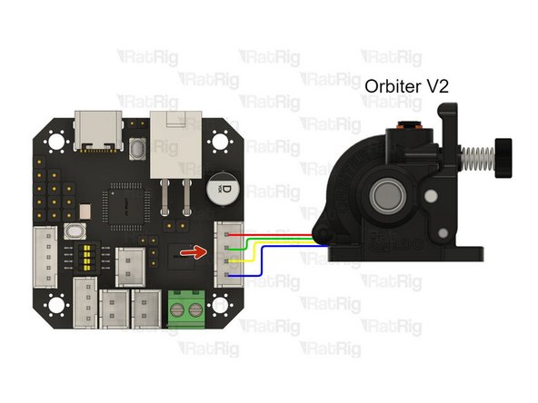
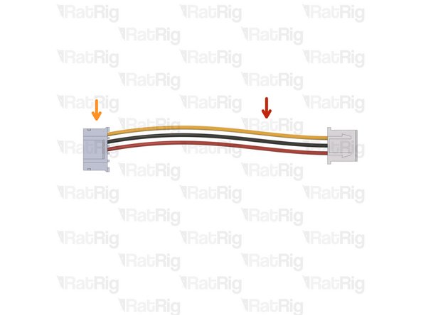
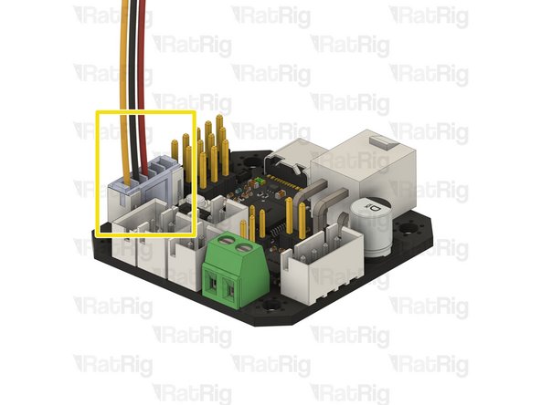
Connect the orbiter extruder cable to the designated slot on the toolboard
-
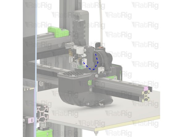
Route the wires accordingly.
-
-
-
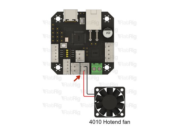
Hot End 4010 fan - 24V
-
Connect the positive and negative wires to the referred slot.
-
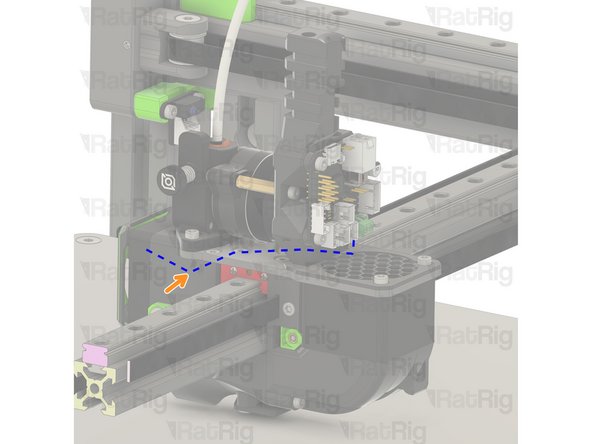
Route the cable accordingly.
-
Use a zip tie to ensure the cable is secure to the toolhead body.
-
-
-
Cable 120mm - 3 Conductor 24AWG - JST XH2.54 male to Bare wire
-
Micro JST 5pins provided with the EBB42 Toolboard package
-
Crimp the connector on the 3 wires as shown.
-
Refer to this picture to clearly show where the wires go
-
-
-
Warning: Check your cables. Incorrect endstop wiring can damage your board.
-
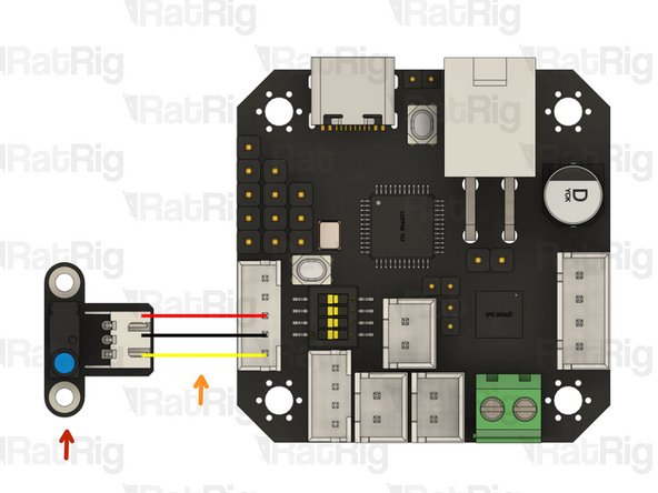
Rat Rig Omron X endstop
-
Endstop 3 wire cable - Prepared previously.
-
Connect the JST3 connector to the shown slot on the toolboard.
-
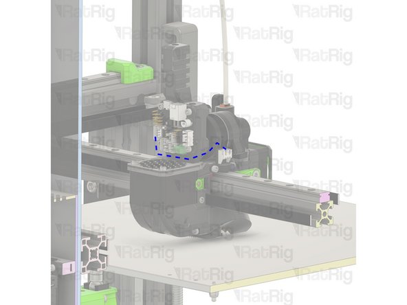
Route the cable accordingly.
-
-
-
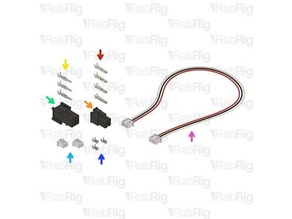
4x Crimp - Molex Micro-Fit (43025 compatible)
-
Connector - Molex Micro-Fit - 4 Pin - Male (43025-0400)
-
3x Crimp - Molex Micro-Fit (43020 compatible)
-
Connector - Molex Micro-Fit - 4 Pin - Female (43020-0400)
-
2x Connector - 2 Pin - JST XHP-2 - 2.54 Male
-
4x Crimp - JST XH 2.54
-
Cable 1500mm - 3 Conductor 24AWG - JST XH2.54 to JST XH2.54
-
-
-
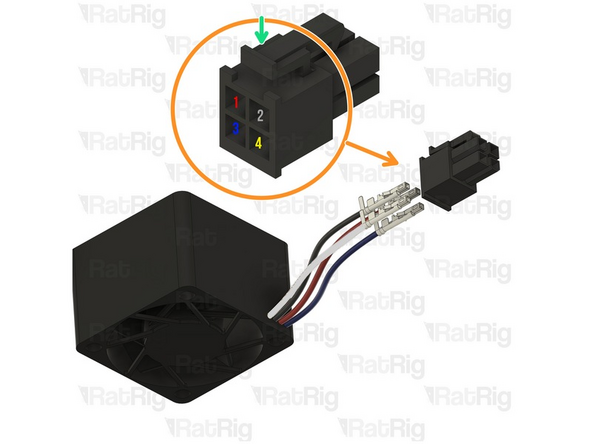
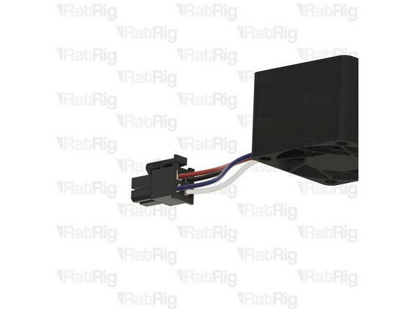
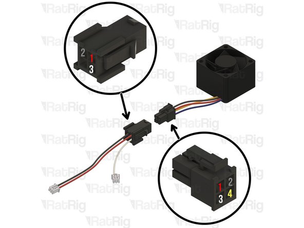
Crimp the Connector - Molex Micro-Fit (43025 compatible) to all the 4028 wires
-
The small tab must be facing upwards.
-
Insert the crimps inside the Connector - Molex Micro-Fit - 4 Pin - Male (43025-0400) as shown
-
1 - 12V Red - NIDEC fan
-
2- GND Black - NIDEC fan
-
3- PWM Blue - NIDEC fan
-
4- Tac White -NIDEC fan (not used with the Octopus board(
-
Insert the crimp on the connector until you hear a "Click"
-
-
-
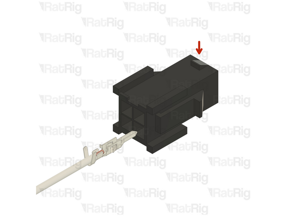
Cut the JST3 connectors on the Endstop cable and crimp the Molex Micro-Fit (43020 compatible)
-
Insert them into the Connector - Molex Micro-Fit - 4 Pin - Female (43020-0400) as shown on the images
-
The small lock piece on the connector must be facing upwards.
-
-
-
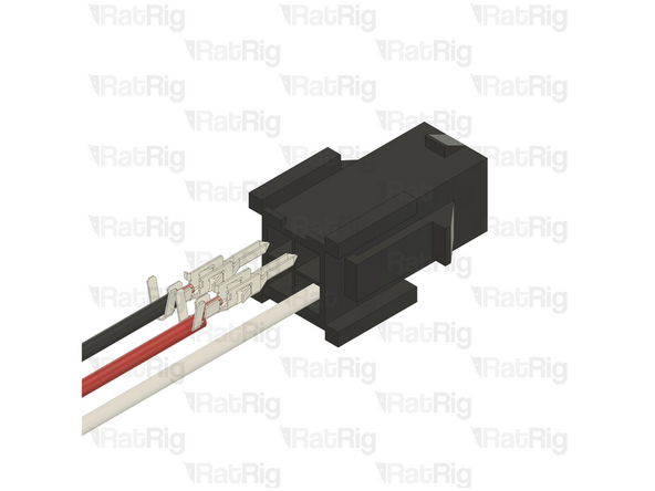
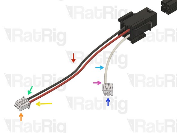
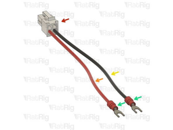
Use the full length of the RED and Black wires
-
2 Pin - JST XHP-2 - 2.54 Male
-
Crimp the GND (Black) wire to the left slot on the housing
-
Crimp the +12V (RED) wire to the left slot on the housing
-
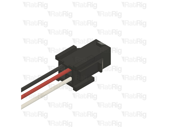
Cut the white wire with 70mm, measuring from the Molex connector
-
2 Pin - JST XHP-2 - 2.54 Male
-
Crimp the PWM (White) wire to the left slot on the housing
-
Triple check all connections and crimps
-
-
-
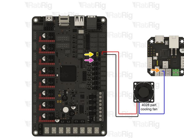
Cooling 4028 fan - 12 V
-
Connect the PWM wire to the negative pin (the one closest to the middle of the toolboard) of the shown connector.
-
Connect the positive and negative wire to the referred slot where the 12V jumper was placed.
-
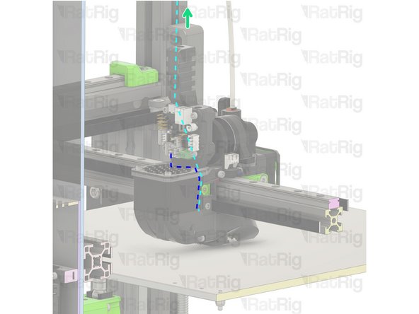
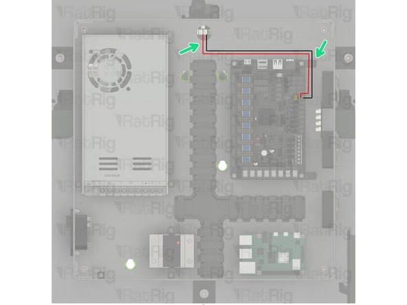
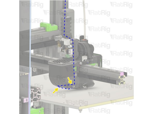
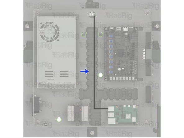
Route the power cable back to the electronics enclosure and follow the piano wire previously installed.
-
Use some zip ties to clean the excess cable inside the electronics enclosure.
-
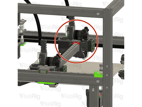
Route the PWM wire as shown.
-
IDEX ONLY Connect the 4028 cooling fan from T1 on the slot below. Ensure the jumper is set to 12V.
-
-
-
The power connector provided in the EBB42 toolboard box
-
Carefully check the wire order, if the polarity is swapped, you will destroy your electronics!
-
Crimp the red and black wires on the connector as shown
-
Wire - DC Power - 18AWG RED - 1000mm
-
Wire - DC Power - 18AWG BLACK - 1000mm
-
2x Fork Terminal - 3.7mm Insulated
-
Crimp the fork connectors as shown
-
-
-
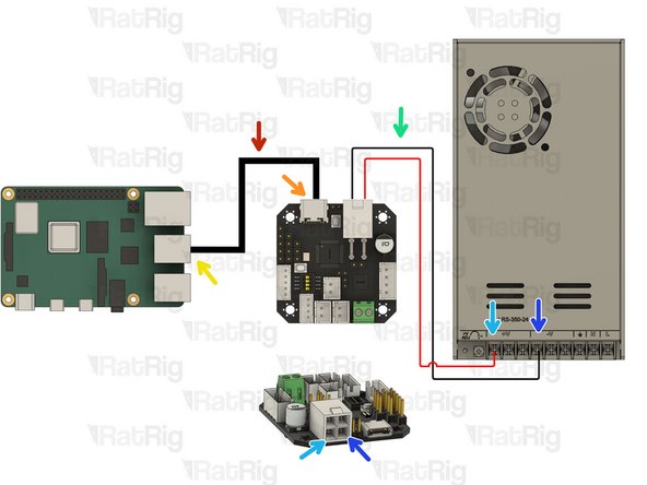
Cable - USB-A to USB-C Cable 1500mm
-
Connect the USB C port on the toolboard
-
Connect the USB A Port on the Raspberry Pi
-
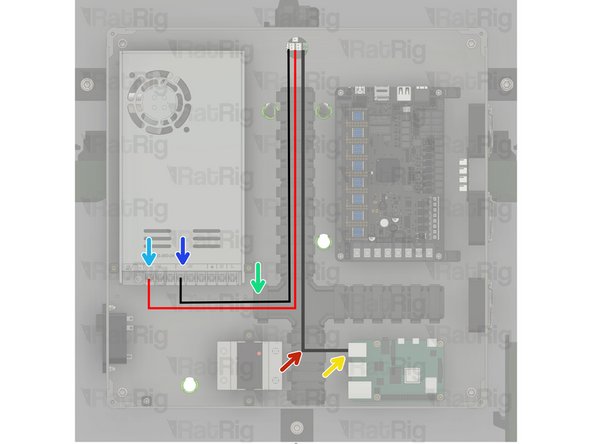
Red and Black Power wires
-
Red Wire- Power Input +24V on the Toolboard and [+V] on the Power Supply
-
Black Wire- Power Input GND on the Toolboard and [-V] on the Power Supply
-
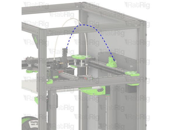
Route the cables back to the electronics enclosure and follow the piano wire previously installed - Use some zip ties to clean the excess cable inside the electronics enclosure.
-
It is imperative to make sure that the USB-C connector cannot move! Tie it down to the printed part using some zip ties.
-
-
-
Ignore this Step if you are wiring the IDEX T1 toolhead
-
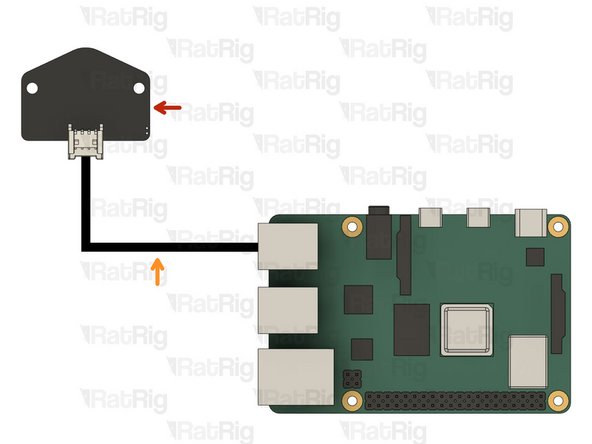
Beacon Z probe
-
USB Beacon cable
-
Connect the cable to the beacon and the Raspberry Pi
-
Use two zip ties to ensure the cable is secure to the toolhead body.
-
Route the cables back to the electronics enclosure and follow the piano wire previously installed.
-
Use some zip ties to clean the excess cable inside the electronics enclosure.
-
Have we mentioned how good the Beacon probe is? Just wait until you fire it up, you can find more info here.
-
-
-
Repeat Steps 1 to 13 to complete the wiring of the second toolhead.
-


Cancel: I did not complete this guide.
One other person completed this guide.
