-
-
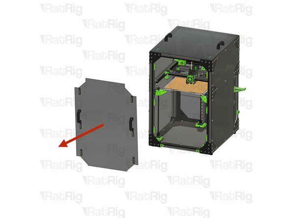
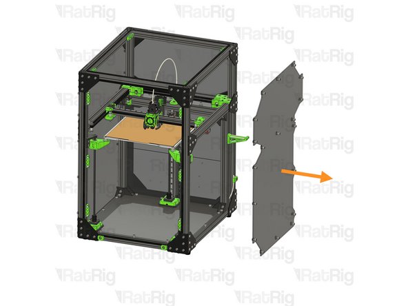
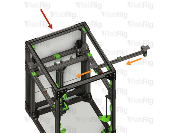
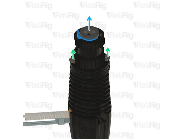
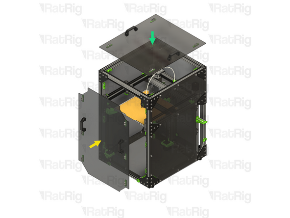
Remove the front door
-
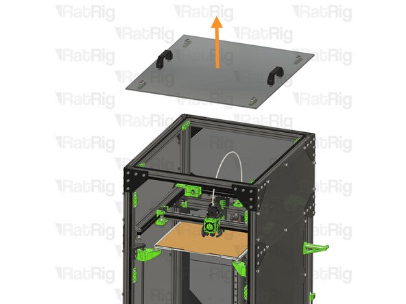
Remove the lid
-
Set both the front door and lid aside until the upgrade is complete
-
-
-
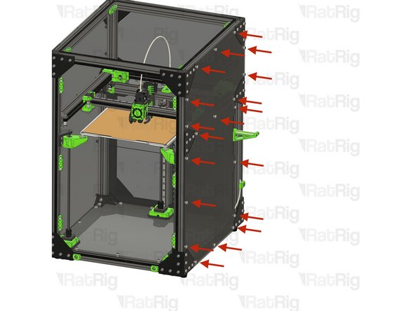
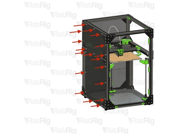
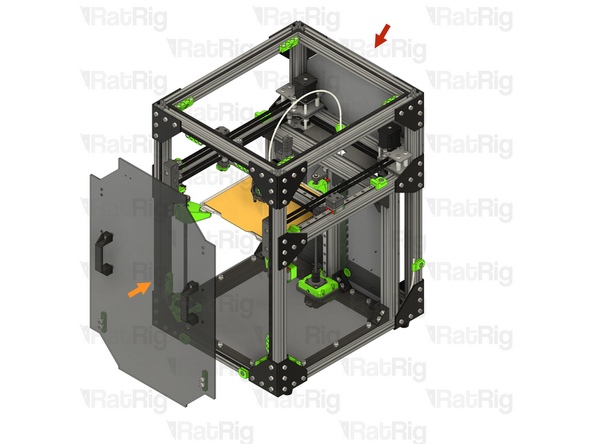
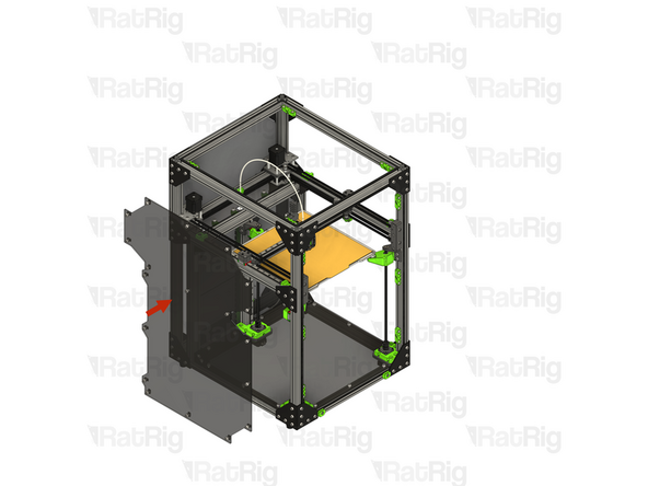
Loosen all of the M6 Cap Head Screws securing the right enclosure panel
-
It may take some slight wiggling of the M6 Cap Head Screws to allow the 3030 T-nuts to come free from the extrusion slot
-
Remove the right side enclosure panel
-
Set the enclosure panel aside until the upgrade is complete
-
-
-
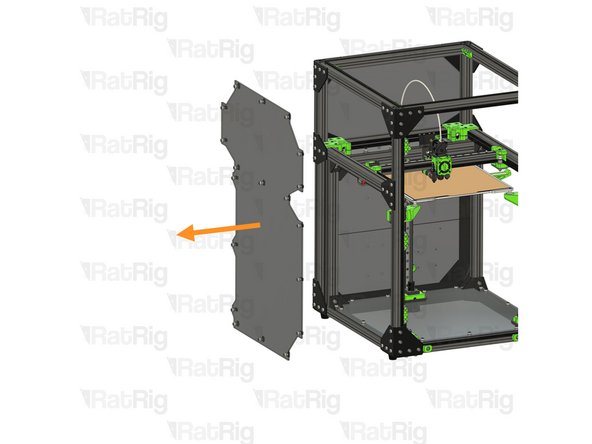
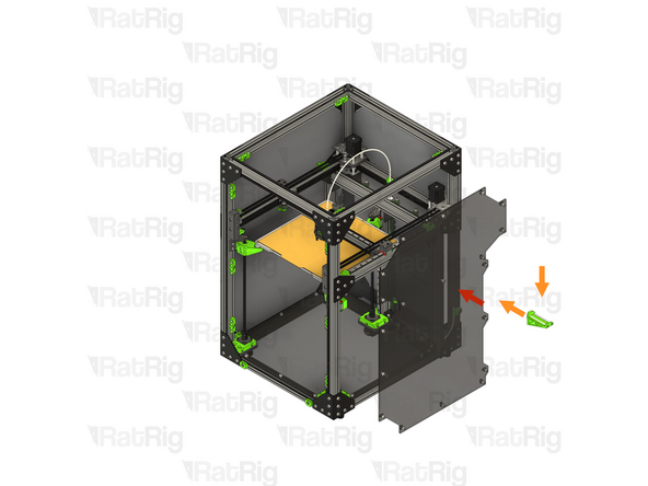
Loosen all of the M6 Cap Head Screws securing the left enclosure panel
-
It may take some slight wiggling of the M6 Cap Head Screws to allow the 3030 T-nuts to come free from the extrusion slot
-
Remove the left side enclosure panel
-
Set the enclosure panel aside until the upgrade is complete
-
-
-
Make sure the V-Core 3.1 is unplugged from AC power before proceeding
-
-
-
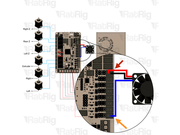
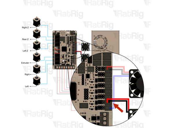
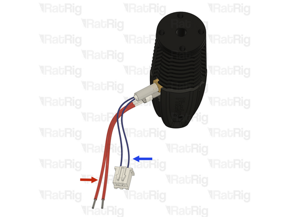
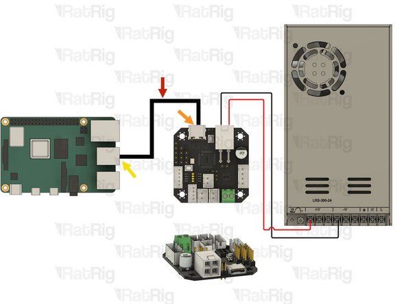
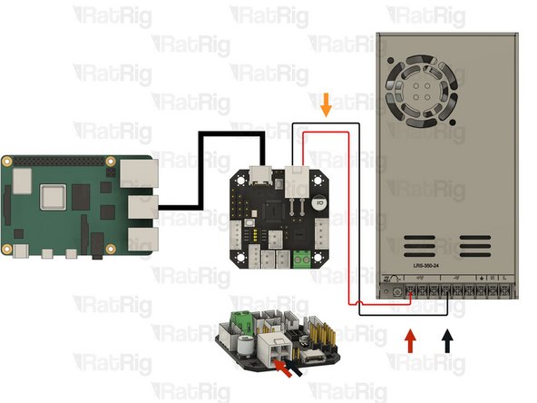
Remove the 12V power connection from the Octopus motherboard
-
Remove the PWM connection from the Octopus motherboard
-
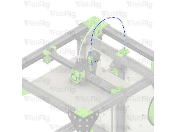
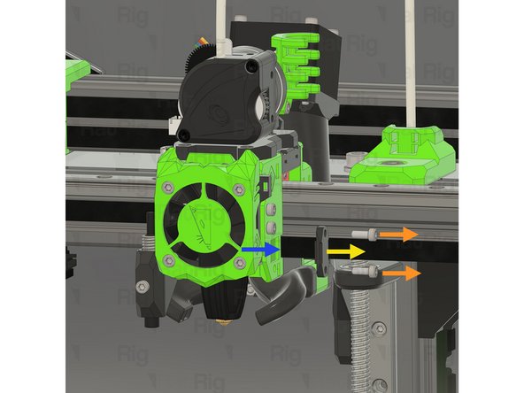
Remove the part cooling fan wiring from the rear of the machine, back to the toolhead
-
-
-
Remove the 12V power connection from the Octopus motherboard
-
Remove the hotend fan wiring from the rear of the machine, back to the toolhead
-
-
-
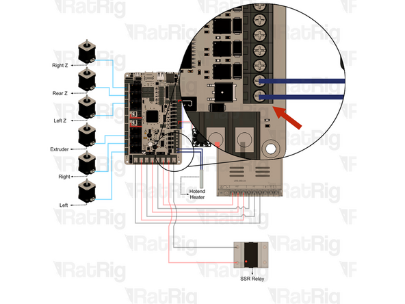
Loosen the two screws on the terminal and pull out the hotend heater wiring from the Octopus motherboard
-
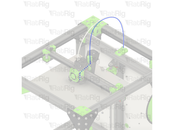
Remove the hotend heater wiring from the rear of the machine, back to the toolhead
-
-
-
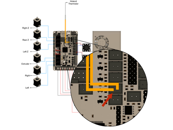
Remove the hotend thermistor connection from the Octopus motherboard
-
Remove the hotend thermistor wiring from the rear of the machine, back to the toolhead
-
-
-
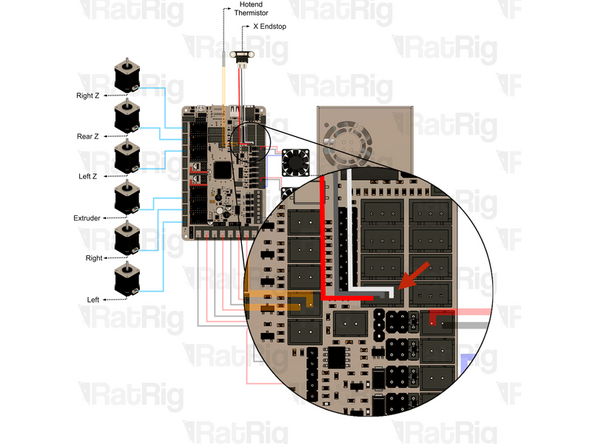
Remove the X-axis endstop connection from the Octopus motherboard
-
Remove the X-axis endstop wiring from the rear of the machine, back to the toolhead
-
-
-
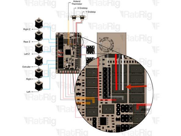
Remove the Y-axis endstop connection from the Octopus motherboard
-
Remove the Y-axis endstop wiring from the rear of the machine, back to the Y-axis endstop
-
Disconnect the Y-axis endstop wiring from the Y-axis endstop
-
-
-
Remove the Z-probe connection from the Octopus motherboard
-
Remove the Z-probe wiring from the rear of the machine, back to the toolhead
-
-
-
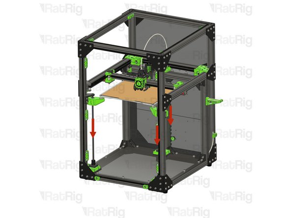
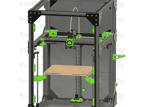
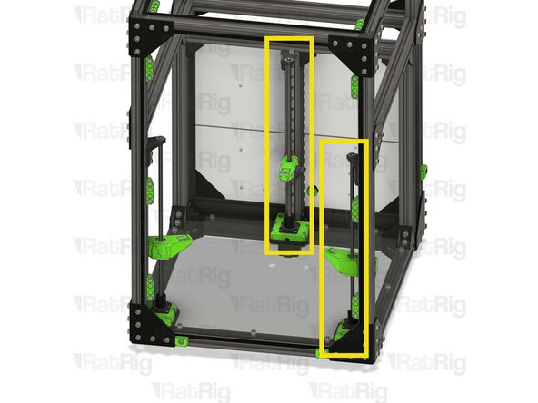
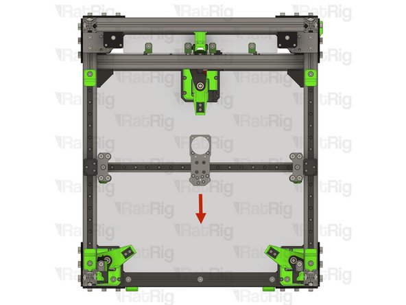
Slowly rotate each of the three Z-axis lead screws, counter clockwise, to lower Z-axis away from the toolhead
-
-
-
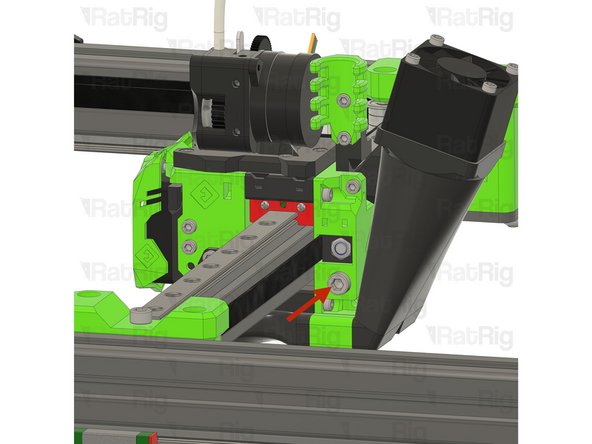
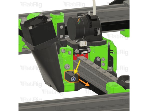
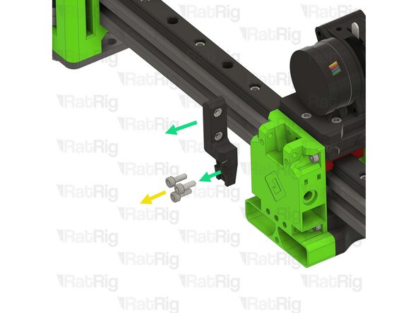
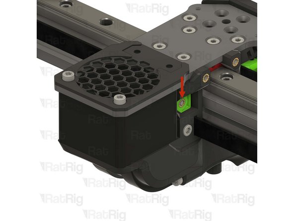
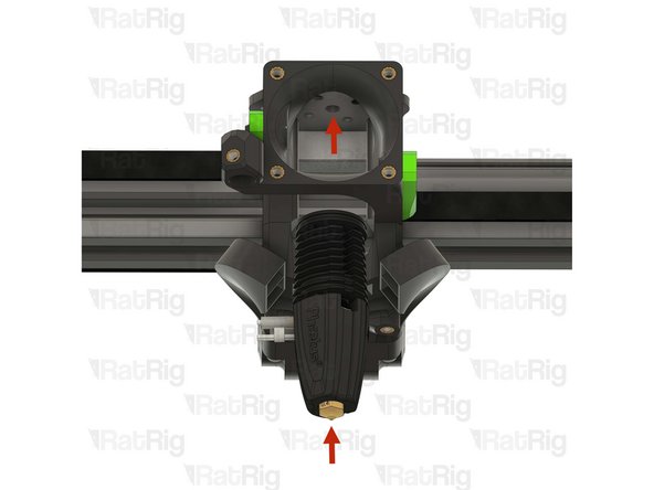
Unscrew and remove the marked M5x40 Cap Head Screw
-
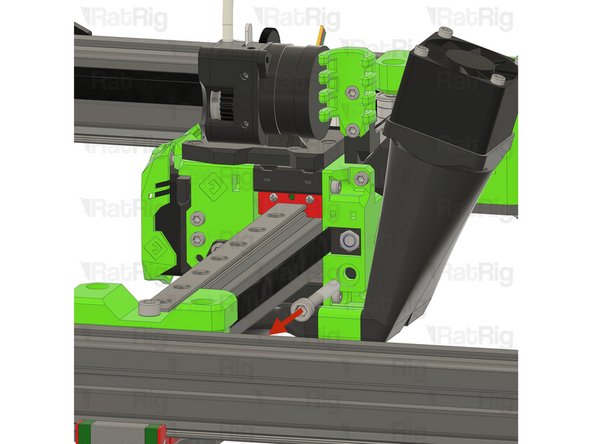
Gently pull the belt to remove the EVA core_xy_belt_grabber from the toolhead
-
Remove the belt from the slot in the EVA core_xy_belt_grabber
-
-
-
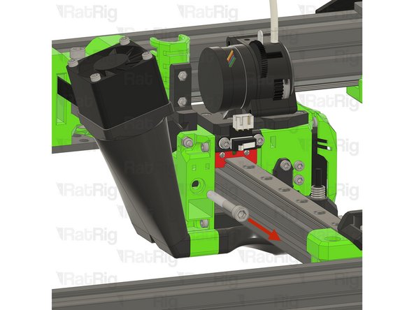
Unscrew and remove the marked M5x40 Cap Head Screw
-
Gently pull the belt to remove the EVA core_xy_belt_grabber from the toolhead
-
Remove the belt from the slot in the EVA core_xy_belt_grabber
-
-
-
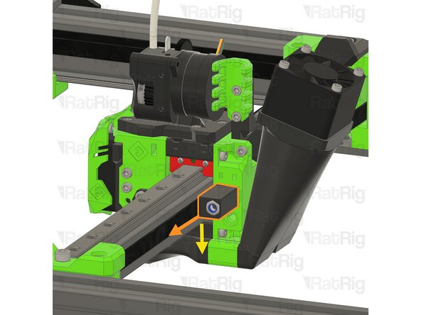
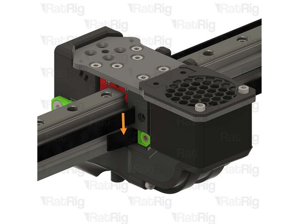
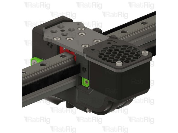
Remove the right side belt:
-
Remove both M3x8 Cap Head Screws
-
Remove the EVA face_belt_grabber
-
Remove the belt from the slot on the toolhead
-
Repeat the steps above to remove the left side belt
-
-
-
Slowly pull one end of the CoreXY belt to remove it fully from the machine
-
Repeat to remove the second CoreXY belt
-
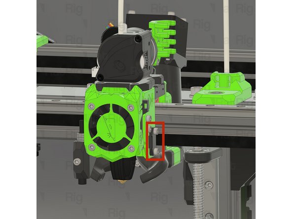
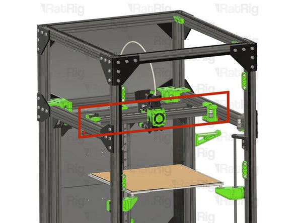
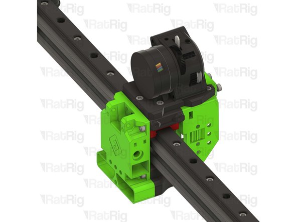
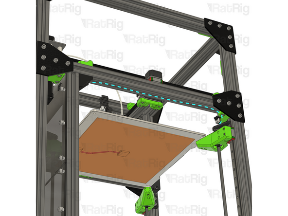
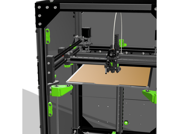
It is important that the X-axis gantry is fully supported until completely removed. Do not let it fall or hang unsupported from one side. Support it with one hand whilst removing the screws.
-
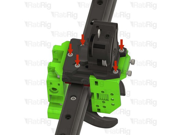
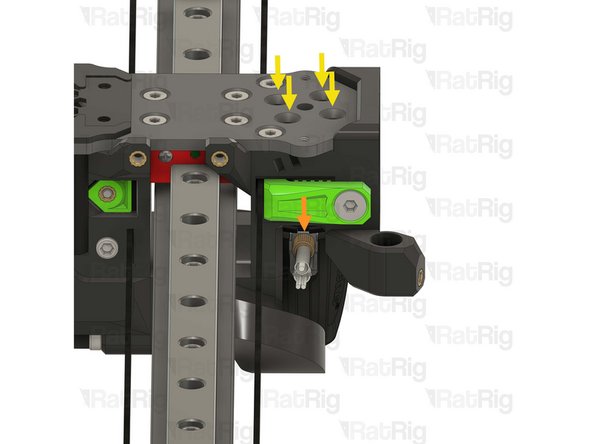
Remove the four M3x8 Cap Head Screws holding the X-axis gantry to the left Y-axis linear rail carriage
-
Continue supporting the X-axis gantry until the next step is complete
-
-
-
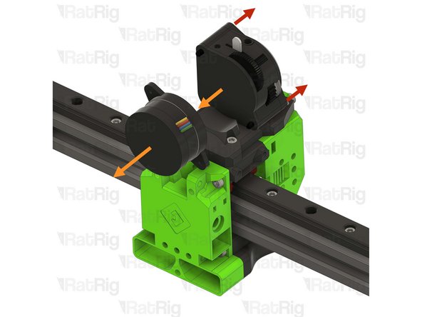
Remove the four M3x8 Cap Head Screws holding the X-axis gantry to the right Y-axis linear rail carriage
-
The X-axis gantry assembly should now be free. Lower it gently and rest it on the bed
-
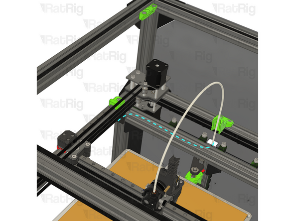
Check that all of the toolhead wiring is disconnected and free, and remove the PTFE tube from the extruder
-
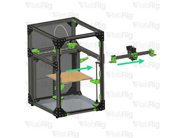
Remove the X-axis gantry assembly from the machine frame, either through the side or the front
-
-
-
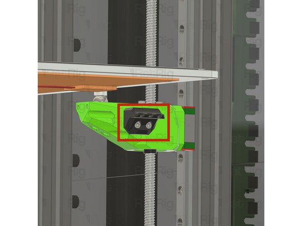
Before proceeding, take note of where the bed heater is connected. This will be needed when reinstalling the bed assembly later in the guide. Taking a photo would be wise
-
Disconnect the heated bed thermistor from the Octopus mainboard, as well as the AC connections from the PSU and SSR
-
Feed the bed wiring back through the rear panel
-
Remove the zip ties securing the bed wiring to the rear Z-axis arm
-
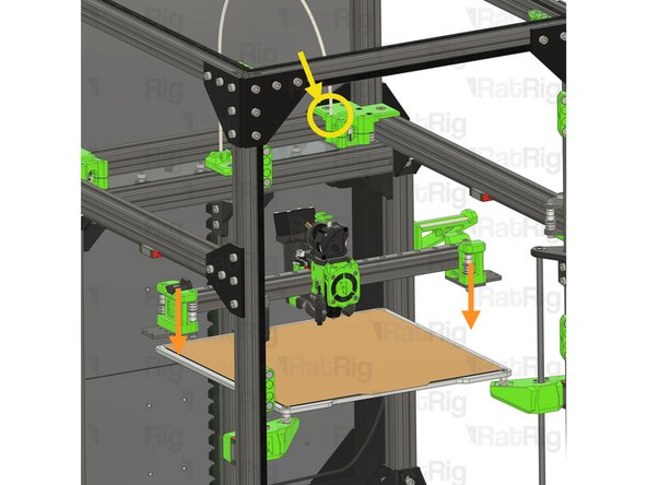
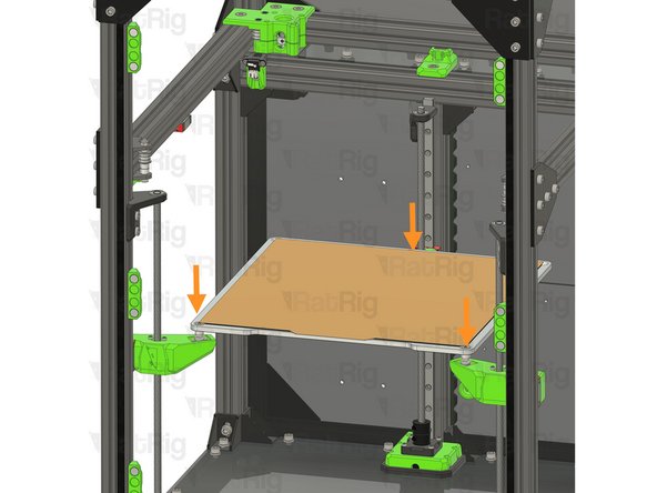
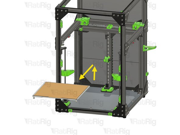
Lift the bed assembly upwards from the Z-axis arms
-
Carefully remove the bed assemble from the machine and store it somewhere safe
-
-
-
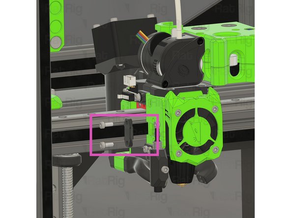
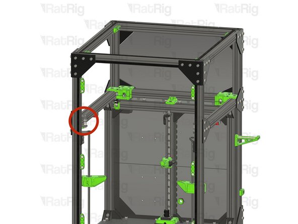
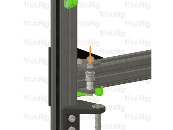
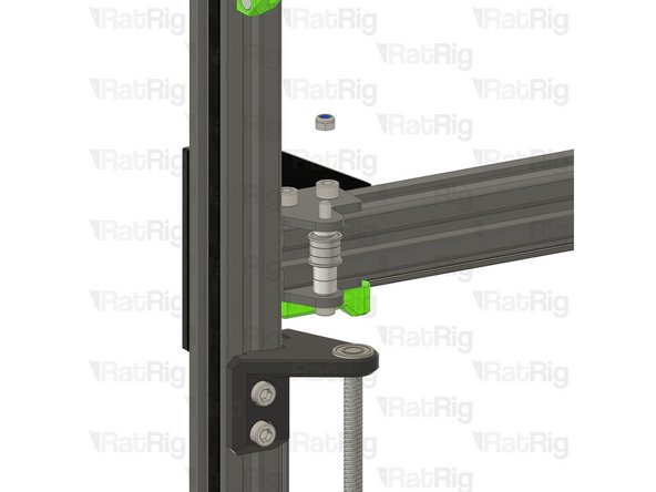
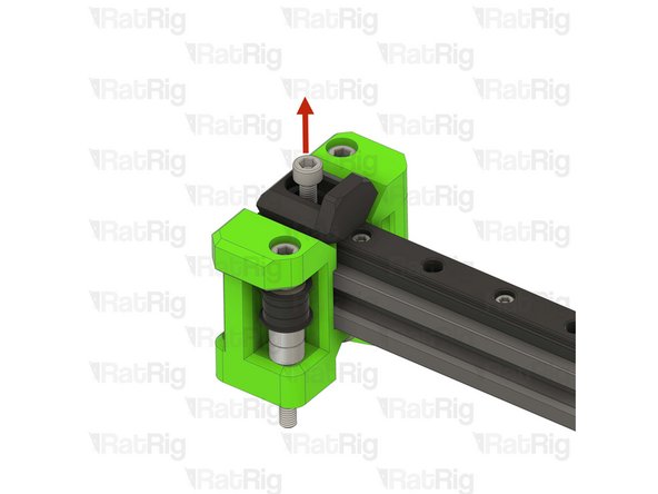
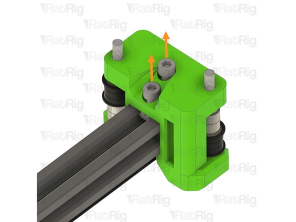
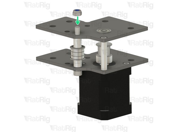
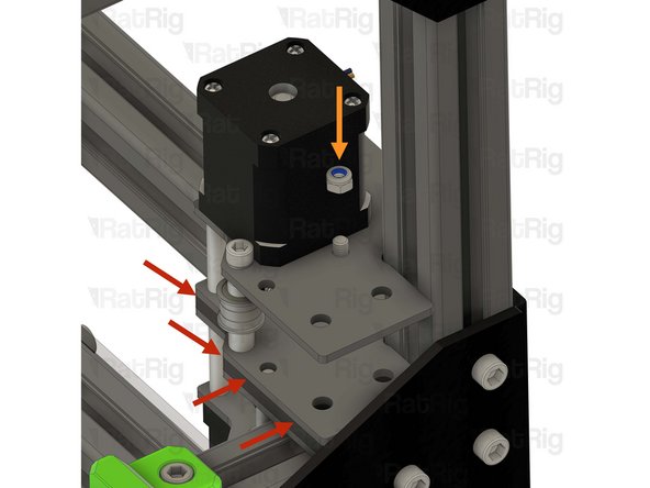
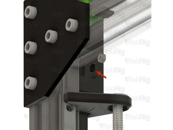
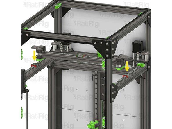
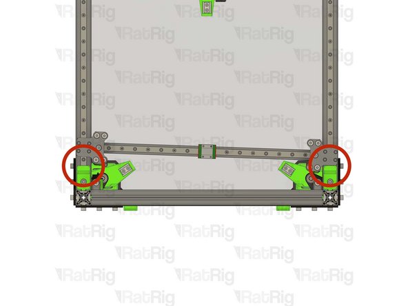
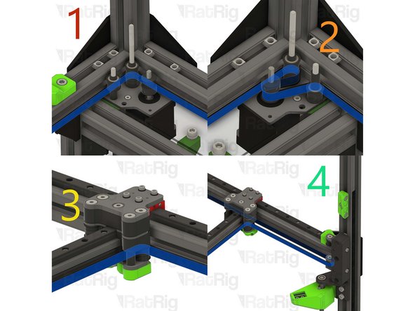
This step, and the next two steps, detail removing the front left idler assembly
-
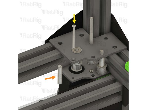
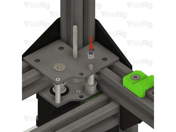
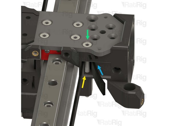
Unscrew, and remove, the top M5 nylon locking nut
-
-
-
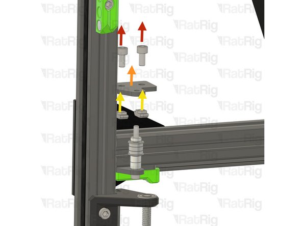
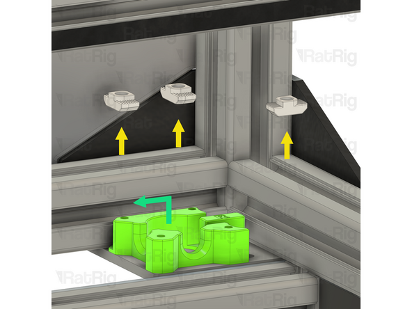
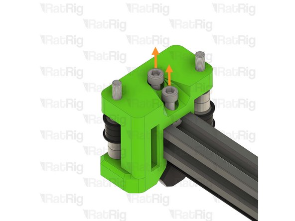
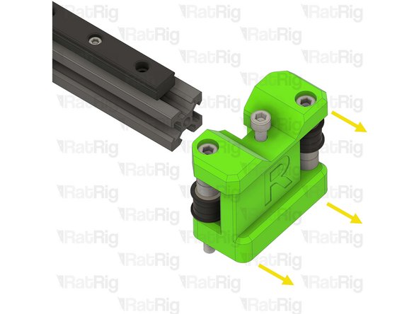
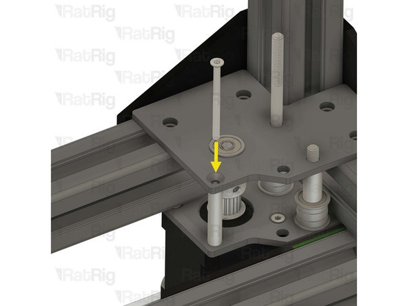
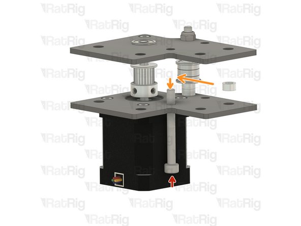
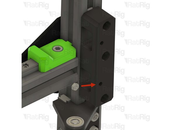
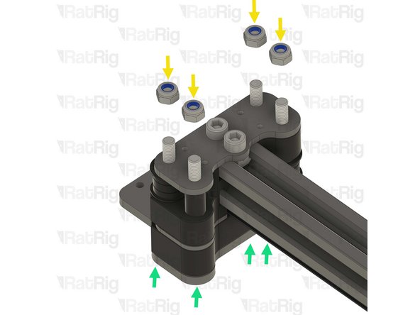
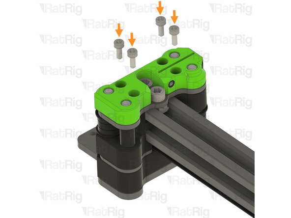
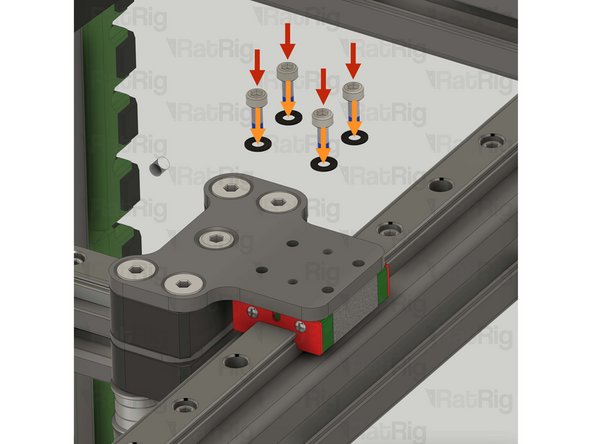
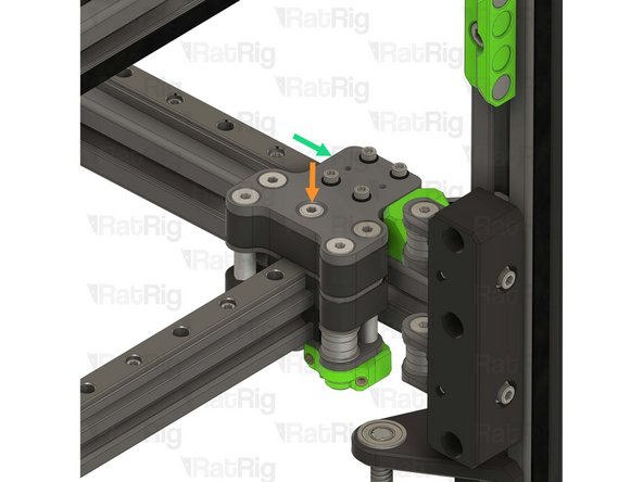
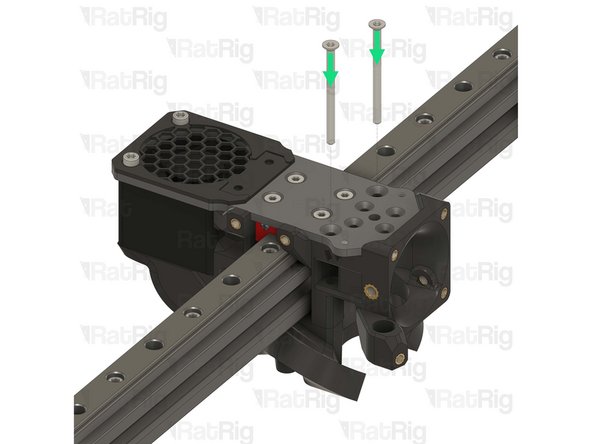
Remove the two M6x12 Cap Head Screws
-
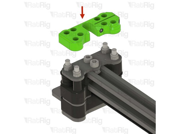
Remove the upper idler plate
-
Remove the two 3030 drop-in T-nuts from the extrusion slot
-
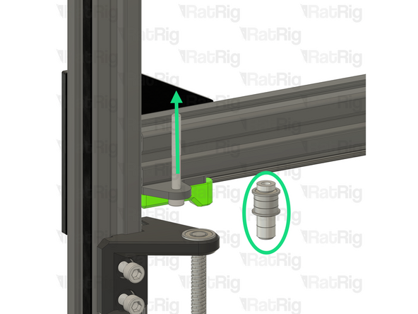
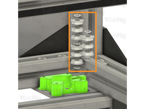
Remove the idler and spacer stack from the M5x45 Cap Head Screw
-
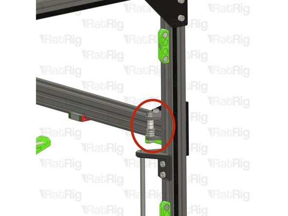
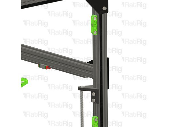
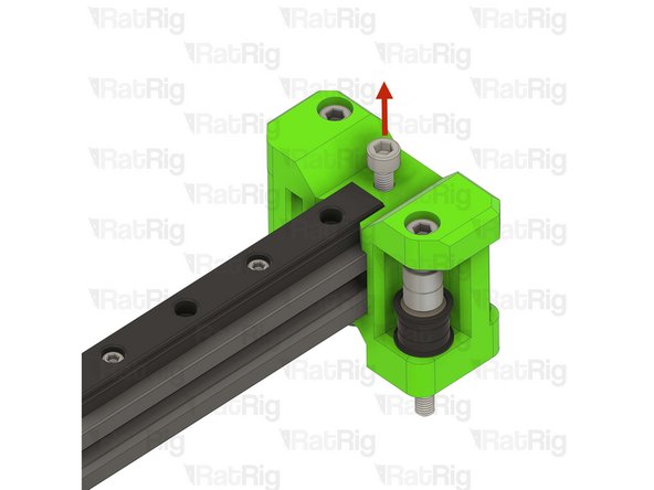
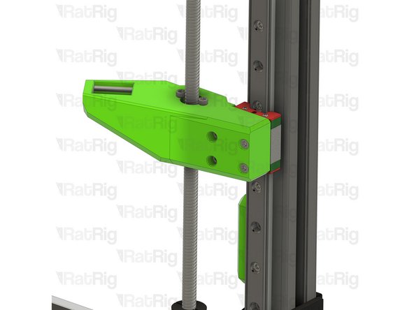
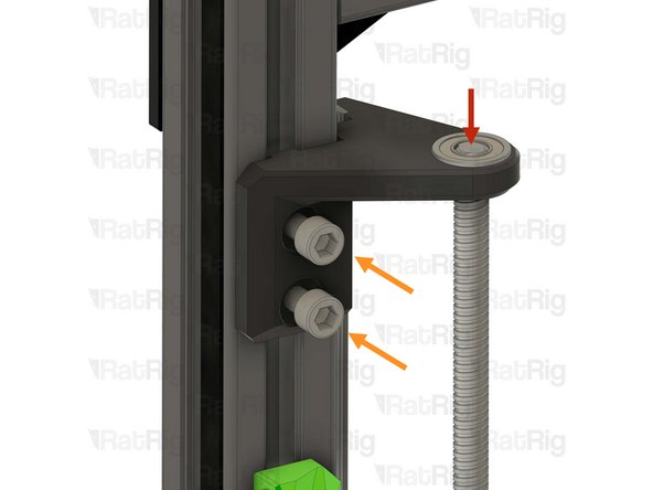
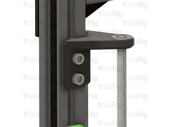
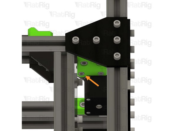
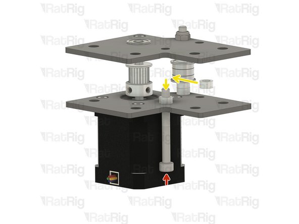
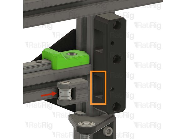
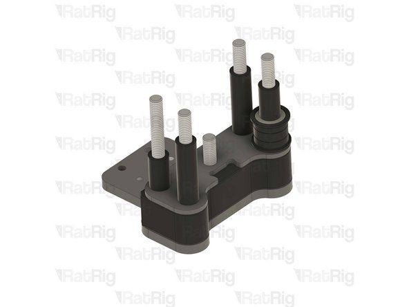
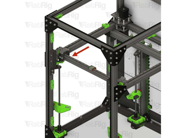
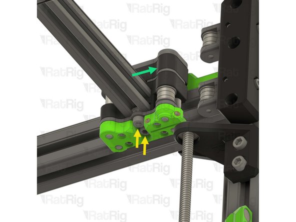
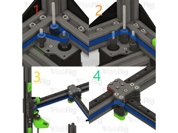
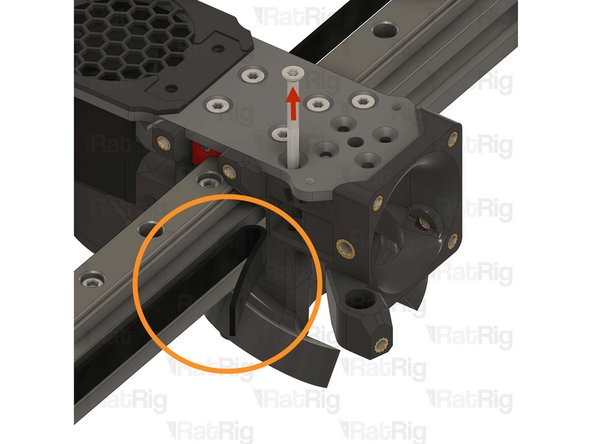
Loosen the two M6x12 Cap Head Screws holding the lead screw constraint to the frame
-
Lower the lead screw constraint assembly down to give clearance for the next step
-
-
-
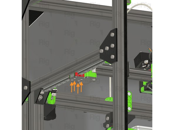
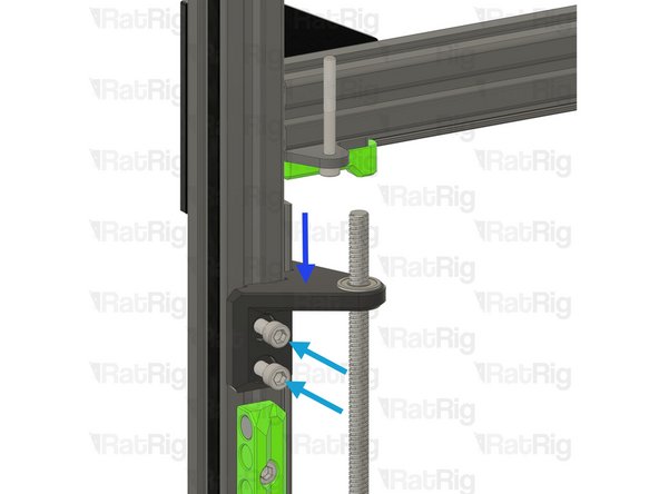
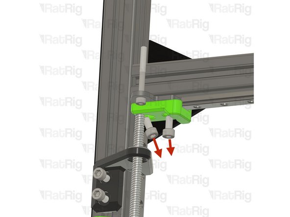
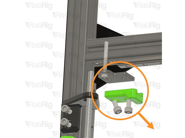
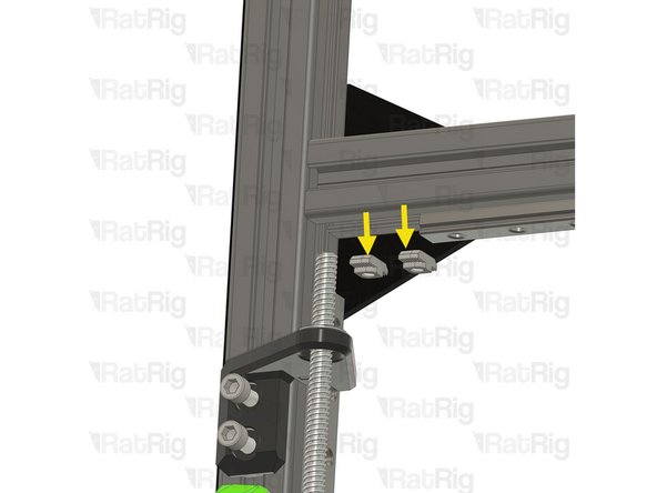
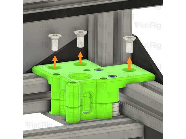
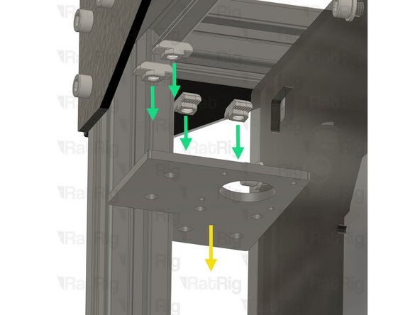
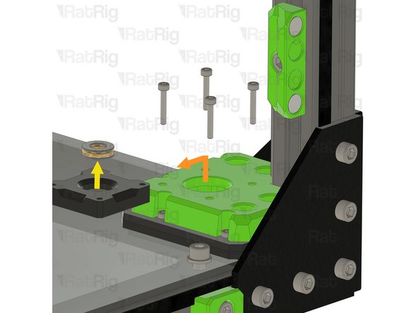
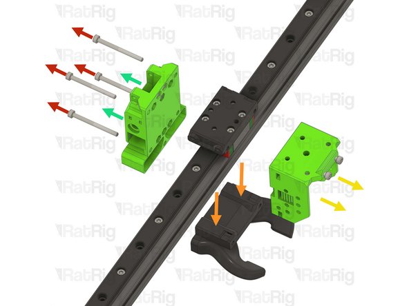
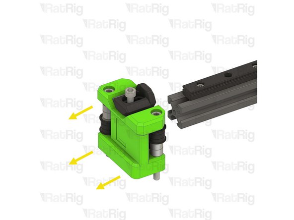
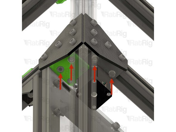
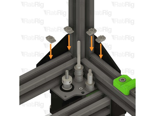
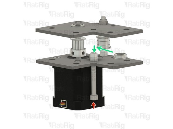
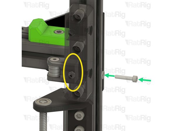
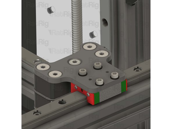
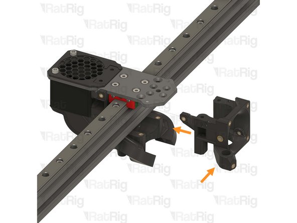
Remove the two M6x12 Cap Head Screws
-
The M6x12 Cap Head Screws might need to come out at an angle to clear the Z axis linear rail
-
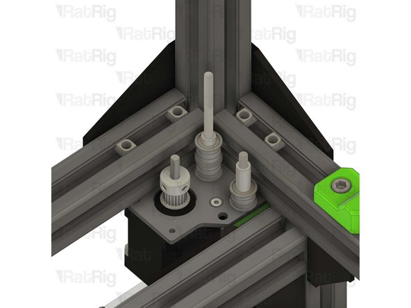
Remove the remaining parts of the front idler assembly as shown
-
Remove the two 3030 drop-in T-nuts from the extrusion slot
-
-
-
Repeat the previous 3 steps to remove the front right idler assembly
-
-
-
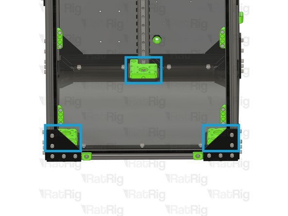
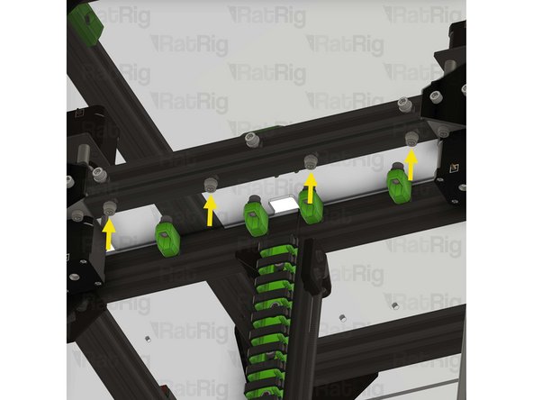
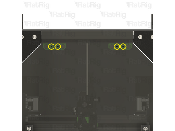
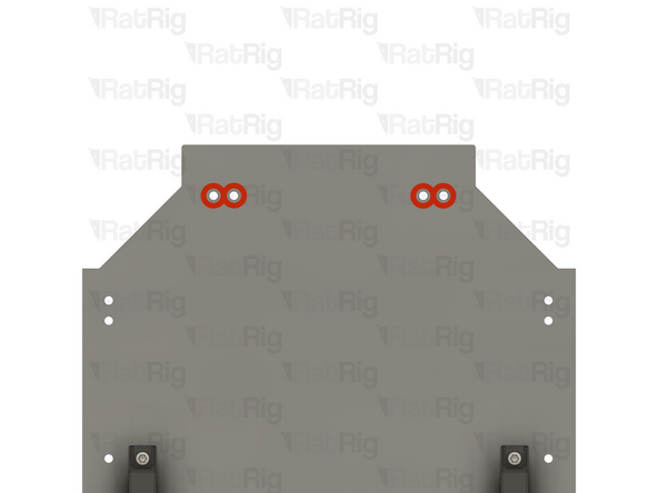
Unscrew and remove the M6x12 Cap Head Screws, and their washers
-
Remove the rear shelves
-
Remove the 3030 drop-in T-nuts from the extrusion slot
-
Reinstall the M6x12 Cap Head Screws, washers, and 3030 T-nuts into the shelves to avoid losing them
-
Set the rear shelf assemblies aside as they will be needed later
-
-
-
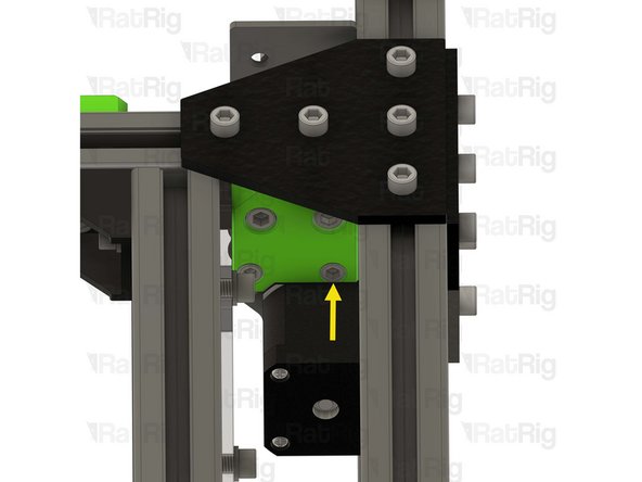
Remove the M6x12 Cap Head Screw
-
Remove the electronics wire guide printed part
-
Remove the 3030 drop-in T-nut from the extrusion slot
-
-
-
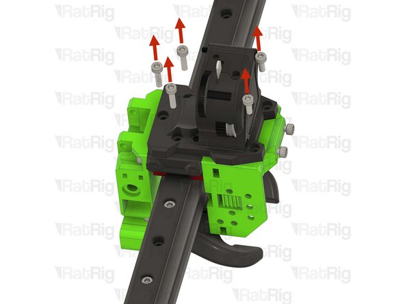
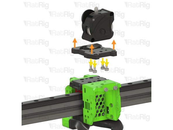
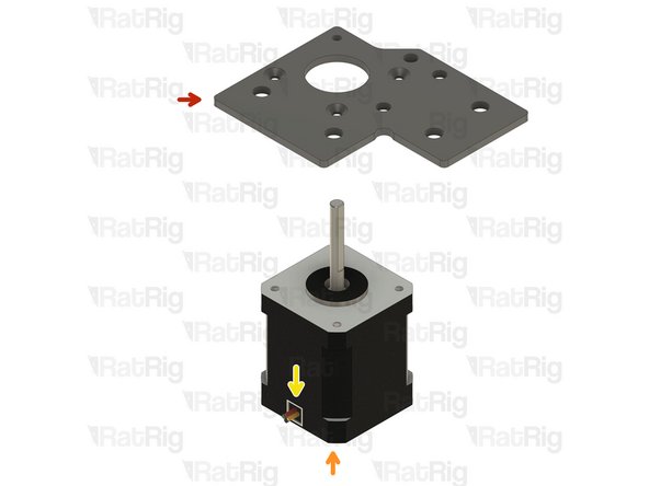
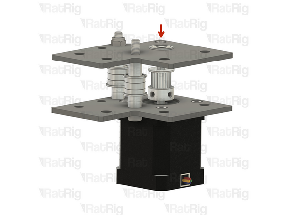
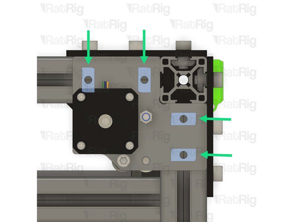
Remove the right stepper motor assembly first:
-
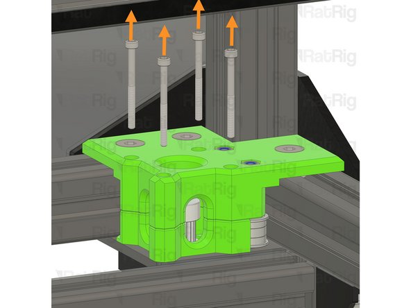
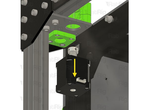
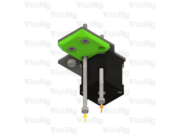
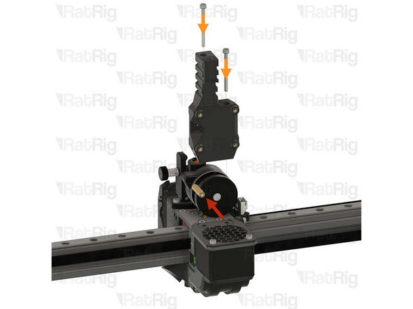
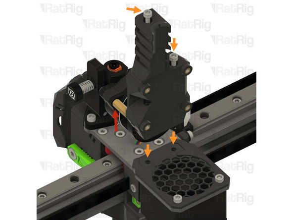
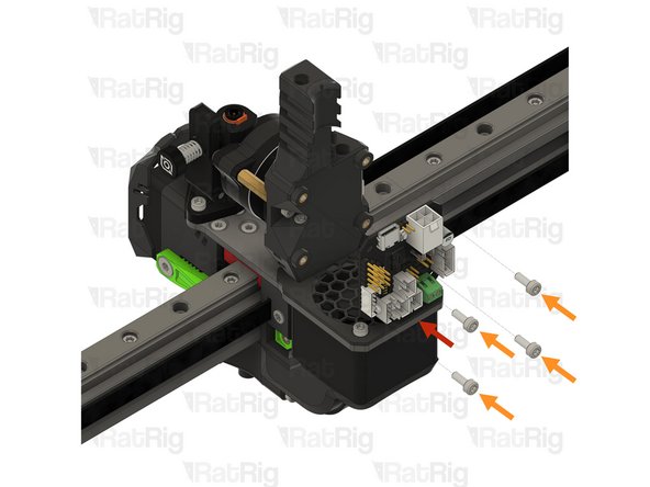
Whilst supporting the stepper motor from below, remove the four M3x35 Cap Head Screws securing the stepper motor
-
Disconnect the stepper motor cable and remove the stepper motor
-
-
-
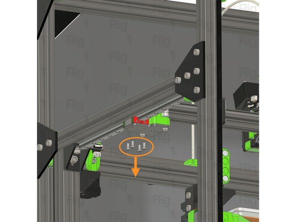
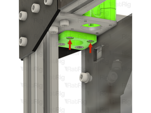
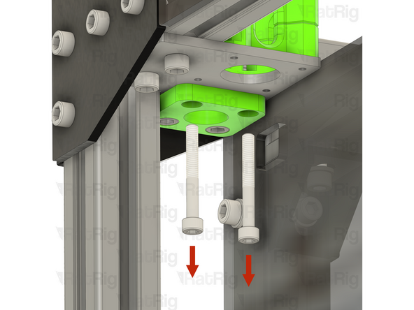
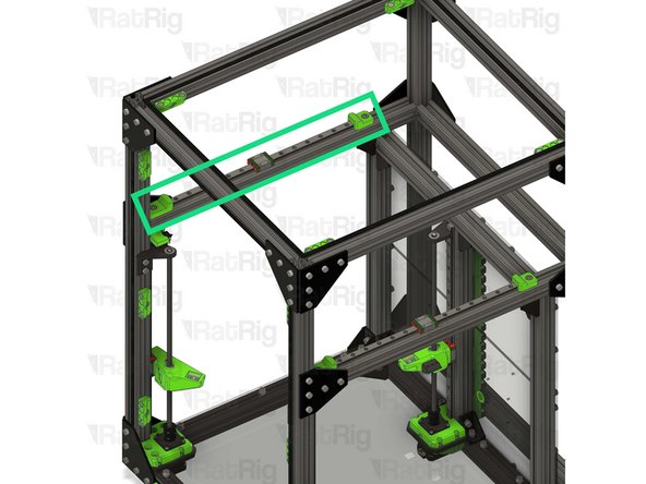
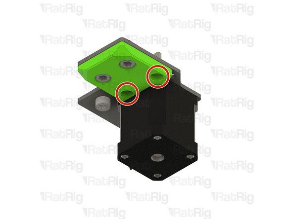
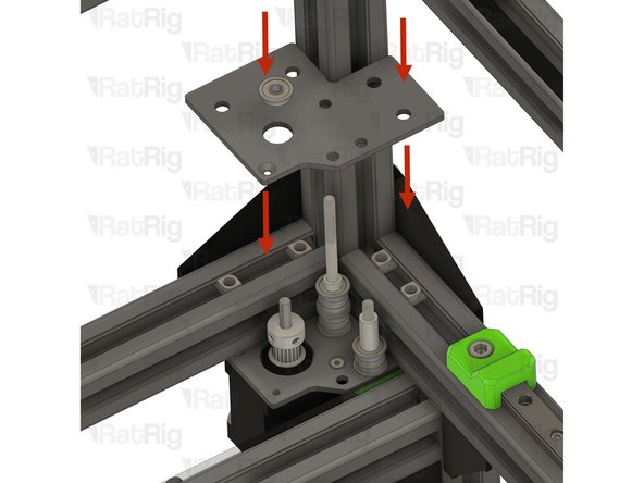
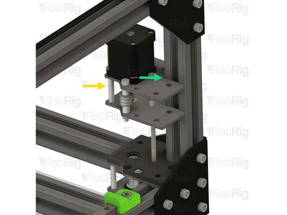
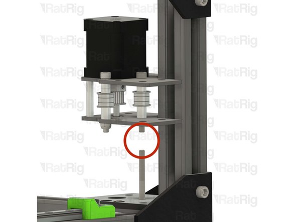
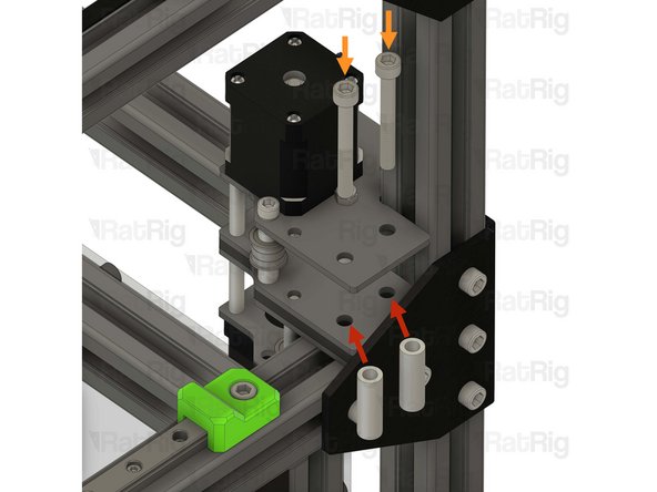
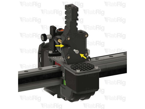
Remove the two marked M5x40 Cap Head Screws
-
Remove the three M6x14 Countersink Screws
-
-
-
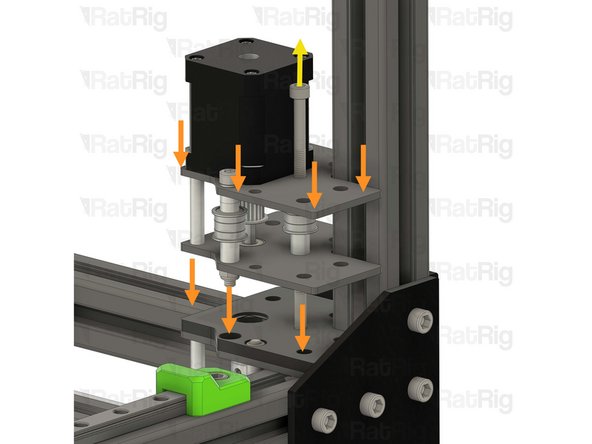
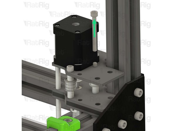
Remove the upper CoreXY stepper motor cage printed part
-
Remove all of the idler and spacer stack components
-
Remove the three 3030 drop-in T-nuts from the extrusion slot
-
Remove the lower CoreXY stepper motor cage printed part
-
-
-
Remove the four M6x12 Cap Head Screws
-
Remove the motor support printed part
-
Remove the CoreXY motor plate
-
Remove the four 3030 drop-in T-nuts from the extrusion slot
-
Repeat the previous 3 steps to remove the left stepper motor assembly
-
-
-
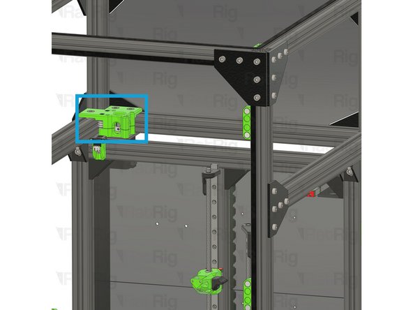
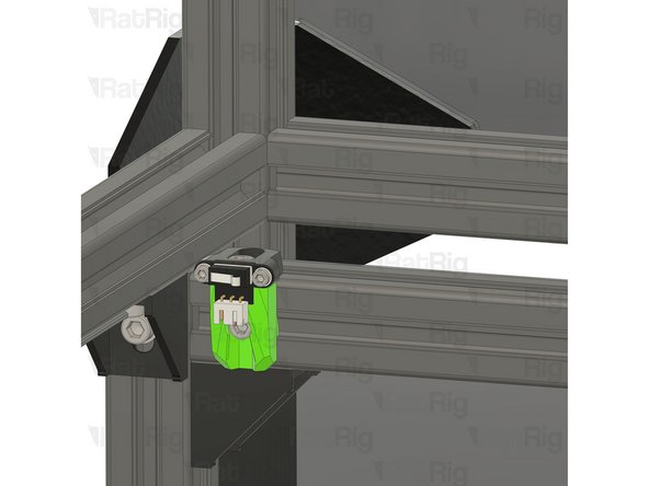
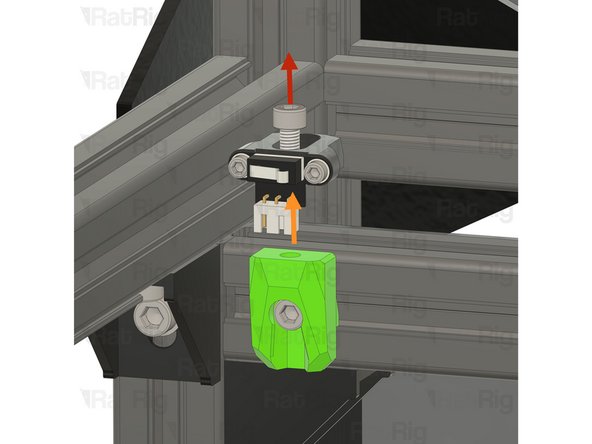
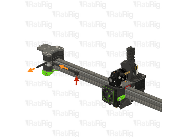
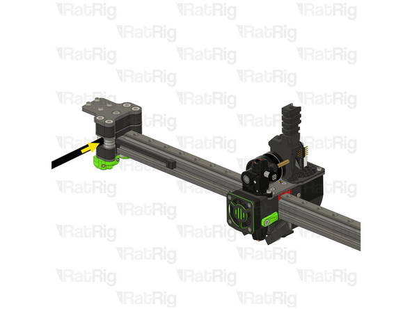
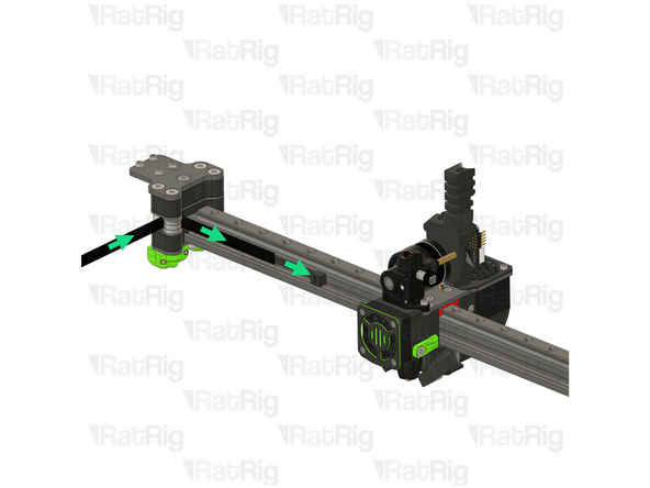
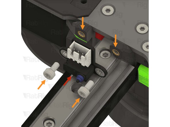
Remove the M5x12 Cap Head Screw
-
Remove the Y-axis endstop assembly from the mount
-
Loosen the M5x10 Cap Head Screw and remove the Y-axis endstop mount from the frame
-
-
-
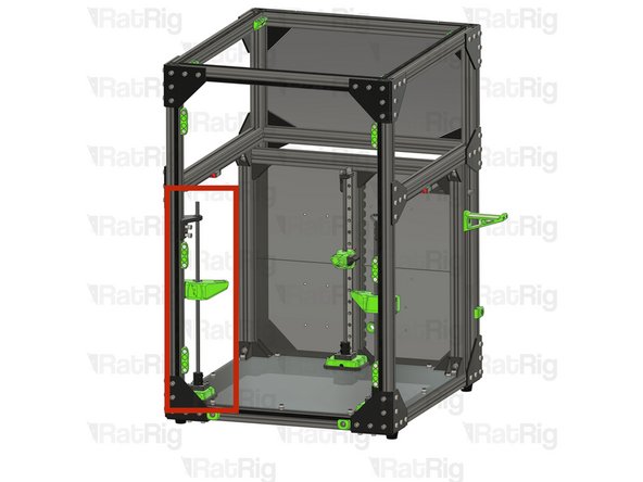
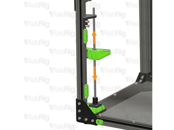
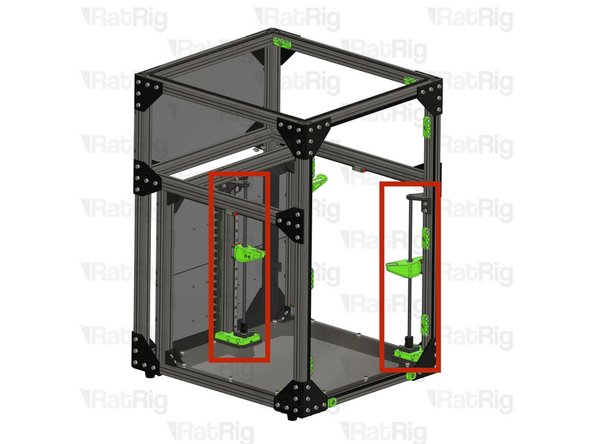
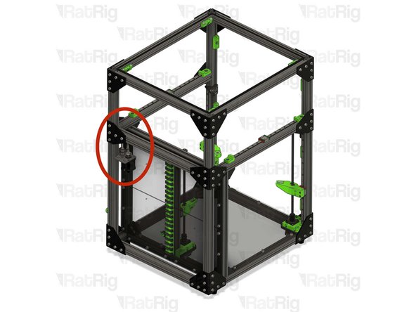
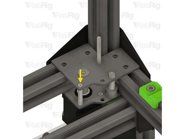
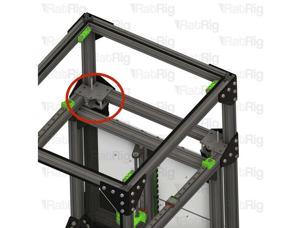
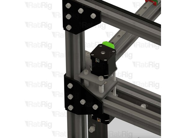
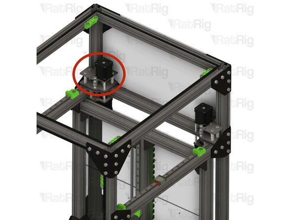
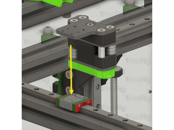
This step, and the next two steps, detail disassembling the front left Z-axis assembly
-
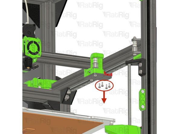
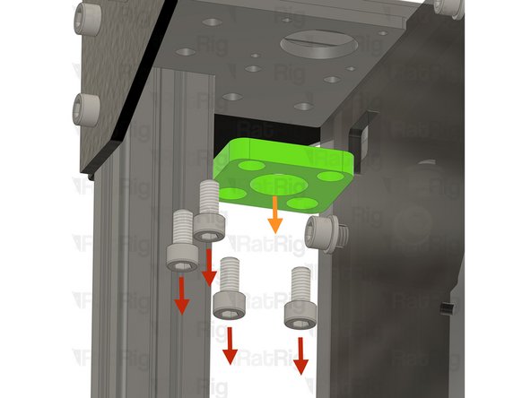
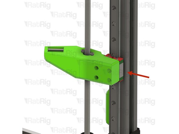
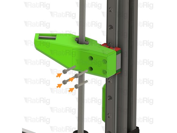
Remove the four M3x20 Cap Head Screws holding the Z-axis arm to the linear rail carriage
-
Keep these screws, they will be used in the next steps
-
-
-
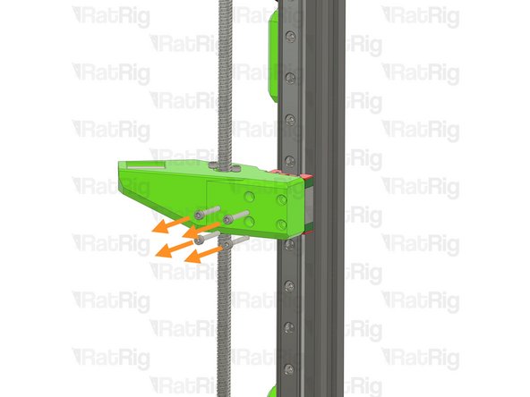
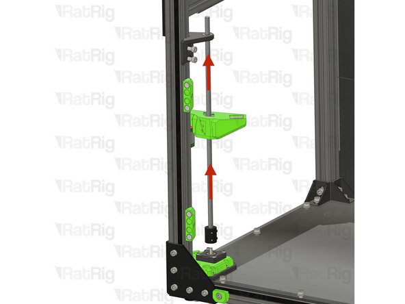
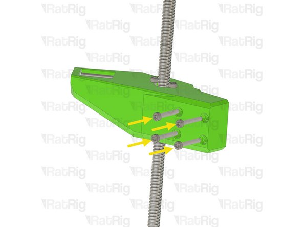
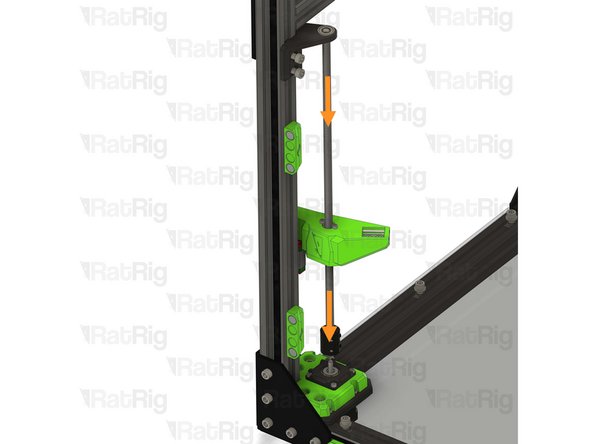
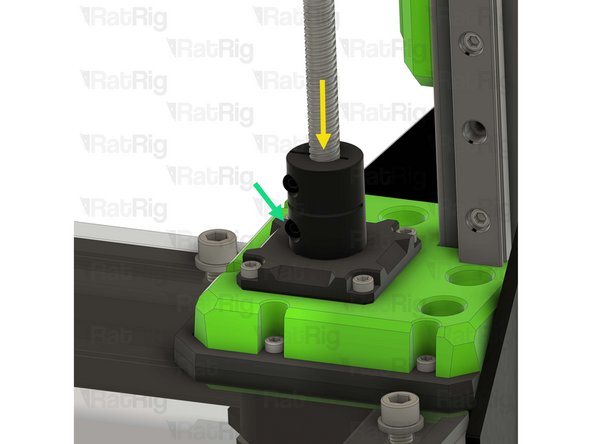
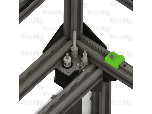
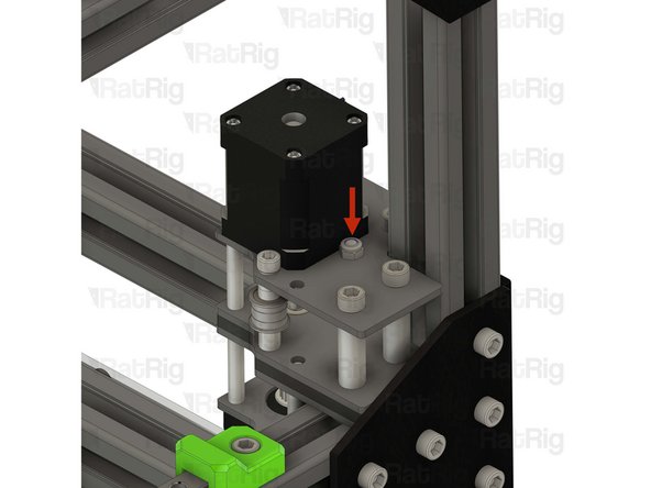
Loosen the bottom screw on the lead screw coupler
-
The Z-axis lead screw should now freely move up and down
-
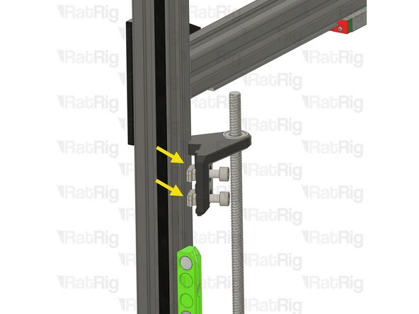
Rotate the lead screw constraint assembly so the Cap Head Screws and T-nuts come free from the extrusion slot
-
-
-
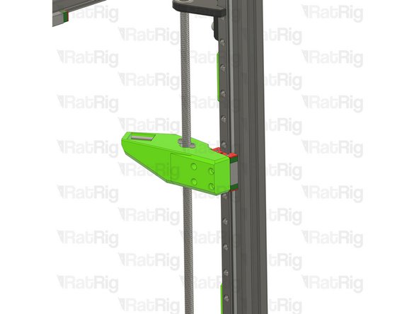
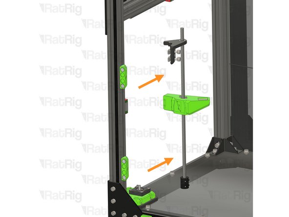
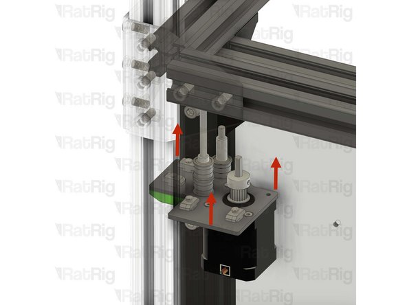
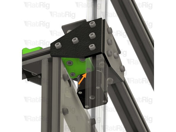
Lift the lead screw to separate the coupler from the stepper shaft
-
Remove the Z-axis assembly from the machine frame
-
Reinsert the M3x20 Cap Head Screws into the Z-axis arm holes to avoid losing them
-
-
-
Repeat the previous 3 steps to remove the front right and the rear Z-axis assemblies
-
-
-
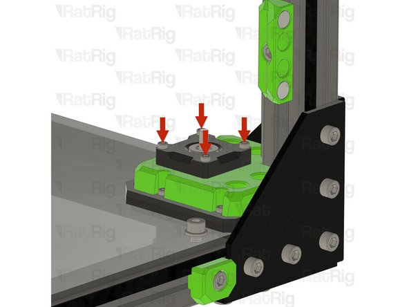
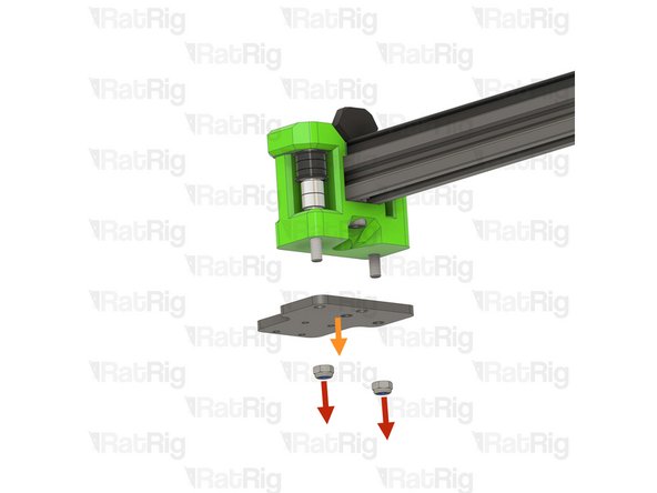
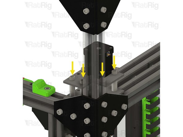
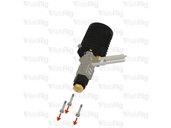
Remove the four M3x18 Cap Head Screws
-
The Z-axis stepper motor will come loose once these for screws are removed
-
Keep these screws, they will be used in later in the guide
-
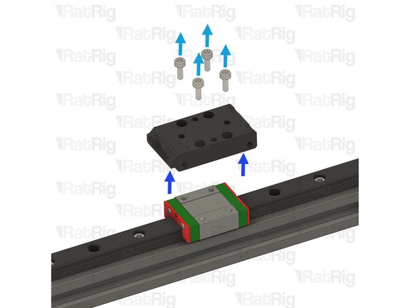
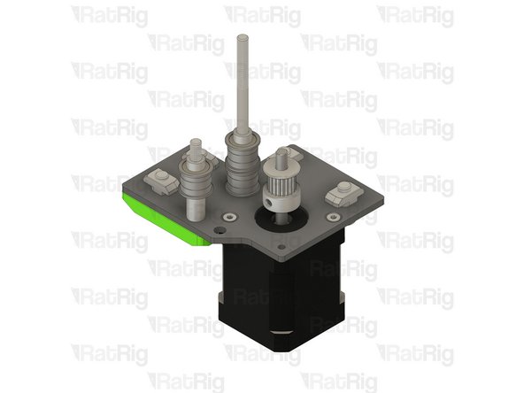
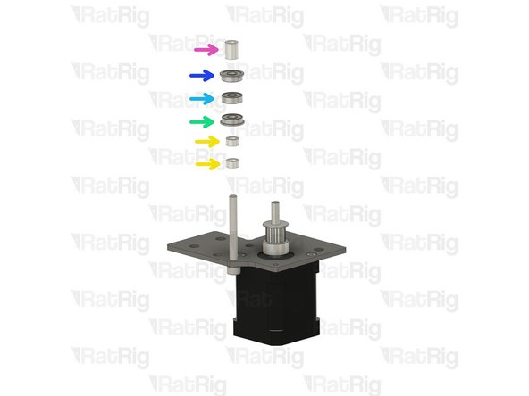
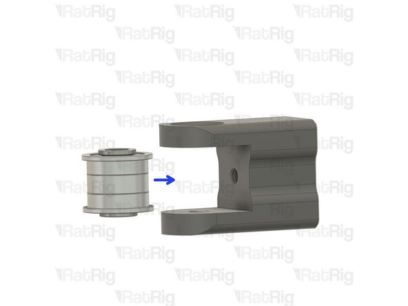
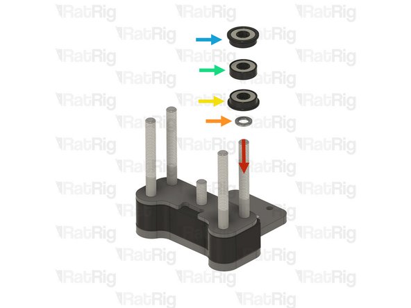
Remove the pillow block
-
Remove the thrust bearing from the pillow block
-
Keep the thrust bearing, it will be used in later in the guide
-
Repeat the above instructions to remove the remaining two pillow blocks
-
-
-
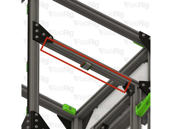
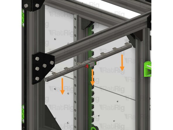
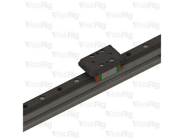
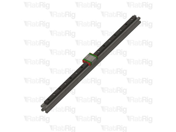
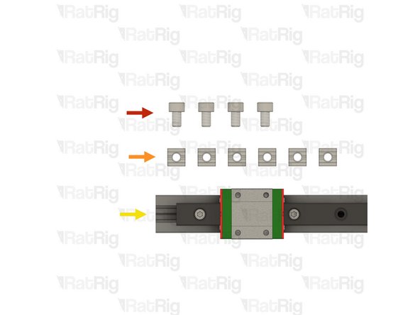
Whilst supporting the linear rail, loosen all of the M3x12 Cap Head Screws securing the linear rail to the frame
-
Carefully remove the linear rail
-
Do not allow the linear rail carriage to leave either end of the linear rail
-
Place the linear rail assembly on a flat surface
-
Repeat the above instructions to remove the remaining Y-axis linear rail
-
Set both linear rail assemblies aside, on a flat surface, they will be reinstalled later in the guide
-
-
-
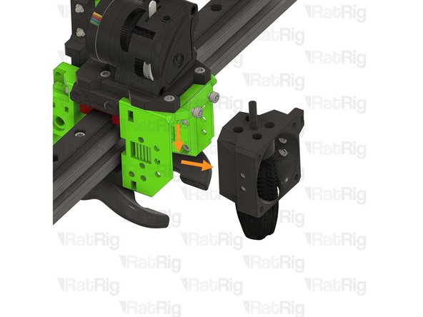
Remove the marked M3x25 Cap Head Screw
-
Remove the marked M3 hex nut
-
None of these parts will be reused in the V-Core 3.2H toolhead
-
-
-
Remove the marked M3 nylon locking hex nut
-
Remove the marked M3x35 Cap Head Screw
-
None of these parts will be reused in the V-Core 3.2H toolhead
-
-
-
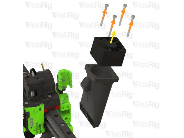
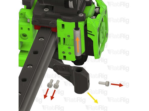
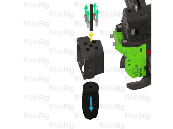
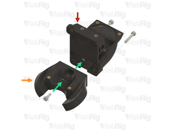
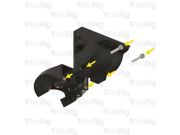
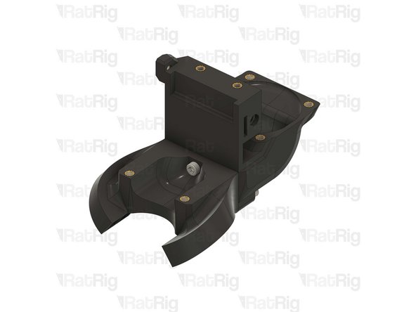
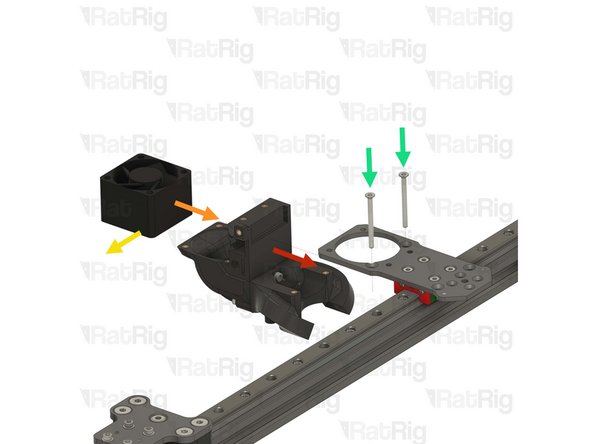
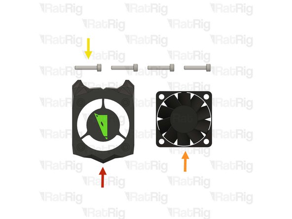
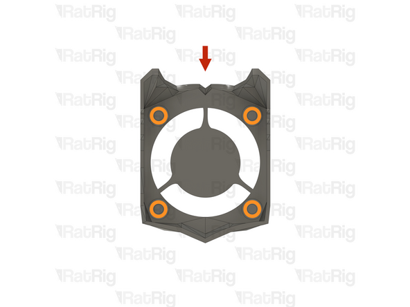
Remove the 40mm_fan_duct assembly as shown
-
Remove the four M3x35 Cap Head Screws
-
Remove the 4028 part cooling fan from the printed part
-
Keep the 4028 part cooling fan, it will be used later in the guide
-
The printed parts, and fasteners, will not be reused in the V-Core 3.2H toolhead
-
-
-
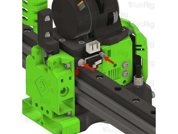
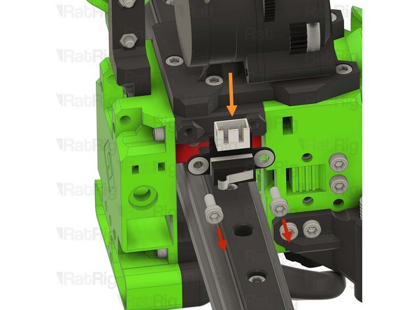
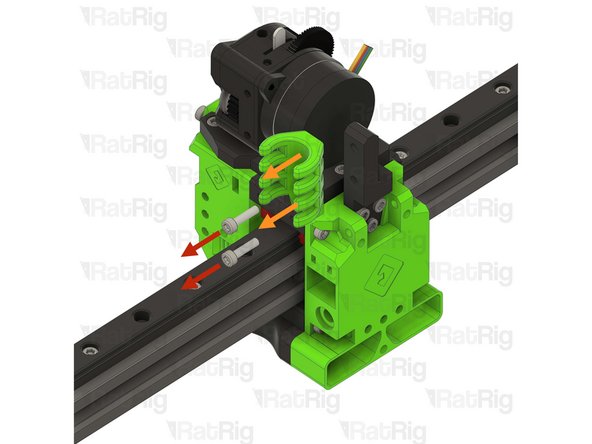
Remove the two marked M3x8 Cap Head Screws
-
Disconnect, and remove the endstop
-
None of these parts will be reused in the V-Core 3.2H toolhead
-
-
-
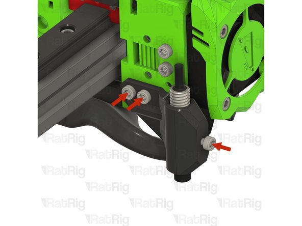
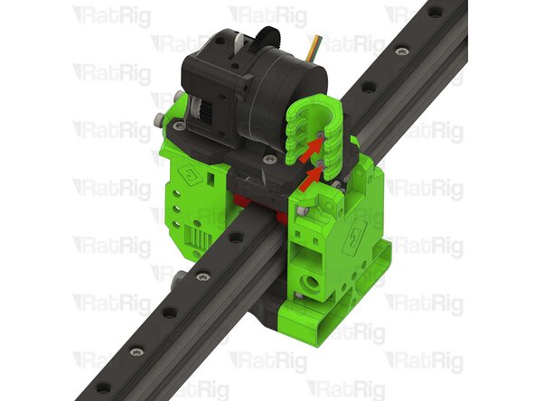
Remove the three marked M3x8 Cap Head Screws
-
Remove the Z-probe from the printed part
-
Keep the Z-probe, it will be used later in the guide
-
Remove the probe mount printed part
-
The printed parts, and fasteners, will not be reused in the V-Core 3.2H toolhead
-
-
-
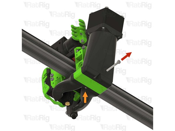
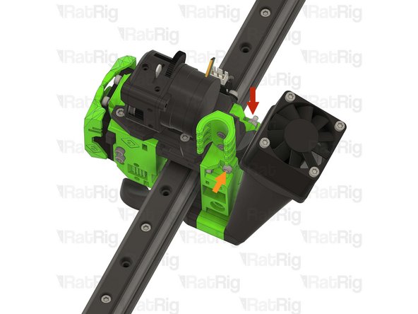
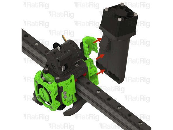
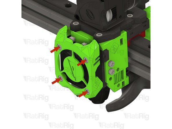
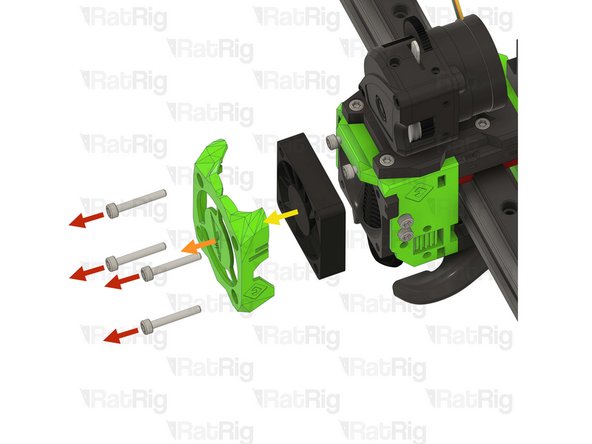
Remove the four marked M3x20 Cap Head Screws
-
Remove the printed shroud
-
Remove the 4010 hotend fan from the assembly
-
Keep the 4010 hotend fan, it will be used later in the guide
-
The printed parts, and fasteners, will not be reused in the V-Core 3.2H toolhead
-
-
-
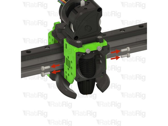
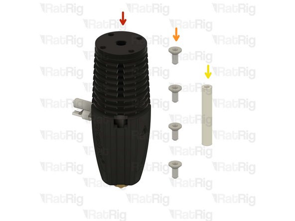
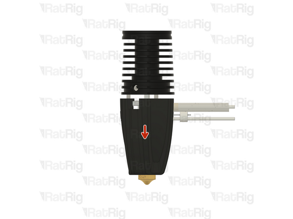
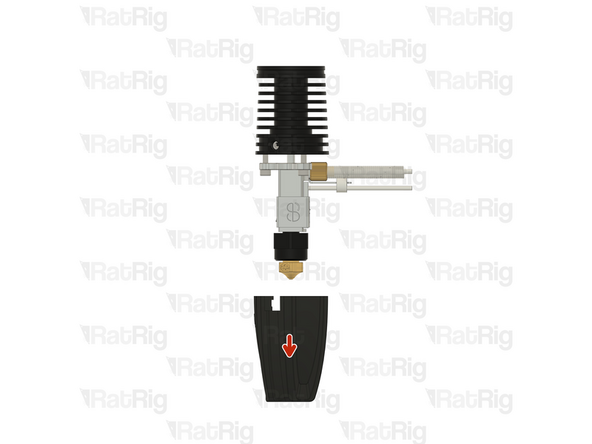
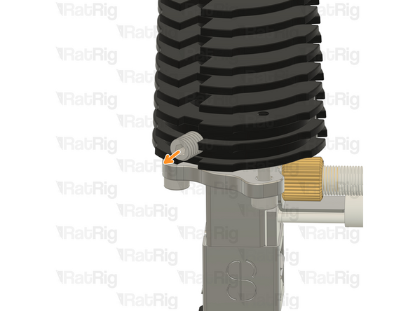
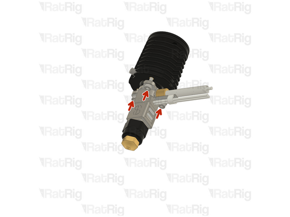
Remove the four marked M3x8 Cap Head Screws
-
Gently push the hotend assembly down and away from the toolhead
-
Remove the PTFE tube
-
Remove the four M2.5x8 Cap Head Screws
-
Remove the Rapido hotend from the printed part
-
Keep the Rapido hotend, and the PTFE tube, they will be used later in the guide
-
The printed parts, and fasteners, will not be reused in the V-Core 3.2H toolhead
-
-
-
Remove the two marked M3x12 Cap Head Screws
-
Remove the EVA cable guide printed part
-
Remove the marked three M3x8 Cap Head Screws
-
Remove the EVA cable guide mount printed part
-
None of these parts will be reused in the V-Core 3.2H toolhead
-
-
-
Remove the two M3x25 screws on the face of the LGX Lite which secure the motor in place
-
Remove the Bondtech LGX Lite motor from the back of the LGX Lite extruder
-
-
-
Remove the five marked M3 Cap Head Screws
-
Remove the extruder assembly
-
Remove the four M3x8 Cap Head Screws securing the LGX Lite to the printed part
-
Reassemble the LGX Lite so you can safely store it
-
None of these parts will be reused in the V-Core 3.2H toolhead
-
-
-
Remove the four marked M3x35 Cap Head Screws
-
Pull down on the EVA horn duct
-
Pull on the EVA front assembly to remove it
-
Pull on the EVA back assembly to remove it
-
Remove the four marked M3x8 Cap Head Screws
-
Remove the EVA mgn12 mount printed part
-
None of these parts will be reused in the V-Core 3.2H toolhead
-
-
-
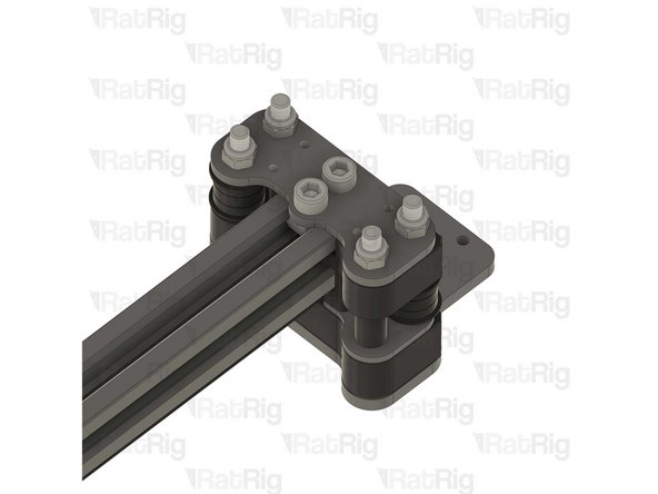
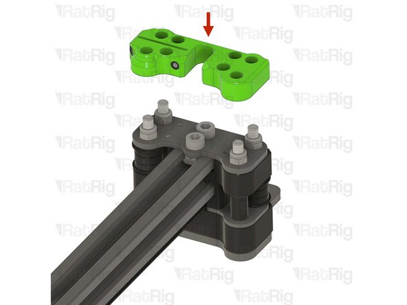
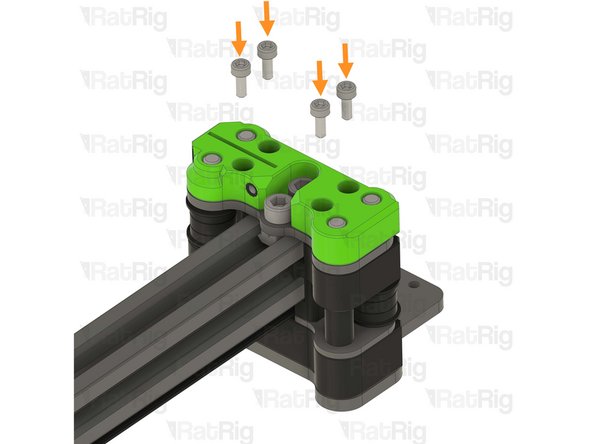
Remove the two M5 nylon locking hex nuts
-
Remove the xy_joiner_plate
-
Repeat this step for the other side of the X-axis gantry
-
None of the XY joiner parts will be reused in the V-Core 3.2H
-
-
-
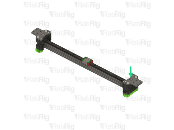
Loosen the marked M5x18 Cap Head Screw
-
Loosen the two marked M5x10 Cap Head Screws
-
Remove the left joiner from the 2020 aluminium profile
-
None of the XY joiner parts will be reused in the V-Core 3.2H
-
-
-
Loosen the marked M5x12 Cap Head Screw
-
Loosen the two marked M5x10 Cap Head Screws
-
Remove the right joiner from the 2020 aluminium profile
-
None of the XY joiner parts will be reused in the V-Core 3.2H
-
-
-
Set the linear rail and 2020 aluminium profile assembly aside, they will be reinstalled later in the guide
-
Do not allow the linear rail carriage to leave either end of the linear rail
-
-
-
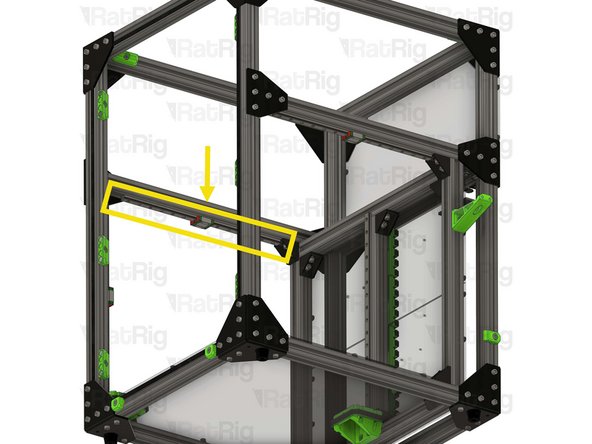
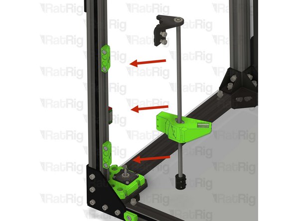
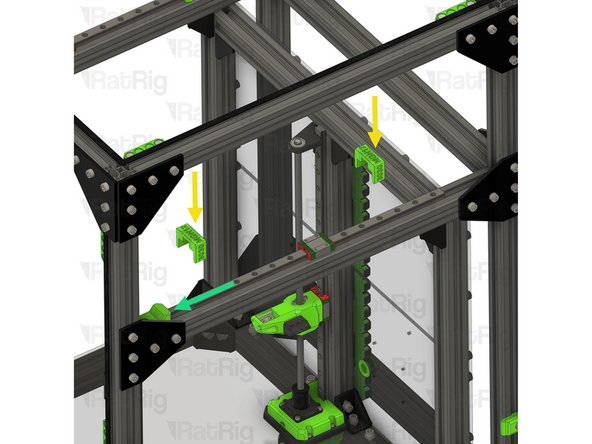
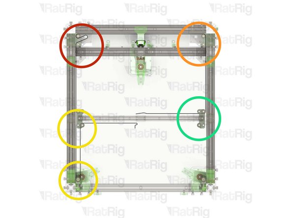
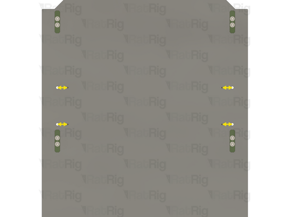
Due to a clearance issue on the V-Core 3.1 200 size only, it is necessary to relocate the upper door panel magnet holders to allow the front tensioners to be installed
-
If your V-Core 3.1 does not have enclosure panels, or you are upgrading a 300, 400 or 500 sized machine, you can skip to the next step
-
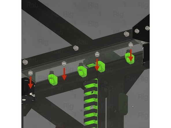
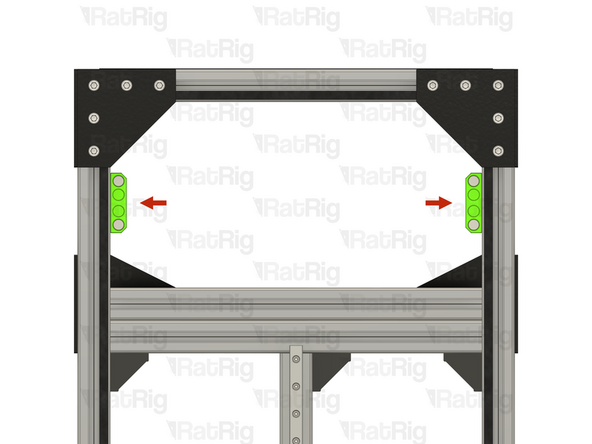
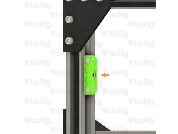
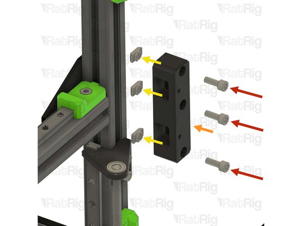
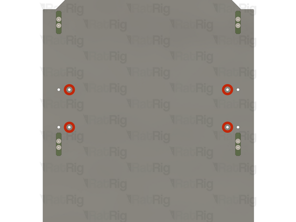
Upper magnet holders
-
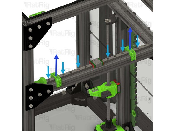
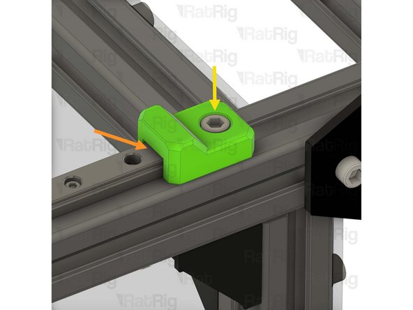
Loosen the M6x12 Cap Head Screw in each of the two upper magnet holders
-
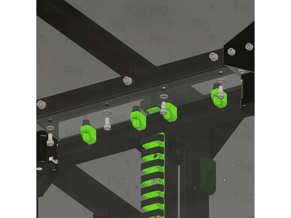
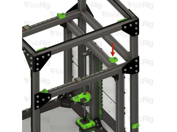
Relocate the two magnet holders to the top 3030 extrusion as shown
-
The marked gap should measure 5mm
-
Tighten the two M6x12 Cap Head Screws to secure the magnet holders to the frame
-
-
-
The following steps will guide you through assembling and installing the V-Core 3.2H upgrade
-
-
-
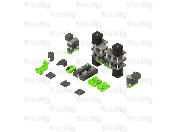
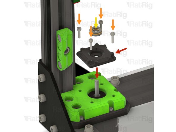
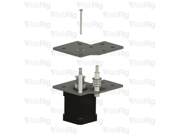
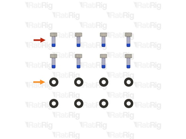
3x vc32h_pillow_block printed part
-
12x M3x12 Cap Head Screw
-
3x Axial thrust bearing
-
The axial thrust bearings are reused from step 35
-
-
-
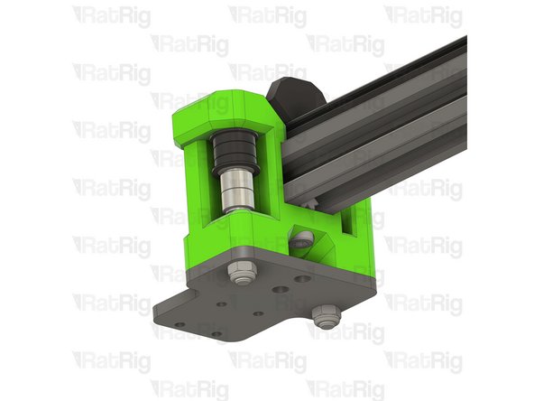
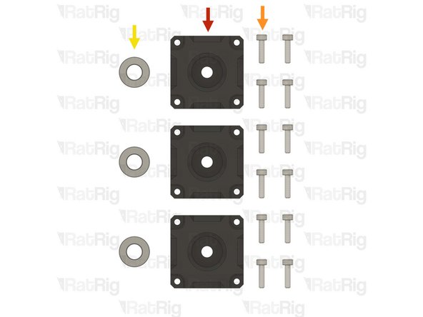
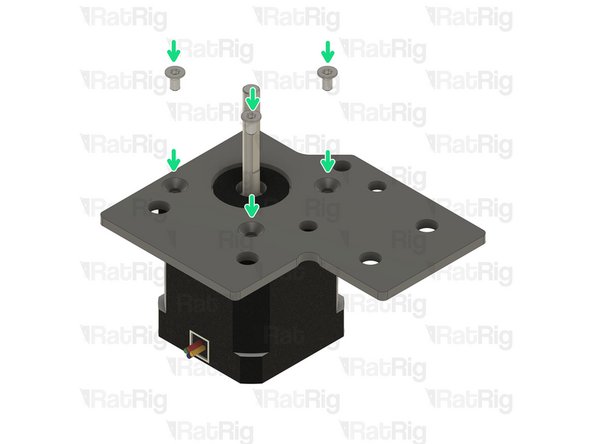
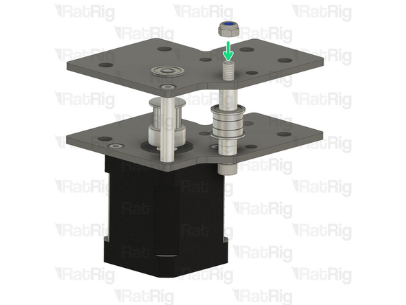
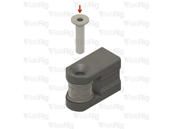
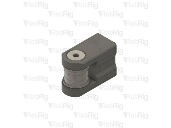
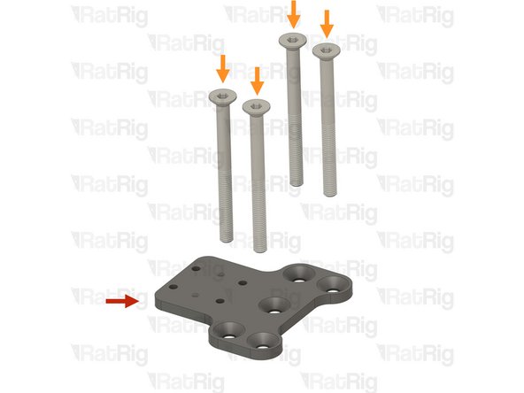
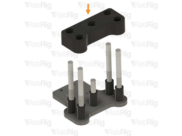
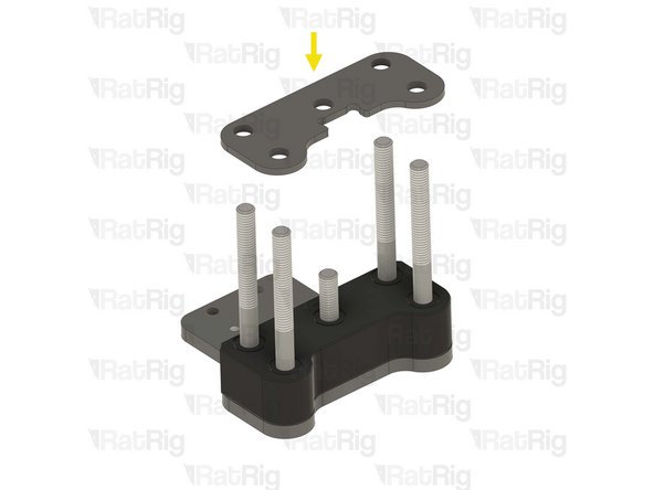
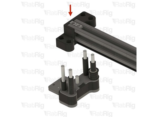
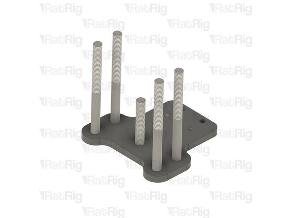
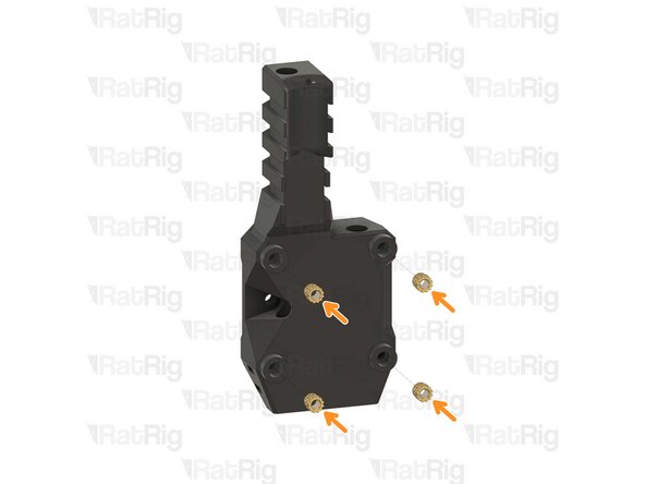
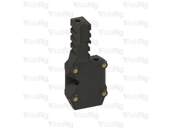
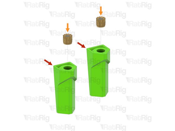
vc32h_pillow_block
-
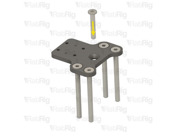
M3x12 Cap Head Screw
-
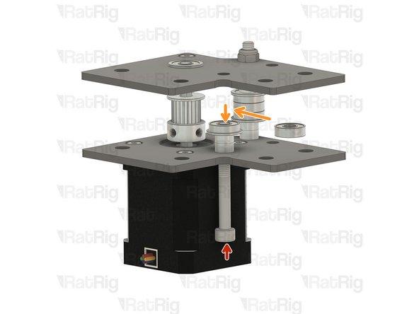
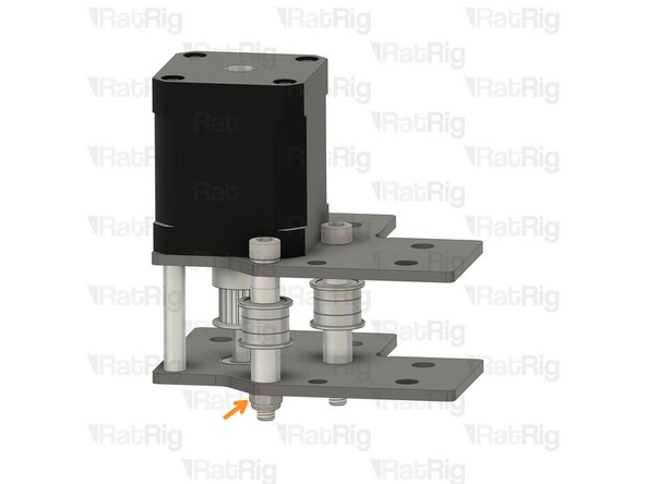
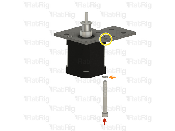
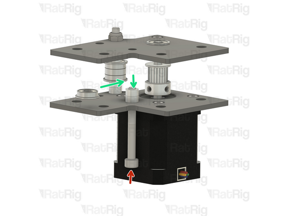
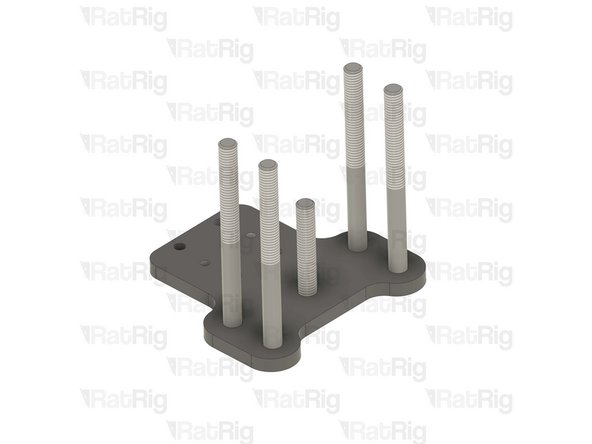
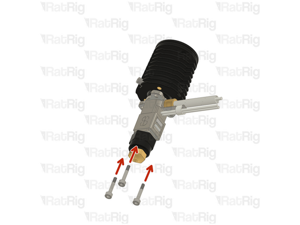
Insert each M3x12 Cap Head Screw through the pillow block, the lead screw motor cage, and fasten them into the NEMA17 motor
-
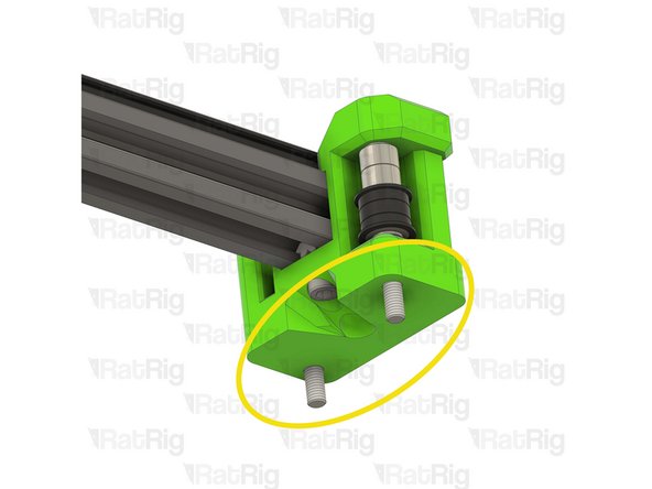
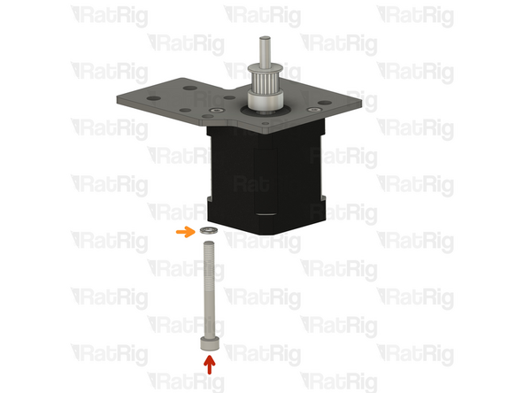
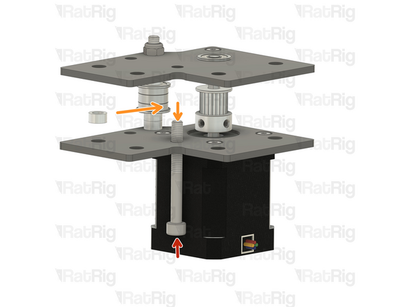
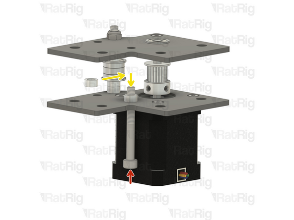
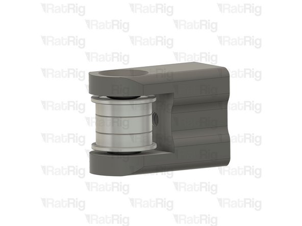
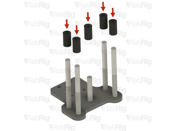
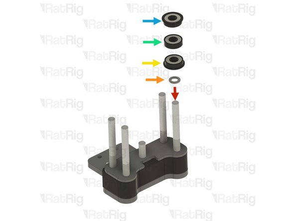
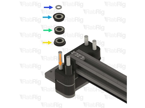
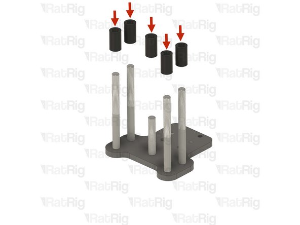
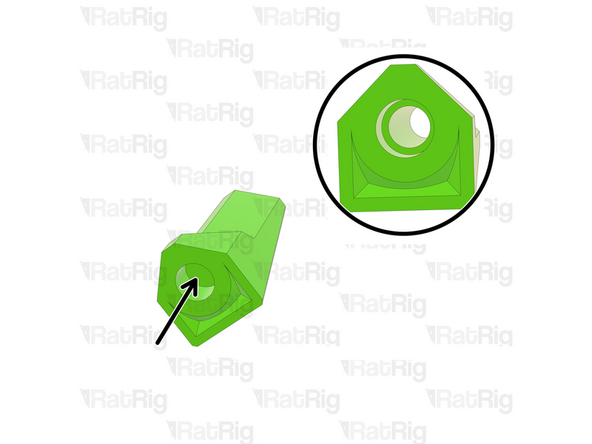
Axial thrust bearing
-
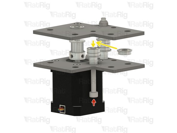
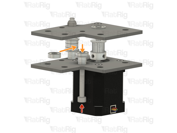
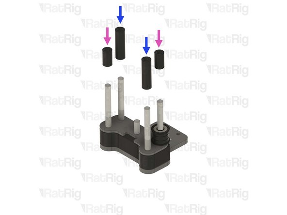
The axial thrust bearing has three components. Two end caps and an inner bearing assembly
-
If desired, you may add a drop of light oil to the inner bearing assembly of the thrust bearing
-
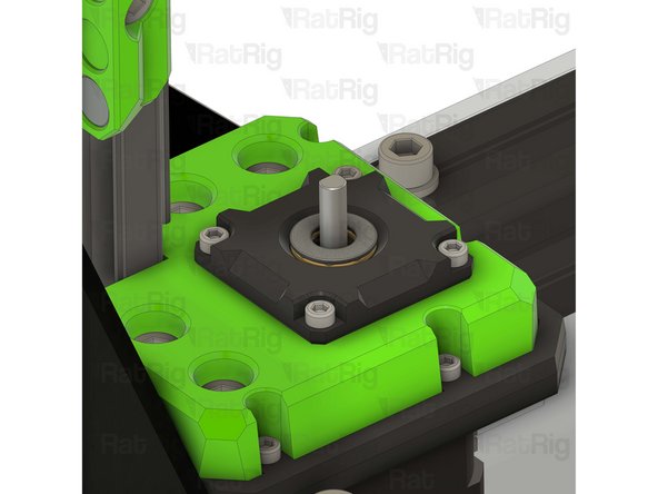
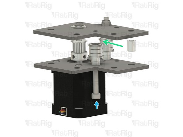
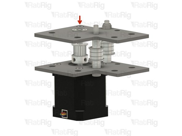
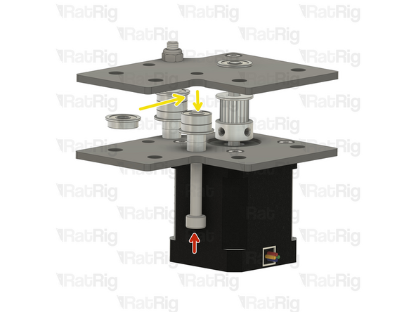
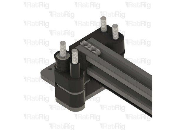
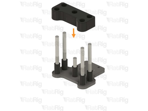
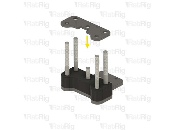
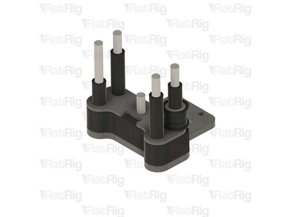
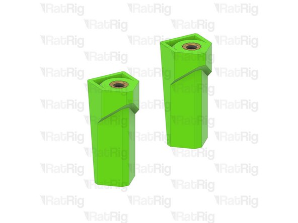
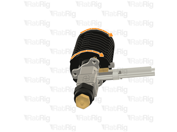
Make sure that the thrust bearing is fully inserted into the printed part. The top ring of the thrust bearing should be flush with the top of the pillow block
-
Repeat this step for the other 2 pillow blocks
-
-
-
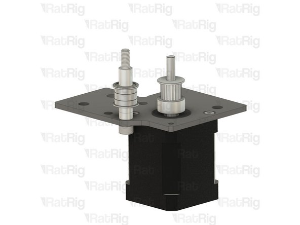
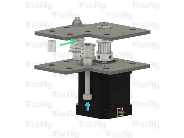
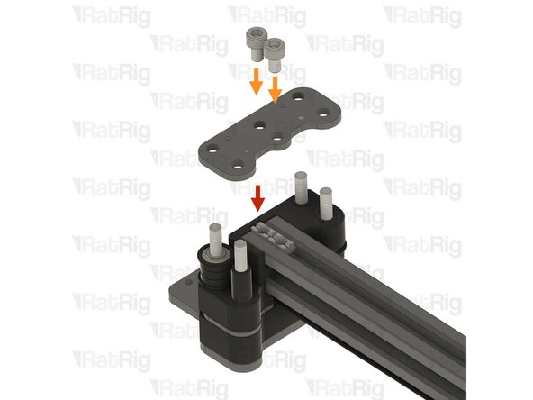
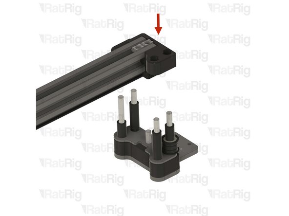
Reinstall the Z-axis transmission subassembly
-
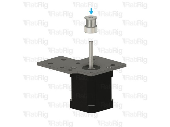
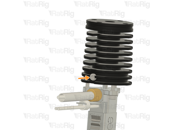
Install the lead screw coupler on to the exposed shaft of the NEMA17 motor
-
Apply downward pressure to the top of the lead screw coupler whilst tightening the marked screw
-
Tighten the marked M3 screw to secure the lead screw coupler to the motor shaft
-
-
-
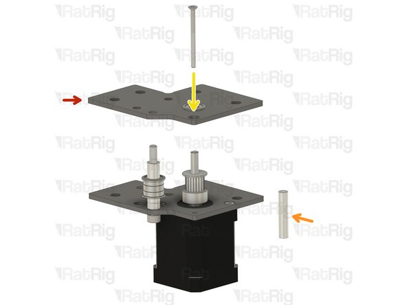
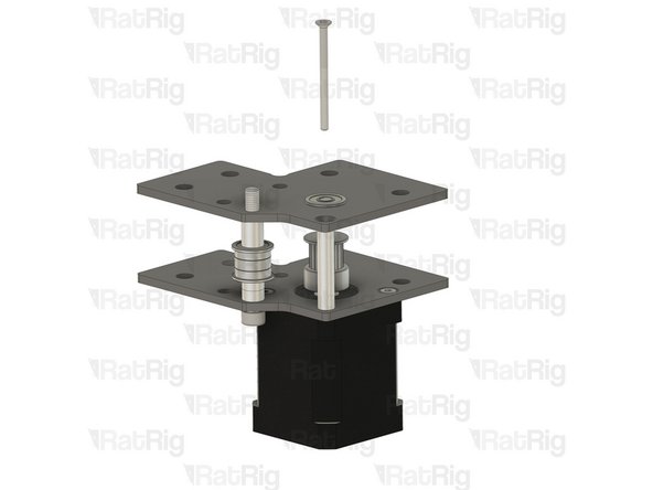
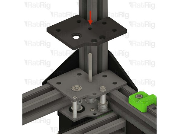
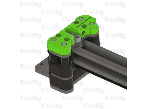
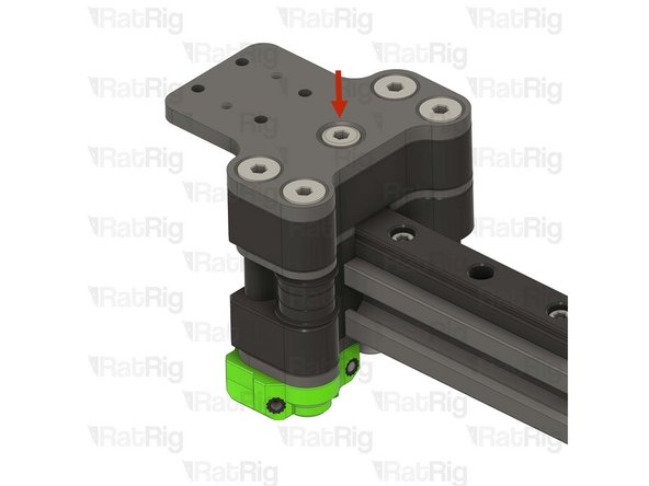
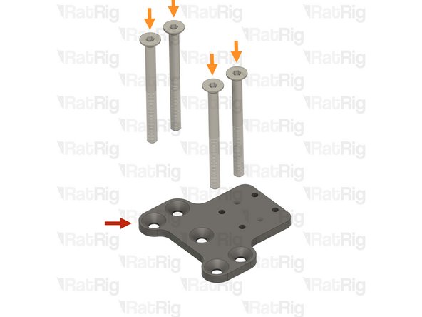
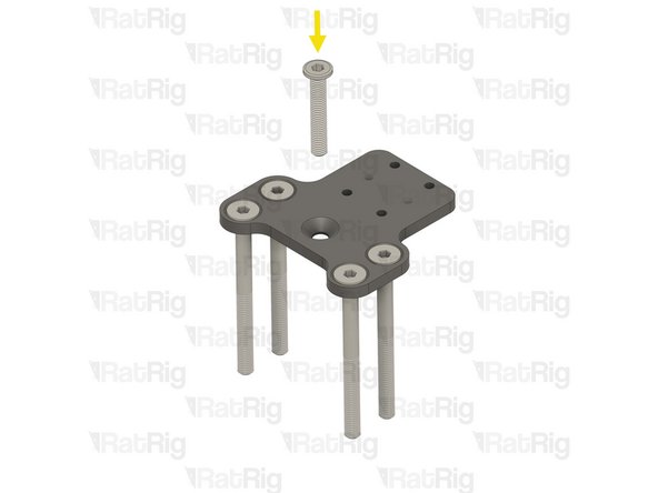
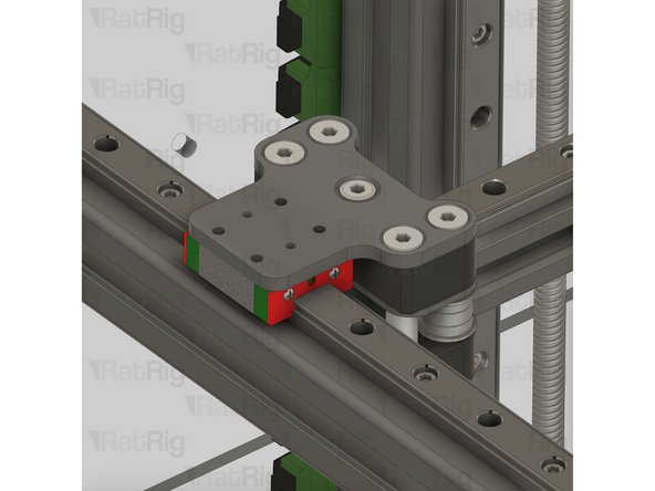
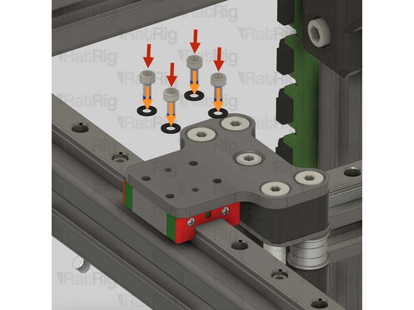
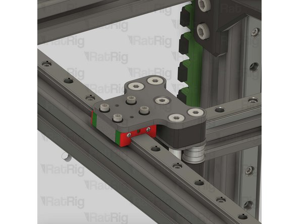
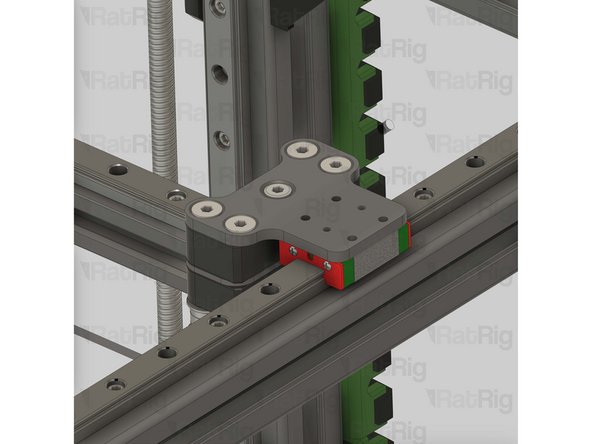
Align the bed arm with the MGN carriage as shown
-
Tighten the four M3x20 Cap Head Screws to secure the arm to the carriage
-
Do not overtighten the M3 Cap Head Screws as you damage the printed parts
-
-
-
Position the lead screw constraint assembly so that the left lead screw passes through the bearing
-
Fasten both M6x12 Cap Head Screws to secure the constraint assembly to the V-Core 3 frame
-
Do not overtighten the M6 Cap Head Screws as you damage the printed part
-
Repeat the previous steps and install the other 2 lead screw subassemblies
-
-
-
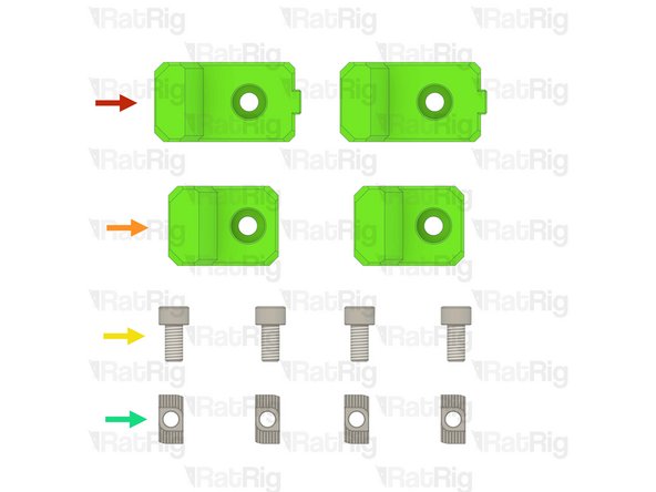
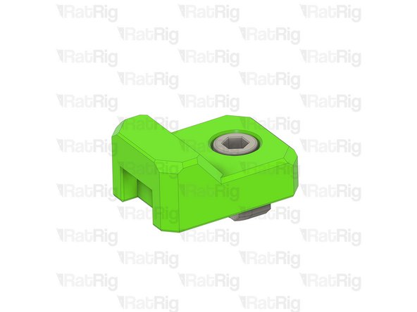
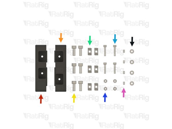
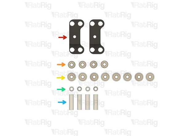
2x vc32h_y_bumper printed part
-
2x vc32h_ymax_bumper printed part
-
4x M6x12 Cap Head Screw
-
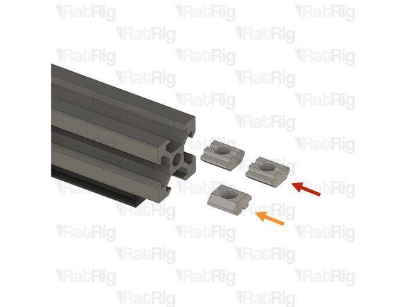
4x 3030 Drop-in T-nut - M6
-
-
-
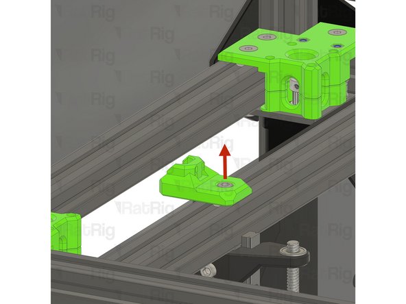
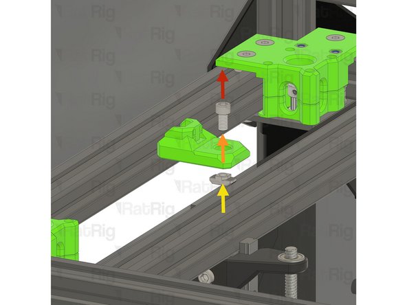
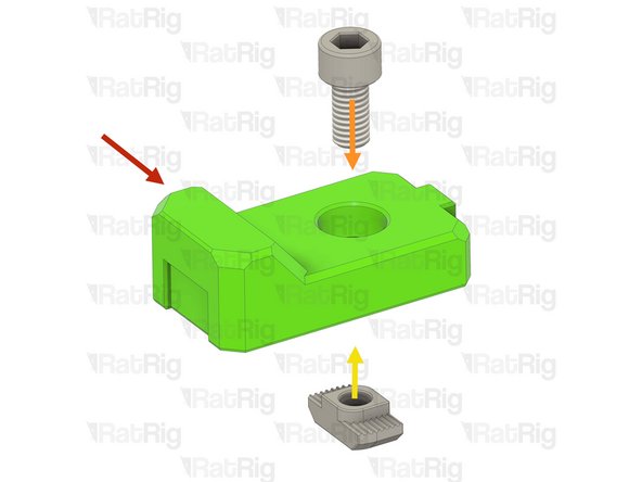
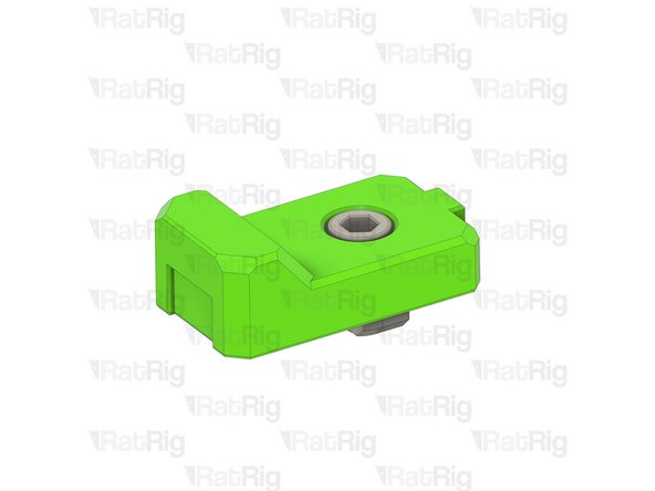
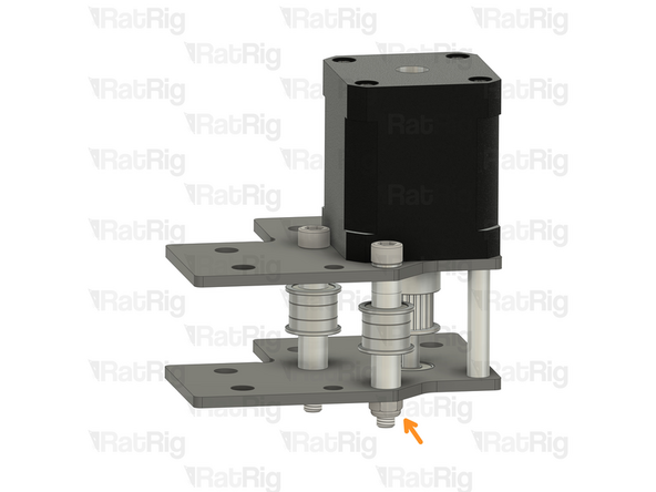
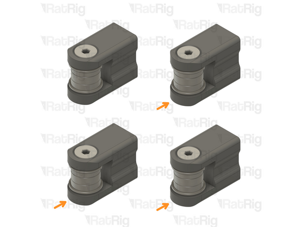
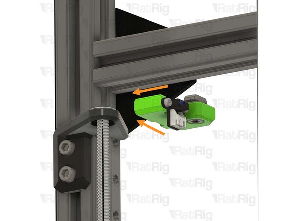
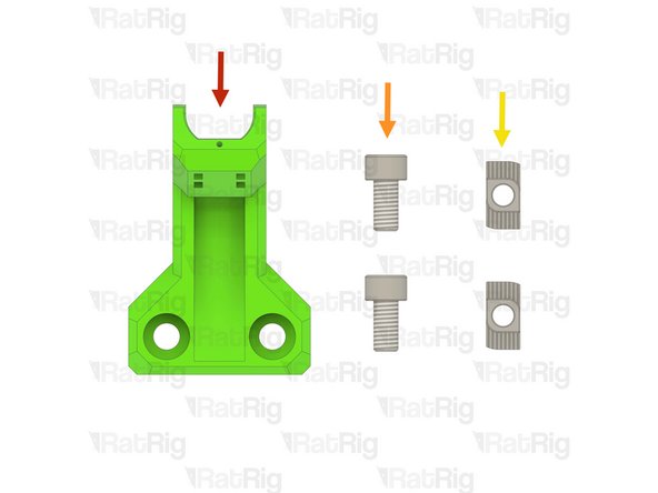
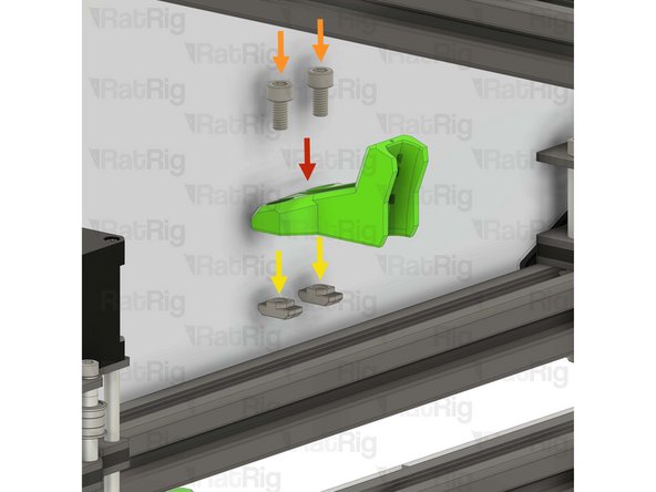
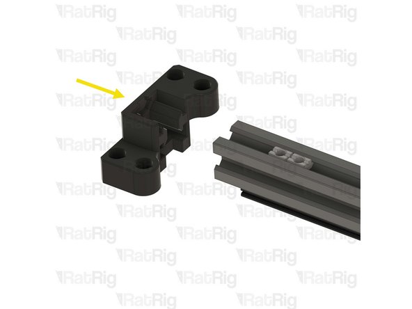
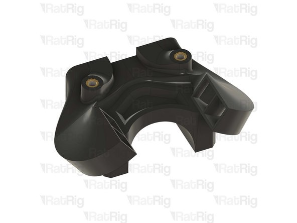
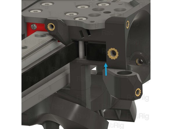
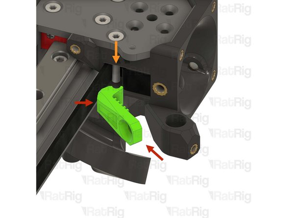
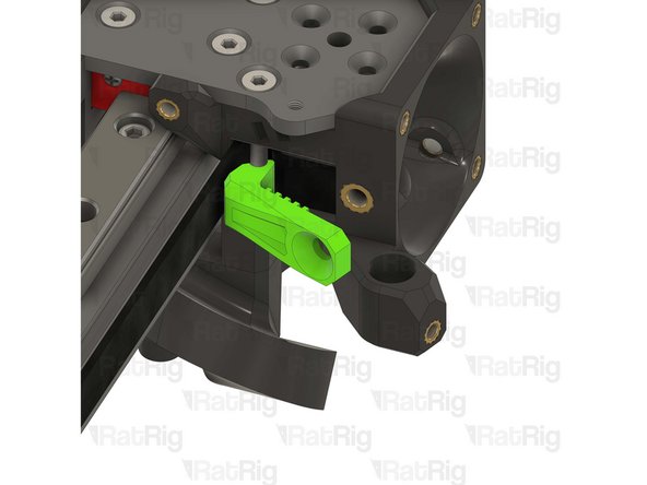
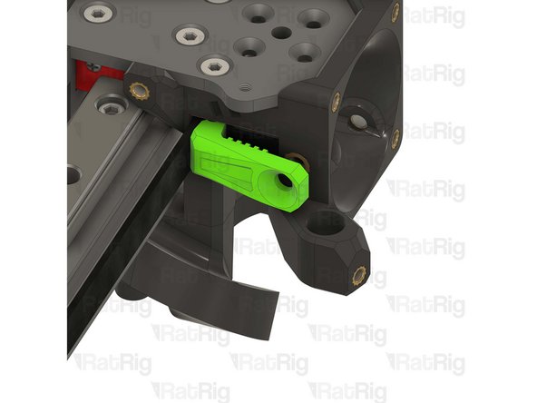
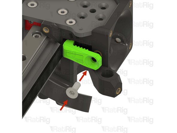
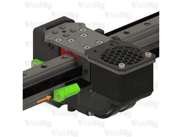
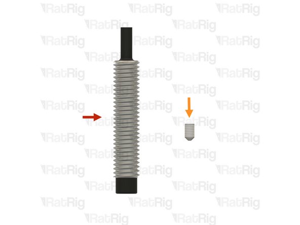
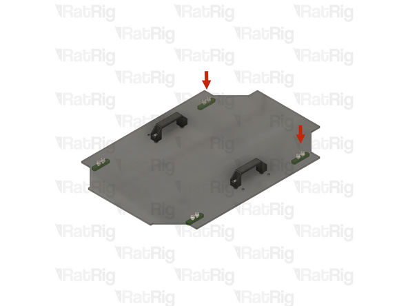
vc32h_y_bumper printed part
-
1x M6x12 Cap Head Screw
-
Install the M6 Cap Head Screw into the Y-axis bumper as shown
-
1x 3030 Drop-in T-nut - M6
-
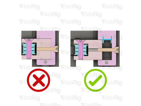
Loosely thread a 3030 T-nut onto the M6x12 screw. Do not tighten it at this point
-
Prepare two of these assemblies
-
-
-
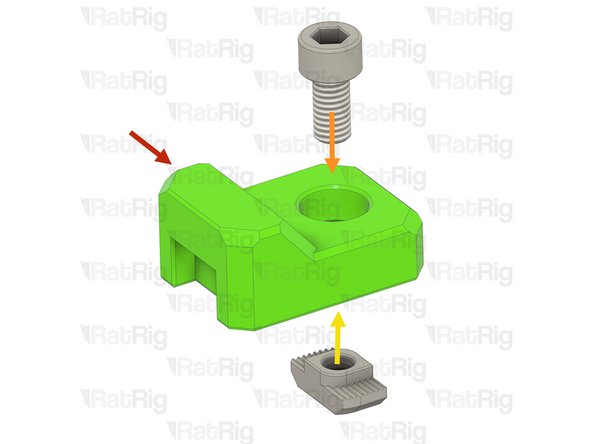
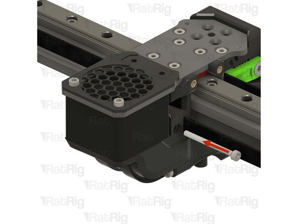
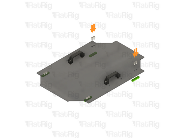
vc32h_ymax_bumper printed part
-
1x M6x12 Cap Head Screw
-
Install the M6 Cap Head Screw into the Y-max bumper as shown
-
1x 3030 Drop-in T-nut - M6
-
Loosely thread a 3030 T-nut onto the M6x12 screw. Do not tighten it at this point
-
Prepare two of these assemblies
-
-
-
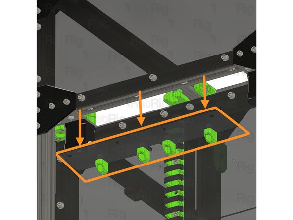
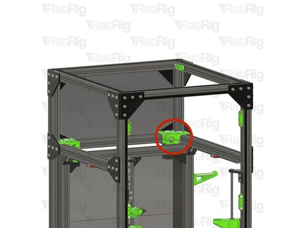
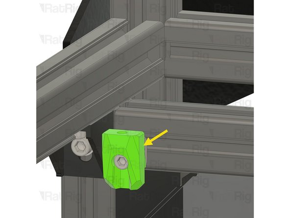
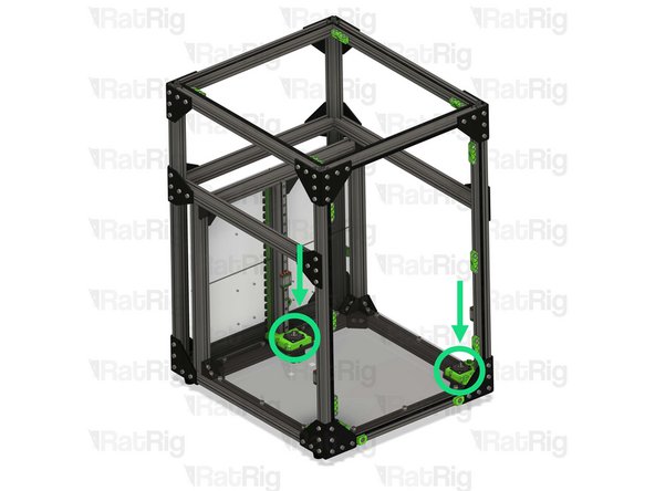
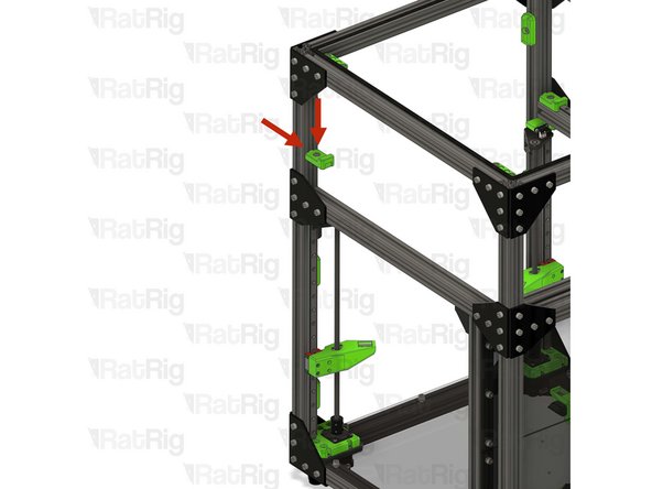
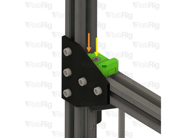
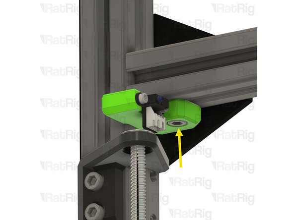
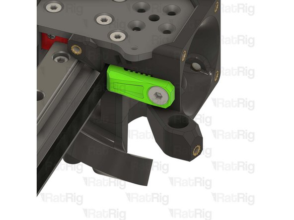
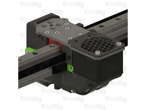
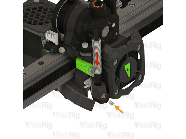
Y-min bumper assemblies from step 60
-
Make sure the printed part is fully inserted in the frame extrusion's slot
-
Tighten the M6x12 Cap Head Screw
-
Do not overtighten the M6x12 Cap Head Screws as you damage the printed parts
-
-
-
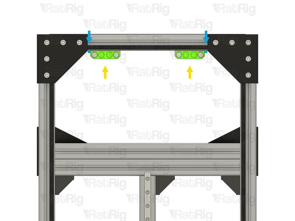
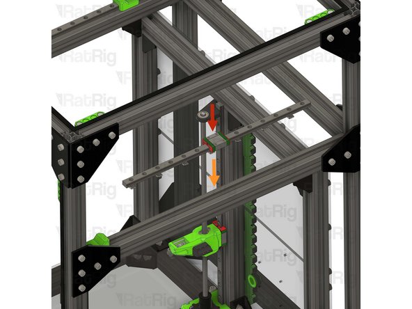
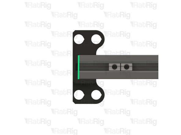
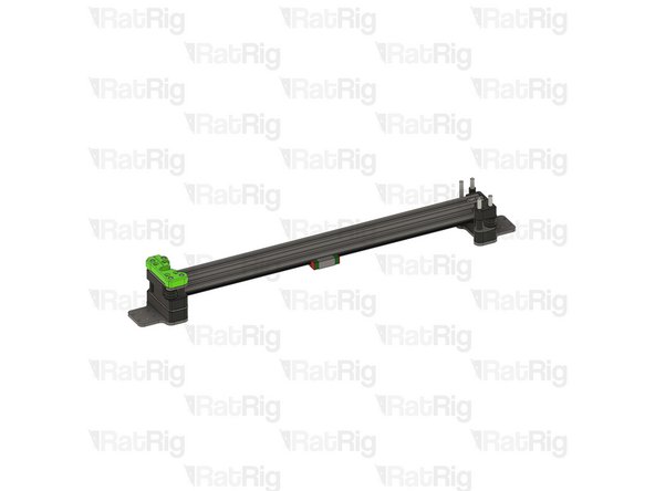
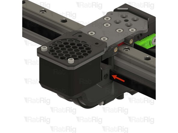
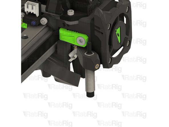
Y-axis linear rail assembly from step 36
-
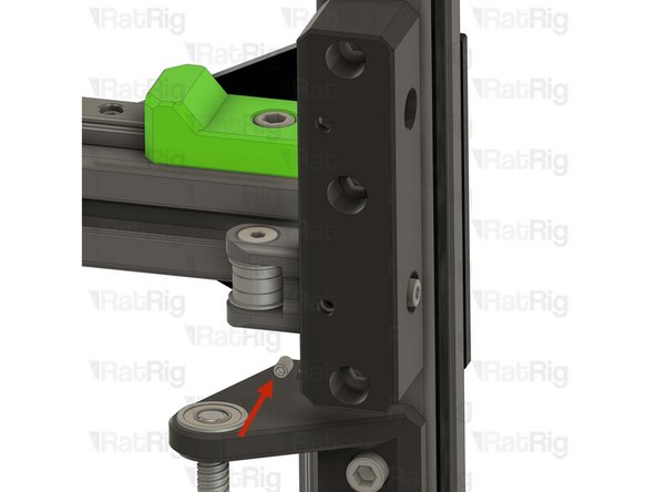
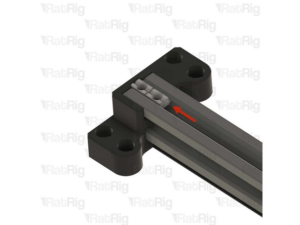
Sit the linear rail on top of the 3030, making sure all T-nuts drop into the extrusion slot
-
Install the two MGN12 3030 alignment tools as shown, this will make sure the linear rail is positioned correctly
-
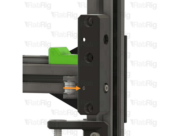
Slide the MGN12 linear rail into the Y bumper printed part
-
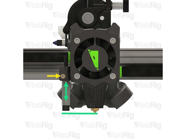
Fasten the marked M3x12 screws, starting from the front
-
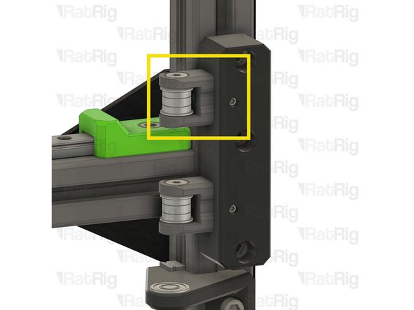
MGN12 Rails should be tightened to 98 N-cm of torque, overtightening the screws will result in rail binding
-
Remove the MGN12 3030 alignment tools
-
-
-
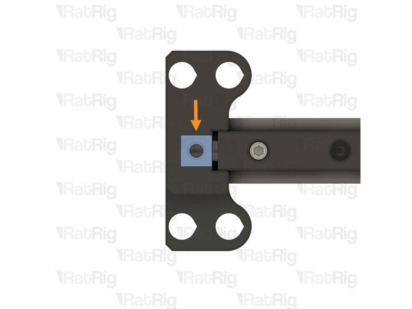
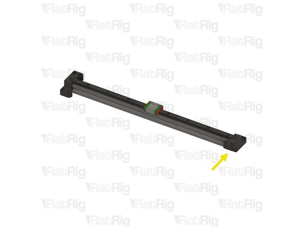
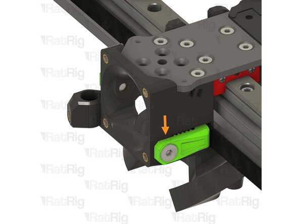
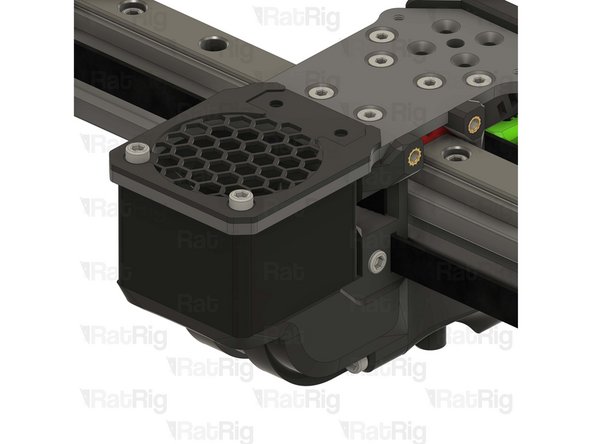
Y-max bumper assembly from step 61
-
Make sure the printed part is aligned with the linear rail and fully seated
-
Tighten the M6x12 Cap Head Screw
-
Do not overtighten the M6x12 Cap Head Screws as you damage the printed part
-
Repeat the previous 2 steps to install the second Y-axis linear rail and bumpers
-
-
-
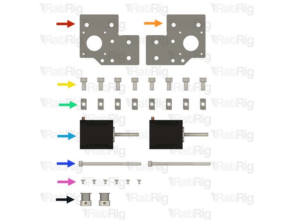
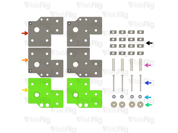
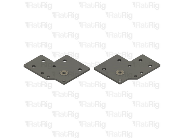
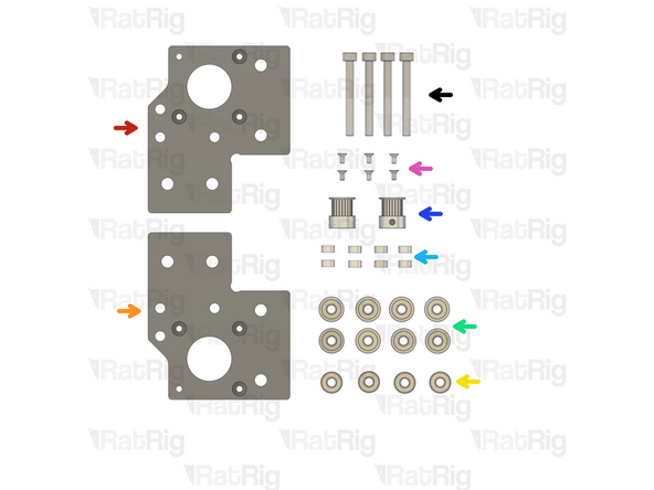
Rat Rig V-Core 4.0 - Motor Plate - Lower Right v1.0
-
Rat Rig V-Core 4.0 - Motor Plate - Lower Left v1.0
-
8x M6x12 Cap Head Screw
-
8x 3030 Drop-in T-nut M6
-
2x NEMA17 Stepper motor - HT - 48mm
-
2x M5x85 Cap Head Screws
-
6x M3x6 Countersink Screws
-
2x 20 Tooth 2GT Timing Pulley for 9mm Belt (Taken from the old CoreXY stepper motors)
-
-
-
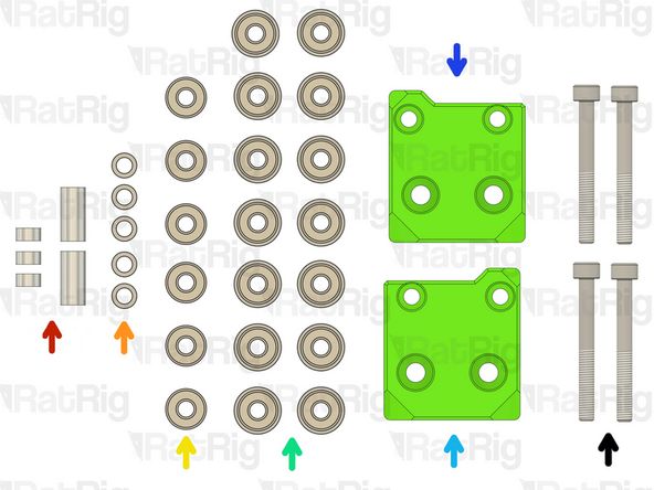
3x Aluminium spacer 5x8x4mm + 1x Aluminium spacer 5x8x14mm + 1x Aluminium spacer 5x8x17mm
-
5x Mini precision shim 8x5x1mm
-
6x Ball bearing 695ZZ
-
12x Ball bearing F695ZZ
-
Right vc4_motor_spacer
-
Left vc4_motor_spacer
-
4x M5x45 Cap Head Screws
-
-
-
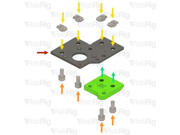
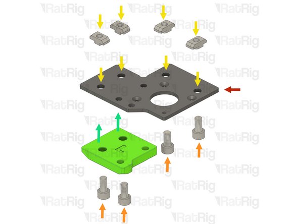
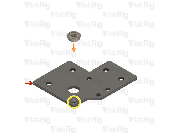
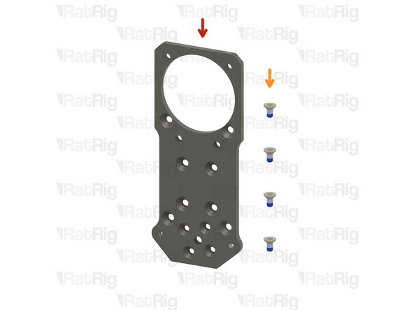
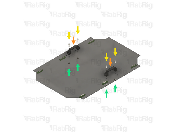
Rat Rig V-Core 4.0 - Motor Plate - Lower Right v1.0
-
4x M6x12 Cap Head Screw
-
4x 3030 Drop-in T-nut M6
-
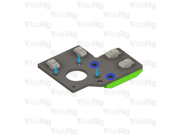
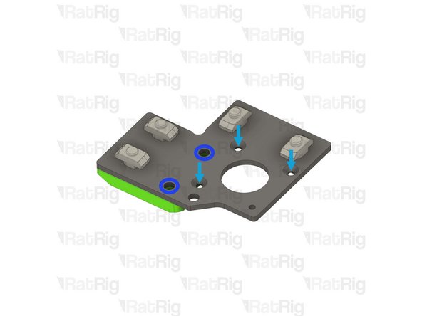
vc4_motor_spacer_right printed part
-
The T-nuts should be on the same side of the plate as the countersink holes
-
Loosely thread the 3030 T-nuts onto the M6x12 screws. Do not tighten them at this point
-
Install the printed part, making sure the holes are aligned
-
-
-
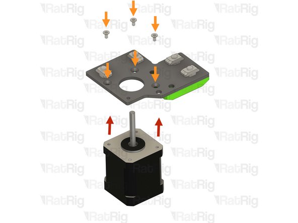
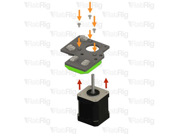
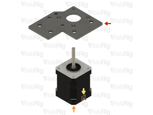
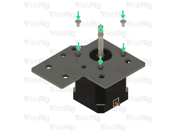
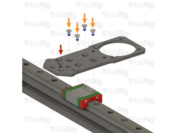
NEMA17 Stepper motor - HT - 48mm
-
3x M3x6 Countersink Screws
-
Make sure the cable from the stepper motor faces the direction shown in the image
-
Insert the M3x6 screws into the motor plate assembly as shown, and fasten them to secure the NEMA17 motor
-
-
-
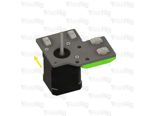
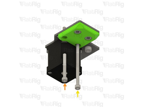
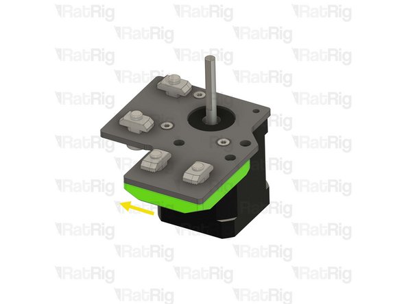
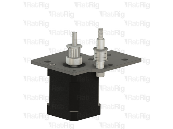
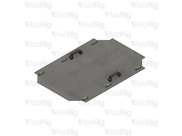
Ensure the vc4_motor_spacer_right printed part is aligned with the plate
-
Insert the M5x45 Cap Head Screw all the way
-
Insert the M5x85 Cap Head Screw all the way
-
Once inserted, the printed part should be able to hold them in place
-
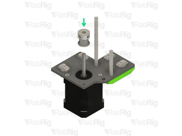
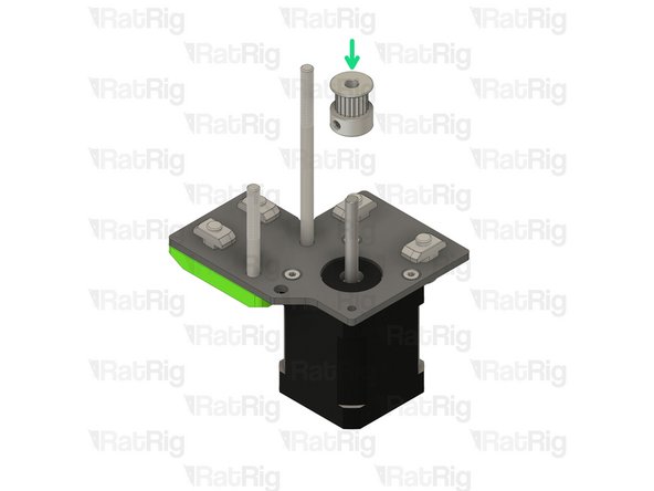
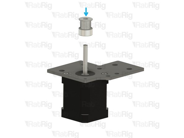
Install the timing pulley onto the NEMA17 shaft, oriented as shown
-
The timing pulley will be aligned and fully secured in a later step. Do not tighten the M3 set screws now
Once inserted, the printed part should be able to hold them in place.
And what should I do if the printed part doesn't hold them in place, especially when I get to the step where I'm installing this assembly?
-
-
-
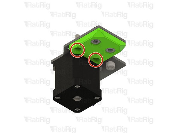
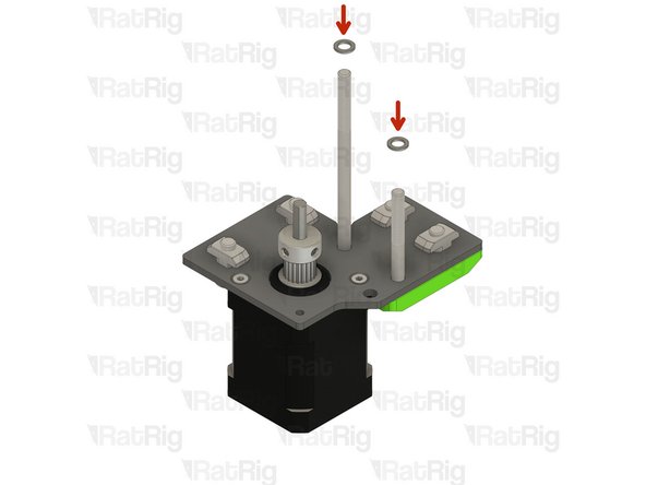
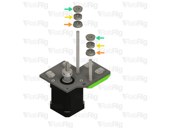
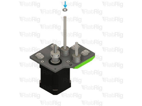
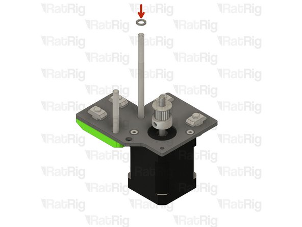
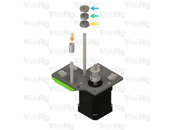
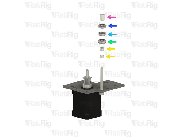
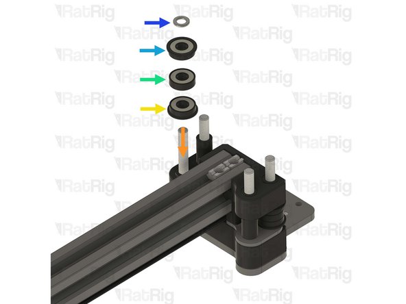
Install the following components in the order shown in the image:
-
Mini precision shim
-
F695ZZ Ball bearing (Flange at the bottom)
-
695ZZ Ball bearing
-
F695ZZ Ball bearing (Flange at the top)
-
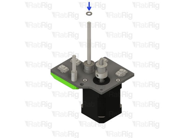
Install a Mini precision shim onto the rear M5x85 screw
-
-
-
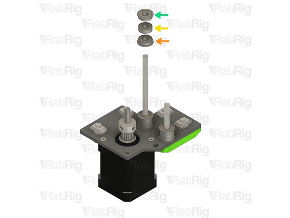
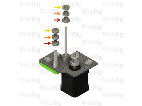
Install the following components onto the rear M5x85 screw in the order shown in the image:
-
F695ZZ Ball bearing (Flange at the bottom)
-
695ZZ Ball bearing
-
F695ZZ Ball bearing (Flange at the top)
-
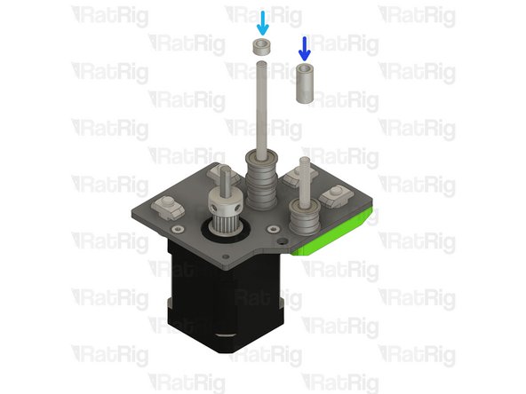
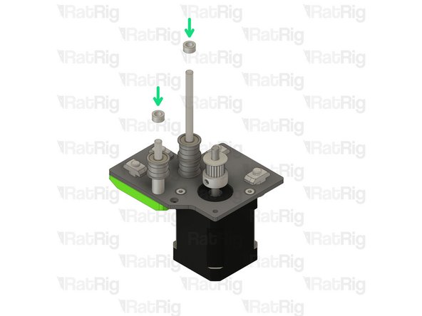
Install an Aluminium spacer 5x8x4mm onto the rear M5x85 Screw
-
Install an Aluminium spacer 5x8x17mm onto the front M5x45 Screw
-
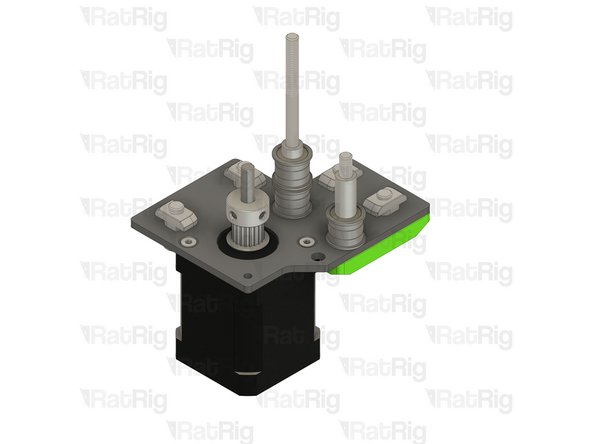
Set the assembly aside for now. it will be installed later in the guide
-
-
-
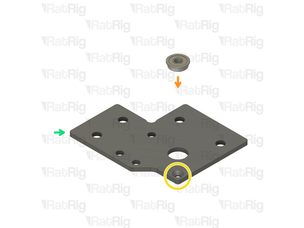
Rat Rig V-Core 4.0 - Motor Plate - Lower Left v1.0
-
4x M6x12 Cap Head Screw
-
4x 3030 Drop-in T-nut M6
-
vc4_motor_spacer_left printed part
-
The T-nuts should be on the same side of the plate as the countersink holes
-
Loosely thread the 3030 T-nuts onto the M6x12 screws. Do not tighten them at this point
-
Install the printed part, making sure the holes are aligned
-
-
-
NEMA17 Stepper motor - HT - 48mm
-
3x M3x6 Countersink Screws
-
Make sure the cable from the stepper motor faces the direction shown in the image
-
Insert the M3x6 screws into the motor plate assembly as shown, and fasten them to secure the NEMA17 motor
-
-
-
Ensure the vc4_motor_spacer_left printed part is aligned with the plate
-
Insert the M5x45 Cap Head Screw all the way
-
Insert the M5x85 Cap Head Screw all the way
-
Once inserted, the printed part should be able to hold them in place
-
Install the timing pulley onto the NEMA17 shaft, oriented as shown
-
The timing pulley will be aligned and fully secured in a later step. Do not tighten the M3 set screws now
-
-
-
Insert a mini precision shim onto the rear M5x85 screw
-
Install an aluminium spacer 5x8x14mm onto the front M5x45 screw
-
Install the following components onto the rear M5x85 screw in the order shown in the image:
-
F695ZZ Ball bearing (Flange at the bottom)
-
695ZZ Ball bearing
-
F695ZZ Ball bearing (Flange at the top)
-
Insert a mini precision shim onto the rear M5x85 screw
-
-
-
Install the following components in the order shown in the image:
-
F695ZZ Ball bearing (Flange at the bottom)
-
695ZZ Ball bearing
-
F695ZZ Ball bearing (Flange at the top)
-
Aluminium spacer 5x8x4mm
-
Set the assembly aside for now. it will be installed later in the guide
-
-
-
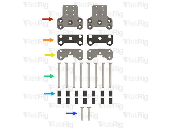
2x Rat Rig V-Core 4.0 - Motor Plate - Upper Right v1.0
-
2x Rat Rig V-Core 4.0 - Motor Plate - Upper Left v1.0
-
2x vc4_dual_motor_spacer printed part
-
4x Ball bearing F695ZZ
-
4x M5 Nylon locking nut
-
4x M3x40 Countersink Screw
-
4x Aluminium spacer 3x6x30mm
-
8x 3030 Drop-in T-nut - M6
-
-
-
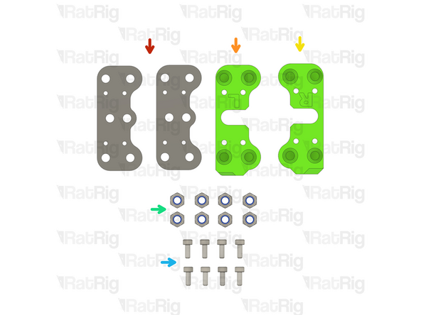
Rat Rig V-Core 4.0 - Motor Plate - Upper Right v1.0
-
Ball bearing F695ZZ
-
Ensure the bearing flange is on the same side as the countersink bore.
-
Assemble two of the upper right plates
-
Rat Rig V-Core 4.0 - Motor Plate - Upper Left v1.0
-
Repeat the above instructions to assemble two of the upper left plates
-
-
-
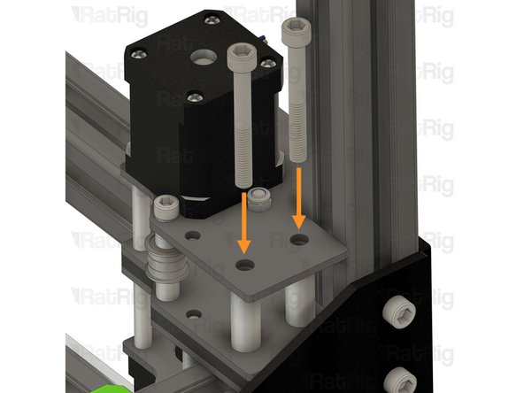
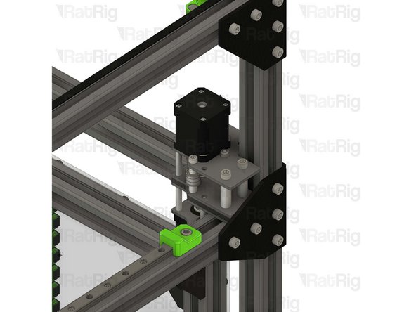
Place the right stepper motor assembly in the frame as shown
-
Make sure the plate is fully seated against the 3030 extrusion before the next step
-
-
-
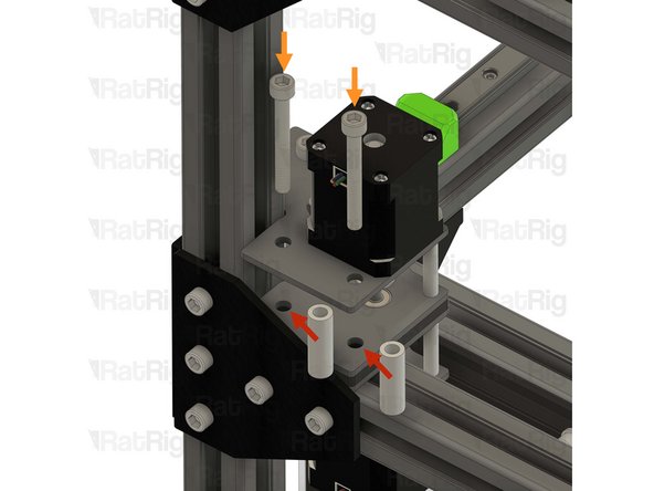
Tighten the four M6x12 screws to secure the stepper assembly to the frame
-
Do not overtighten the M6x12 Cap Head Screws in the printed part screws as you damage it
-
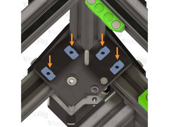
4x 3030 Drop-in T-nut - M6
-
Insert the T-nuts inside the extrusion slot as shown
-
-
-
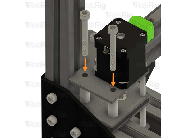
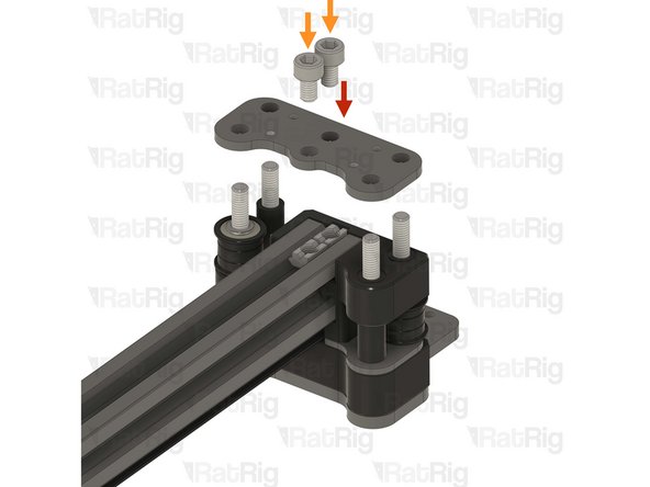
Upper right CoreXY plate assembly from step 78
-
Make sure the stepper motor shaft is aligned with the hole in the F695ZZ bearing
-
Insert the aluminium spacer 3x6x30mm between the top and bottom plates
-
Insert the M3x40 countersink screw through the top plate, the aluminium spacer and the bottom plate
-
Do not thread it to the stepper motor at this stage
-
-
-
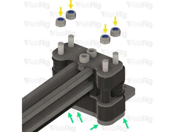
M5 Nylon locking nut
-
Thread the locking nut onto the M5x45mm Cap Head Screw
-
Hold the locking nut with the appropriate size wrench
-
Tighten the M5x45mm Cap Head Screw
-
Ensure the bearings rotate freely
-
Tighten the M3x40 Countersink Screw
-
-
-
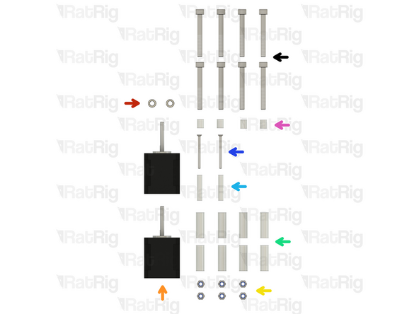
-
1x Rat Rig V-Core 4.0 - Motor Plate - Lower Right v1.0
-
1x Rat Rig V-Core 4.0 - Motor Plate - Lower Left v1.0
-
4x Ball bearing 695ZZ
-
8x Ball bearing F695ZZ
-
8x Aluminium spacer 5x8x4mm
-
2x 20 Tooth 2GT Timing Pulley for 9mm Belt
-
6x M3x6 Countersink Screw
-
4x M5x45 Cap Head Screw
-
-
-
2x Mini precision shim 8x5x1mm
-
2x NEMA17 Stepper motor - HT - 48mm
-
6x M5 Nylon locking nut
-
8x Aluminium spacer 6x10x30mm
-
2x Aluminium spacer 3x6x30
-
2x M3x40 CounterSink Screw
-
4x Aluminium Spacer 5x8x10mm
-
8x M6x50 Cap Head Screw
-
-
-
1x Rat Rig V-Core 4.0 - Motor Plate - Lower Left v1.0
-
Despite being the right stepper, this plate is the left variant
-
NEMA17 Stepper motor - HT - 48mm
-
Make sure the cable from the stepper motor faces the direction shown in the image
-
3x M3x6 Countersink Screw
-
Insert the M3x6 screws into the motor plate as shown, and fasten them to secure the NEMA17 motor
-
20 Tooth 2GT Timing Pulley for 9mm Belt
-
The timing pulley will be aligned and fully secured in a later step. Do not tighten the M3 set screws now
-
-
-
M5x45 Cap Head Screw
-
Install a mini precision shim on the screw, before installing it on the plate
-
Install the following components in the order shown in the image:
-
2x Aluminium spacer 5x8x4mm
-
F695ZZ Ball bearing (Flange at the bottom)
-
695ZZ Ball bearing
-
F695ZZ Ball bearing (Flange at the top)
-
Aluminium spacer 5x8x10mm
-
-
-
Rat Rig V-Core 4.0 - Motor Plate - Upper Left assembly from step 78
-
Aluminium spacer 3x6x30mm
-
Insert the aluminium spacer between the top and bottom plates
-
M3x40 Countersink Screw
-
Insert the M3x40 countersink screw through the top plate, the aluminium spacer and the bottom plate. Loosely thread it into the stepper motor but do not tighten it at this point
-
Ensure the screw head is on the same side as the countersunk hole
-
M5 Nylon locking nut
-
Thread the locking nut onto the M5x45mm Cap Head Screw
-
-
-
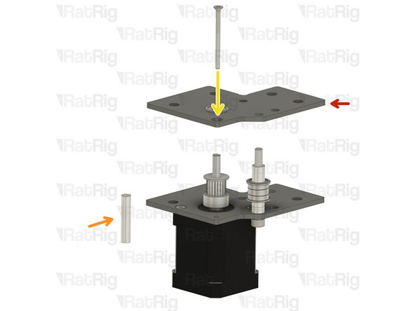
M5x45 Cap Head Screw
-
Insert the screw into the marked hole and push it in 5-10mm
-
Insert the following items while pushing the M5x45 Cap head screw further:
-
Aluminium spacer 5x8x4mm
-
Insert the M5x45 further
-
Aluminium spacer 5x8x4mm
-
Insert the M5x45 further
-
F695ZZ Ball bearing (Flange at the bottom)
-
-
-
Insert the following items while pushing the M5x45 Cap head screw further:
-
695ZZ Ball bearing
-
Insert the M5x45 further
-
F695ZZ Ball bearing (Flange at the top)
-
Insert the Aluminium spacer 5x8x10mm
-
Fully insert the M5x45mm Cap Head Screw
-
Do not allow it to drop out
-
-
-
Flip the assembly upside down, making sure the M5x45 Cap Head Screw does not fall out
-
Tighten the M3 Countersink screw
-
Tighten the M5 Nylon locking nut
-
Put the assembly aside, it will be used later in the guide
-
-
-
1x Rat Rig V-Core 4.0 - Motor Plate - Lower Right v1.0
-
Despite being the left stepper, this plate is the right variant
-
NEMA17 Stepper motor - HT - 48mm
-
Make sure the cable from the stepper motor faces the direction shown in the image
-
3x M3x6 Countersink Screws
-
Insert the M3x6 screws into the motor plate as shown, and fasten them to secure the NEMA17 motor
-
20 Tooth 2GT Timing Pulley for 9mm Belt
-
The timing pulley will be aligned and fully secured in a later step. Do not tighten the M3 set screws now
-
-
-
M5x45 Cap Head Screw
-
Install a mini precision shim on the screw, before installing it on the plate
-
Install the following components in the order shown in the image:
-
2x Aluminium spacer 5x8x4mm
-
F695ZZ Ball bearing (Flange at the bottom)
-
695ZZ Ball bearing
-
F695ZZ Ball bearing (Flange at the top)
-
Aluminium spacer 5x8x10mm
-
-
-
Rat Rig V-Core 4.0 - Motor Plate - Upper Left assembly from step 78
-
Aluminium spacer 3x6x30mm
-
Insert the aluminium spacer between the top and bottom plates
-
M3x40 Countersink Screw
-
Insert the M3x40 countersink screw through the top plate, the aluminium spacer and the bottom plate. Loosely thread it into the stepper motor but do not tighten it at this point
-
Ensure the screw head is on the same side as the countersunk hole
-
M5 Nylon locking nut
-
Thread the locking nut onto the M5x45mm Cap Head Screw
-
-
-
M5x45 Cap Head Screw
-
Insert the screw into the marked hole and push it in 5-10mm
-
Insert the following items while pushing the M5x45 Cap head screw further:
-
Aluminium spacer 5x8x4mm
-
Insert the M5x45 further
-
Aluminium spacer 5x8x4mm
-
Insert the M5x45 further
-
F695ZZ Ball bearing (Flange at the bottom)
-
-
-
Insert the following items while pushing the M5x45 Cap head screw further:
-
695ZZ Ball Bearing
-
Insert the M5x45 further
-
F695ZZ Ball Bearing (Flange at the top)
-
Insert the Aluminium spacer 5x8x10mm
-
Fully insert the M5x45mm Cap Head Screw
-
Do not allow it to drop out
-
-
-
Flip the assembly upside down, making sure the M5x45 Cap Head Screw does not fall out
-
Tighten the M3 Countersink screw
-
Tighten the M5 Nylon locking nut
-
Put the assembly aside, it will be used later in the guide
-
-
-
vc4_dual_motor_spacer
-
Install the printed part on the screws
-
Make sure the T-nuts in the 3030 extrusion slot are aligned with the printed part holes, this will be critical in the next steps. You can use a small hex key to help align them
-
Right hybrid stepper motor assembly from step 91
-
Make sure the assembly is flush with the frame extrusion before proceeding
-
-
-
Align the M5x85 Cap Head Screw already on the V-Core 3.2H, with the M5x45 Cap Head Screw on the right hybrid stepper motor assembly
-
Slowly lower the right hybrid stepper motor assembly
-
While allowing the M5x85 Screw to push the M5x45 screw out
-
Take it slowly, as it is crucial all components get transferred to the M5x85 Cap Head Screw
-
Completely remove the M5x45 Cap Head Screw, it will not be used anymore
-
-
-
Make sure the right hybrid stepper motor assembly is fully seated on the printed part
-
M5 Nylon locking nut
-
Hold the locking nut with the appropriate size wrench
-
Thread the M5x85 Cap Head Screw into the M5 Nylon locking nut
-
Do not fully tighten it yet, it will be tightened later in the guide
-
Verify that all T-nuts are aligned with the holes in the right hybrid stepper motor assembly
-
You can use a small hex key to help align them
-
-
-
2x Aluminium spacer 6x10x30mm
-
Insert the spacers between the plates and align them with the holes
-
2x M6x50 Cap Head Screws
-
Insert the screws through the top plate, spacers, and bottom plate, threading them into the previously inserted M6 T-nuts
-
Do not fully tighten the M6x50 screws yet
-
-
-
M5 Nylon locking nut
-
Hold the locking nut with the appropriate size wrench
-
Tighten the M5x85 Cap Head Screw
-
Ensure the bearings rotate freely
-
Tighten all the M6x50 screws to secure the assembly to the frame
-
-
-
-
vc32h_tensioner_body_left printed part
-
vc32h_tensioner_body_right printed part
-
6x M6x16 cap head screw
-
6x 3030 Drop-in T-nut - M6
-
4x M4x20 cap head screw
-
4x Hex nut - M4
-
4x M4x6 set screw
-
4x Washer - M4
-
-
-
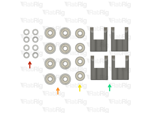
8x Mini precision shim 8x5x1mm
-
8x Ball bearing F695ZZ
-
4x Ball bearing 695ZZ
-
4x Rat Rig V-Core 4.0 - Tensioner Arm v1.0
-
-
-
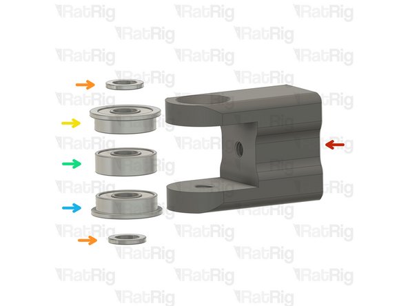
Rat Rig V-Core 4.0 - Tensioner Arm v1.0
-
Install the following components in the order shown in the image:
-
Mini precision shim
-
F695ZZ ball bearing (Flange at the top)
-
695ZZ ball bearing
-
F695ZZ ball bearing (Flange at the bottom)
-
Mini precision shim
-
-
-
Insert the M5x22 countersink screw and tighten it to secure the idler assembly into the tensioner arm
-
Repeat the previous step, and this step to assemble another three tensioner arms
-
-
-
3x M6x16 cap head screws
-
vc32h_tensioner_body_right printed part
-
3x 3030 Drop-in T-nut - M6
-
Insert the M6x16 screws into the tensioner body as shown, then loosely thread a 3030 T-nut onto each of the M6x16 screws. Do not tighten them at this point
-
Align the tensioner body with the extrusion slot and partially tighten the middle M6x16 screw temporarily
-
Position the tensioner body alignment tool, as shown
-
Loosen the middle M6x16 screw and align the tensioner body so the bottom is sat on the alignment tool
-
Tighten all 3 M6x16 screws and remove the alignment tool
-
-
-
1x Hex nut - M4
-
Insert the hex nut into the hexagonal hole inside the tensioner body before installing the tensioner arms
-
-
-
Front tensioner arm assembly
-
Insert the tensioner arm in the lower slot of the tensioner body as shown
-
Make sure the tensioner arm has cleared the hole on the tensioner body.
-
M4x20 cap head screw + M4 washer
-
Insert the screw through the tensioner body and lightly thread it to the tensioner arm.
-
The M4x20 screw must be partially, but not fully, threaded into the tensioner arm. This allows the largest possible range for tensioning the belts further in the guide
-
-
-
M4x6 Set screw
-
Gently tighten the set screw to secure the tensioner arm in place
-
Overtightening the set screws will damage the printed tensioner bodies
-
Repeat the previous 2 steps, and this step, to install the top tensioner arm
-
-
-
-
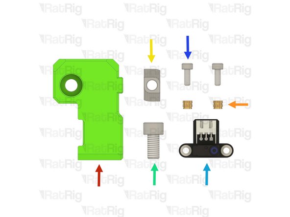
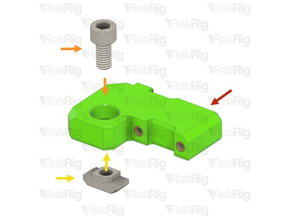
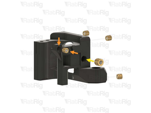
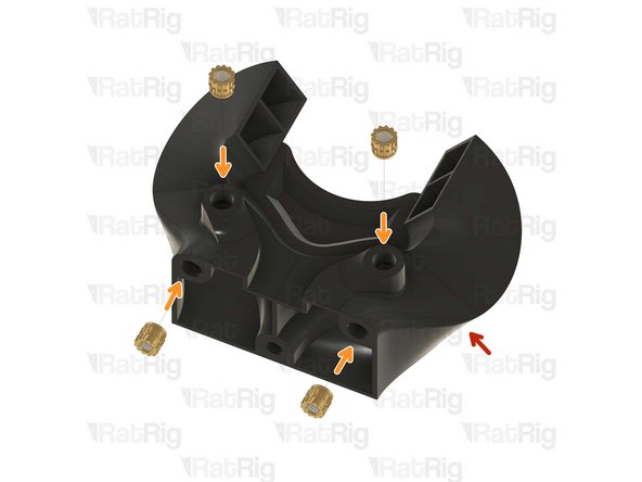
1x vc32h_y_endstop_mount printed part
-
2x M3 Heat insert
-
1x 3030 Drop-in T-nut - M6
-
1x M6x12 cap head screw
-
1x Rat Rig Endstop
-
2x M3x8 cap head screw
-
-
-
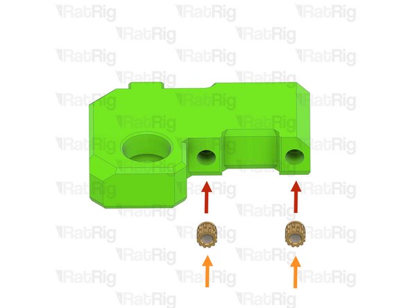
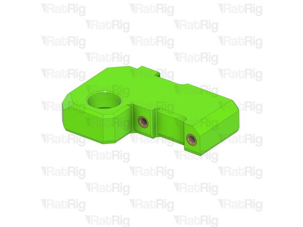
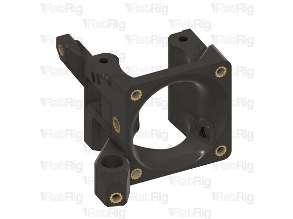
1x vc32h_y_endstop_mount
-
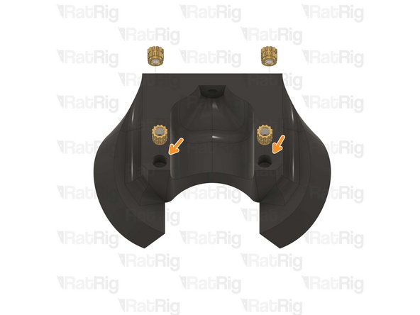
2x M3 Heat insert
-
Use a soldering iron with a heat insert tip to install the M3 heat inserts into the printed part as shown
-
Rat Rig printed parts are made from ABS, it is recommended to set your soldering iron to 265°C to install the heat inserts
-
Do not use a temperature higher than 280C as this can cause the ABS to release harmful fumes
-
Take care not to burn yourself
-
-
-
1x Prepared vc32h_y_endstop_mount
-
2x M6x12 cap head screw
-
Install the M6 cap head screw into the Y endstop mount as shown
-
1x 3030 Drop-in T-nut - M6
-
Loosely thread the 3030 T-nut onto the M6x12 screw. Do not tighten it at this point
-
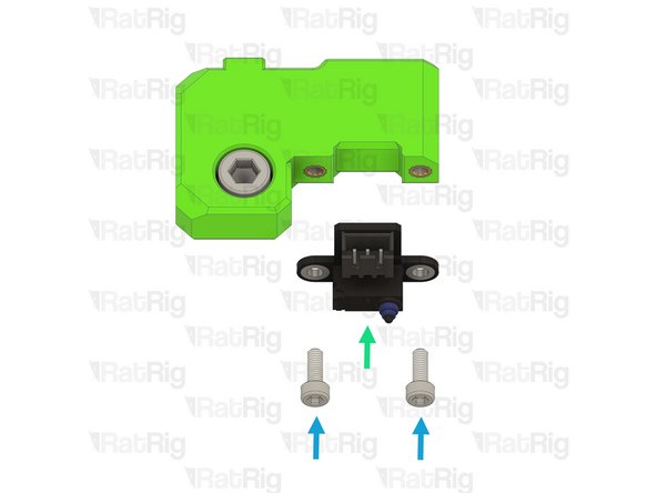
Rat Rig Endstop
-
2x M3x8 Cap Head Screw
-
Tighten the M3x8 screws to secure the endstop to the printed part. Do not overtighten them as you can damage the endstop or printed part
-
-
-
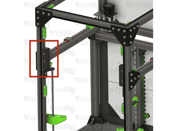
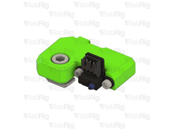
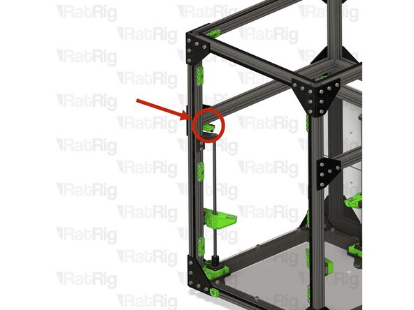
Y-axis endstop mount assembly from the previous step
-
Install the Y endstop mount assembly to the left side of the V-Core 3 frame as shown
-
Tighten the M6x12 screw to secure the Y endstop mount
-
Do not overtighten the M6x12 Cap Head Screw as you can damage the printed part
-
-
-
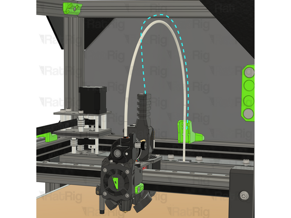
1x vc32h_umbilical_frame printed part
-
2x M6x12 cap head screw
-
2x 3030 Drop-in T-nut - M6
-
-
-
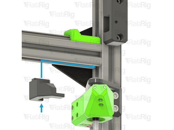
vc_32h_umbilical_guide printed part
-
2x M6x12 cap head screws
-
2x 3030 Drop-in T-nut - M6
-
Insert the M6x12 screws into the printed as shown, then loosely thread a 3030 T-nut onto each of the M6x12 screws. Do not tighten them at this point
-
Install the toolhead umbilical guide assembly to the frame as shown
-
Check that the guide is in the middle of the frame
-
Tighten the two M6x12 screws to secure the guide to the frame
-
Do not overtighten the M6x12 Cap Head Screws as you can damage the printed part
-
-
-
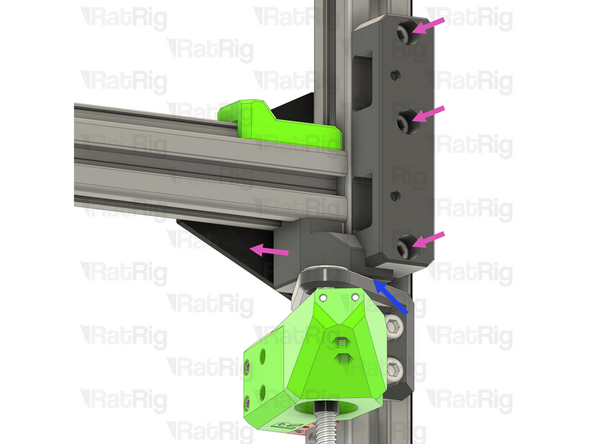
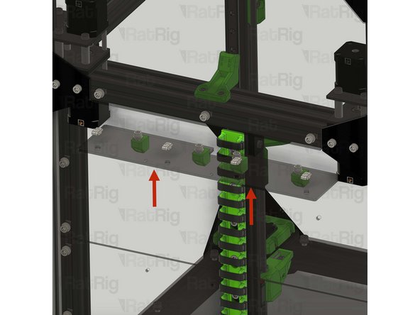
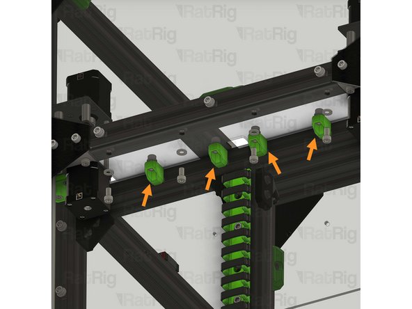
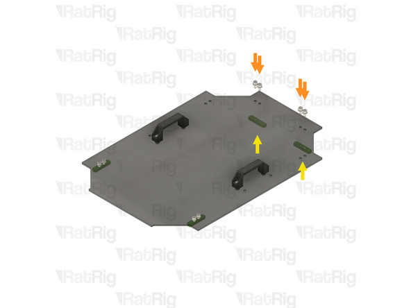
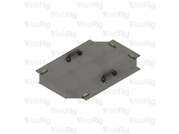
Insert the rear shelf assemblies one at a time
-
The M6 cap head screws should fit inside the shelf_support printed parts
-
Tighten the M6x12 cap head screws to secure the shelves to the frame
-
Do not overtighten the M6x12 Cap Head Screws as you crack the shelves
-
-
-
2x vc4_xy_joiner_upper plate
-
2x vc4_x_endstop printed part
-
2x vc32h_xy_joiner_middle plate
-
8x M5x60 countersink screw
-
14x Aluminium spacer 5x8x14mm
-
2x M5x30 low profile screw
-
-
-
2x vc32h_xy_spacer printed part
-
4x Ball bearing 695ZZ
-
8x Ball bearing F695ZZ
-
4x Mini precision shim 8x5x1mm
-
4x Aluminium spacer 5x8x27mm
-
-
-
2x Rat Rig V-Core 4.0 - XY Joiner - Lower v1.1
-
1x vc4_xy_trim_left printed part
-
1x vc4_xy_trim_right printed part
-
8x M5 Nylon locking nut
-
8x M3x8 Cap Head Screw
-
-
-
vc4_xy_joiner_upper plate
-
4x M5x60 Countersink screw
-
M5x30 Low profile screw
-
Insert the screws into the plate, in the positions shown, and then flip the assembly upside down
-
-
-
5x Aluminium spacer 5x8x14mm
-
Places one aluminium spacer onto each screw
-
vc4_x_endstop printed part
-
Align the printed part with the screws and spacers, pushing it down fully. The aluminium spacers will fit inside the printed part
-
vc32h_xy_joiner_middle plate
-
Align the plate and with the screws and set it on top of the printed part
-
-
-
Install the following components, onto the marked screw, in the order shown in the image:
-
Mini precision shim
-
F695ZZ Ball bearing (Flange at the bottom)
-
695ZZ Ball bearing
-
F695ZZ Ball bearing (Flange at the top)
-
Aluminium spacer 5x8x27mm
-
Aluminium spacer 5x8x14mm
-
Insert the aluminium spacers onto the marked screws
-
-
-
4x M5x8 cap head screw
-
6x T-nut M5 square type for 2020
-
X-axis linear rail and 2020 aluminium profile assembly from step 51
-
-
-
Place the X-axis linear rail and 2020 aluminium profile assembly upside down, with the MGN12 carriage on a flat surface
-
Insert two of the T-nuts into the top extrusion slot
-
Insert one of the T-nuts into the bottom extrusion slot
-
Gently install the vc32h_xy_spacer onto the end of the 2020 extrusion in the orientation shown
-
The two square T-nuts must be facing the opening on the printed part
-
Ensure the printed part, and the end of the extrusion, are flush
-
-
-
Push the two T-nuts to the end of the extrusion slot, so they touch the printed part
-
Flip the assembly upside down, and push the single T-nut underneath the printed part, ensuring it is aligned with the hole in the printed part
-
Repeat the previous step, and this step, to prepare the other end of the assembly
-
-
-
Take the assembly from the previous step and install the printed part onto the aluminium spacers of the left joiner from step 126
-
Install the following components onto the marked screw, in the order shown in the image:
-
F695ZZ Ball bearing (Flange at the bottom)
-
695ZZ Ball bearing
-
F695ZZ Ball bearing (Flange at the top)
-
Mini precision shim
-
-
-
Rat Rig V-Core 4.0 - XY Joiner - Lower v1.1
-
2x M5x8 Cap Head Screw
-
Insert the screws through the plate, and tighten them into the T-nuts within the 2020 extrusion
-
4x M5 Nylon locking nut
-
Thread an M5 Nylon locking nut onto each of the M5x60 countersink screws
-
Tighten all four M5x60 countersink screws, using an appropriately sized wrench
-
Do not overtighten the screws, as too much force can cause the gantry to bind when installed on the V-Core 3.2H
-
-
-
vc4_xy_trim_left printed part
-
4x M3x8 Cap Head Screw
-
Insert the screws through the printed part and tighten them to secure the printed part to the plate
-
-
-
Tighten the marked screw to secure the gantry to the joiner
-
Before proceeding: Verify your assembly against the provided image to make sure your assembly is correct
-
-
-
vc4_xy_joiner_upper plate
-
M5x60 Countersink screw
-
M5x30 Low profile screw
-
Insert the screws into the plate, in the positions shown, and then flip the assembly upside down
-
-
-
5x Aluminium spacer 5x8x14mm
-
Places one aluminium spacer onto each screw
-
vc4_x_endstop printed part
-
Align the printed part with the screws and spacers, pushing it down fully. The aluminium spacers will fit inside the printed part
-
vc32h_xy_joiner_middle plate
-
Align the plate and with the screws and set it on top of the printed part
-
-
-
Install the following components, onto the marked screw, in the order shown in the image:
-
Mini precision shim
-
F695ZZ Ball bearing (Flange at the bottom)
-
695ZZ Ball bearing
-
F695ZZ Ball bearing (Flange at the top)
-
Aluminium spacer 5x8x27mm
-
Aluminium spacer 5x8x14mm
-
Insert the aluminium spacers onto the marked screws
-
-
-
Take the X-axis gantry assembly from step 133 and install the printed part onto the aluminium spacers of the right joiner from the previous step
-
Install the following components onto the marked screw, in the order shown in the image:
-
F695ZZ Ball bearing (Flange at the bottom)
-
695ZZ Ball bearing
-
F695ZZ Ball bearing (Flange at the top)
-
Mini precision shim
-
-
-
Rat Rig V-Core 4.0 - XY Joiner - Lower v1.1
-
2x M5x8 Cap Head Screw
-
Insert the screws through the plate, and tighten them into the T-nuts within the 2020 extrusion
-
4x M5 Nylon locking nut
-
Thread an M5 Nylon locking nut onto each of the M5x60 countersink screws
-
Tighten all four M5x60 countersink screws, using an appropriately sized wrench
-
Do not overtighten the screws, as too much force can cause the gantry to bind when installed on the V-Core 3.2H
-
-
-
vc4_xy_trim_left printed part
-
4x M3x8 Cap Head Screw
-
Insert the screws through the printed part and tighten them to secure the printed part to the plate
-
Tighten the marked screw to secure the gantry to the joiner
-
Set the assembly aside for now. it will be installed later in the guide
-
-
-
8x M3x8 Cap Head Screw with blue thread lock
-
The plastic bag has a BT label
-
8x M3 Washer
-
-
-
V-Core 3.2H Frame Assembly
-
X-Axis gantry assembly
-
Carefully insert the gantry assembly into the V-Core 3 frame from the side, as shown
-
Place the XY joiners on each end of the X-axis gantry, on top of the Y-axis linear rail carriages
-
When installing, keep the left and right orientation of the gantry in mind. Installing it in reverse will prevent correct installation of the belts
-
-
-
4x M3x8 Cap Head Screw
-
4x M3 washer
-
Install an M3 washer onto each M3x8 Cap Head Screw, then into the marked holes in the XY joiner plates
-
Tighten the M3 screws to secure the XY joiner to the Y-axis linear rail carriage
-
Do not overtighten the screws, as this can cause the gantry to bind in the Y direction
-
-
-
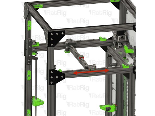
Test the movement of the Y-axis over the full travel distance
-
Small changes in resistance are normal, but becoming much harder to push, or binding completely, are not
-
If the gantry feels hard to push, you can loosen the M3x8 Cap Head Screws installed on the previous steps a quarter of a turn
-
Make sure there is no play between the joiner plates and the linear rail carriages if you loosen the M3x8 Cap Head Screws
-
-
-
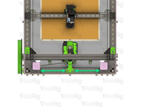
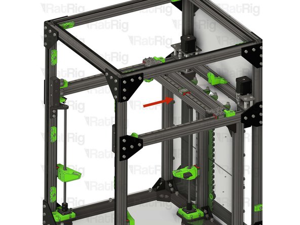
Move the X-axis gantry to the front of the machine
-
Both XY joiners should touch the Y-axis bumpers at the same time
-
This shows an exaggerated example of a misaligned gantry. The left side has a gap between the XY joiner and Y-axis bumper, and the right side has already touched the bumper
-
If your gantry is not bumping into both printed parts at the same time, follow the next steps:
-
Loosen the middle screw in the top of each XY joiner
-
Loosen the two M6x12 screws in the underside of each XY joiner
-
Push both XY joiners against the Y-axis bumpers by hand
-
Retighten all six screws which were loosened, then return to the previous step to check the Y-axis movement
-
-
-
Find the belt package labelled HW4225GC - Timing Belt - GATES - 2GT 9mm (6 meters pack) from the pack labelled HW4137MK - Rat Rig V-Core 3.2H - Hardware Pack B - Mechanical
-
Unroll the belt and cut it exactly in half, giving 2x three metre lengths
-
Make sure you cut the correct belt. There are two provided, the second one, HW4226GC - Timing Belt - GATES - 2GT 9mm (3.2 meters pack), will be used later in the guide
-
-
-
This step is not mandatory, it is just a Rat Rig tip on how to feed the belts on the idlers
-
Zip Tie
-
The wider the zip tie is, the easier the process will be
-
Bend the tip of the zip tie a little bit and feed it between the joiner assembly and the idler, as shown
-
Insert the belt between the zip tie and the idler
-
Slowly feed the belt and pull the zip tie at the same time
-
-
-
Ensure the belt teeth are facing the stepper motor pulleys
-
Take one end of the lower CoreXY belt, and feed it as shown:
-
Feed the belt through the left stepper motor bearing stacks
-
Feed the belt around the rear bearing stack on the left XY joiner
-
Take the other end of the lower CoreXY belt, and feed it as shown:
-
Feed the belt through the right stepper motor bearing stacks
-
Feed the belt behind the right XY joiner, through the bottom arm on the front right tensioner, and finally the front bearing stack on the right XY joiner
-
Do not cut any excess belt at this stage
-
-
-
Ensure the belt teeth are facing the stepper motor pulleys
-
Take one end of the upper CoreXY belt, and feed it as shown:
-
Feed the belt through the left stepper motor bearing stacks
-
Feed the belt behind the left XY joiner, through the bottom arm on the front left tensioner, and finally the front bearing stack on the left XY joiner
-
Take the other end of the upper CoreXY belt, and feed it as shown:
-
Feed the belt through the right stepper motor bearing stacks
-
Feed the belt around the rear bearing stack on the left XY joiner
-
Do not cut any excess belt at this stage
-
-
-
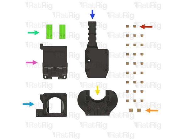
26x Heat Insert M3
-
2x Heat Insert M4
-
1x rr_vc4_toolhead_duct printed part
-
2x rr_vc4_toolhead_back_clamp printed part
-
1x rr_vc4_toolhead_front printed part
-
1x rr_vc4_toolhead_toolboard_vertical printed part
-
1x rr_vc32h_toolhead_back printed part
I recommend making the following modification to the toolhead, to resolve issues with filament feeding at the extruder:
"Rat Rig V-Core 4 PTFE tube support for Smart Sensor for Orbiter v2"
From "Teo" on printables.
This mod fixes the problem caused by the following error message:
RatOS: Filament clog or tangle detected on T0!
-
-
-
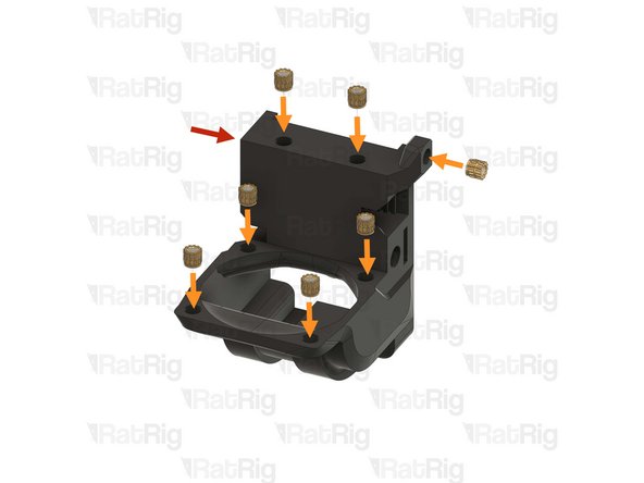
1x rr_vc32h_toolhead_back printed part
-
8x M3 Heat insert
-
Use a soldering iron with a heat insert tip to install the M3 heat inserts into the printed part as shown
-
Rat Rig printed parts are made from ABS, it is recommended to set your soldering iron to 265°C to install the heat inserts
-
Do not use a temperature higher than 280C as this can cause the ABS to release harmful fumes
-
Take care not to burn yourself
-
-
-
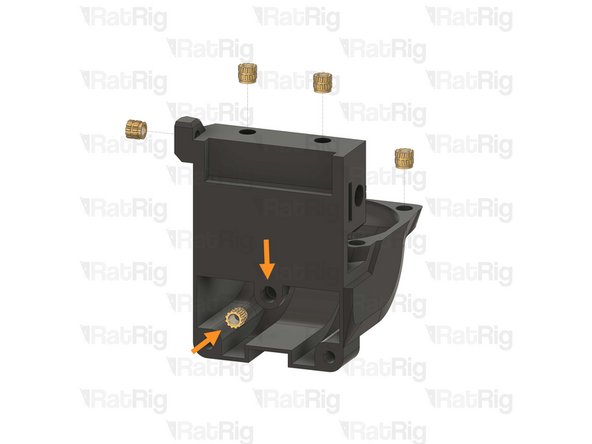
1x rr_vc4_toolhead_front
-
6x M3 Heat insert
-
Use a soldering iron with a heat insert tip to install the M3 heat inserts into the printed part as shown
-
2x M4 Heat insert
-
Use a soldering iron with a heat insert tip to install the M4 heat inserts into the printed part as shown
-
Rat Rig printed parts are made from ABS, it is recommended to set your soldering iron to 265°C to install the heat inserts
-
Do not use a temperature higher than 280C as this can cause the ABS to release harmful fumes
-
Take care not to burn yourself
-
-
-
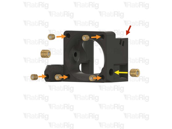
1x rr_vc4_toolhead_duct
-
6x M3 Heat insert
-
Use a soldering iron with a heat insert tip to install the M3 heat inserts into the printed part as shown
-
Rat Rig printed parts are made from ABS, it is recommended to set your soldering iron to 265°C to install the heat inserts
-
Do not use a temperature higher than 280C as this can cause the ABS to release harmful fumes
-
Take care not to burn yourself
-
-
-
1x rr_vc4_toolhead_toolboard_vertical
-
4x M3 Heat insert
-
Use a soldering iron with a heat insert tip to install the M3 heat inserts into the printed part as shown
-
Rat Rig printed parts are made from ABS, it is recommended to set your soldering iron to 265°C to install the heat inserts
-
Do not use a temperature higher than 280C as this can cause the ABS to release harmful fumes
-
Take care not to burn yourself
-
-
-
Clean the sacrificial layers on the rr_vc4_toolhead_back_clamp parts, obtaining a clean passthrough hole
-
It is recommended to remove the sacrificial layers by using a correctly sized drill, screwdriver, or hex key
-
2x rr_vc4_toolhead_back_clamp
-
2x Heat Insert M3
-
Use a soldering iron with a heat insert tip to install the M3 heat inserts into the printed part as shown
-
Rat Rig printed parts are made from ABS, it is recommended to set your soldering iron to 265°C to install the heat inserts
-
Do not use a temperature higher than 280C as this can cause the ABS to release harmful fumes
-
Take care not to burn yourself
-
-
-
1x Rat Rig Toolhead Plate - V-Core - v1.0 (Orbiter/Rapido)
-
4x M3x6 Countersink Screw with thread lock
-
-
-
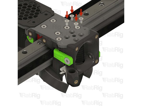
Rat Rig Toolhead Plate - V-Core - v1.0 (Orbiter/Rapido)
-
4x M3x6 Countersink Screw
-
Tighten the M3x6 Countersink Screws to secure the plate to the carriage
-
Pay attention to the orientation of the toolhead plate. The pointed end must face the front of the printer, with the countersink holes facing upwards
-
Avoid using a ball-end hex key, as they are more prone to damaging, or stripping, the M3 Countersink Screw heads
-
After tightening the screws, it is essential to verify that the X carriage retains its free movement. Excessive tightening of the screws may lead to the binding of the carriage
-
-
-
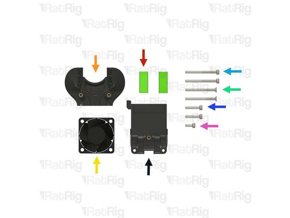
-
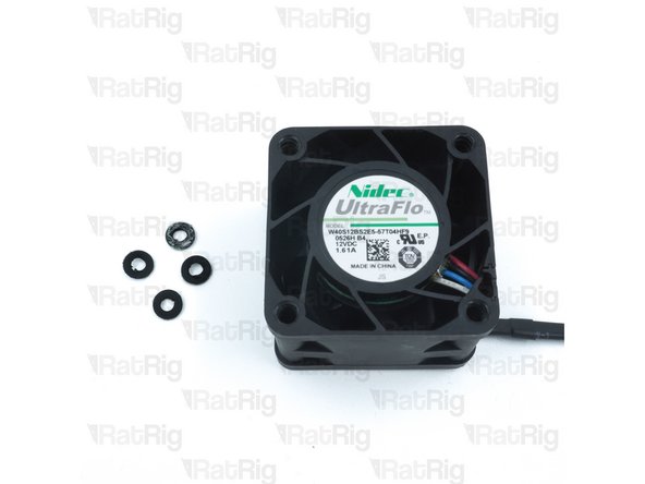
Make sure the 4028 part cooling fan does not have the four rubber spacers installed
-
If the rubber spacers are present, remove them
-
-
-
Prepared rr_vc32h_toolhead_back from step 151
-
Prepared rr_vc4_toolhead_duct from step 153
-
2x M3x16 Cap Head Screw
-
Insert the M3x16 screws through the toolhead back and tighten them into the duct
-
1x M3x8 Cap Head Screw
-
Insert the M3x8 screw through the duct and tighten it into the toolhead back
-
Do not overtighten the screws as you can damage the printed parts
-
-
-
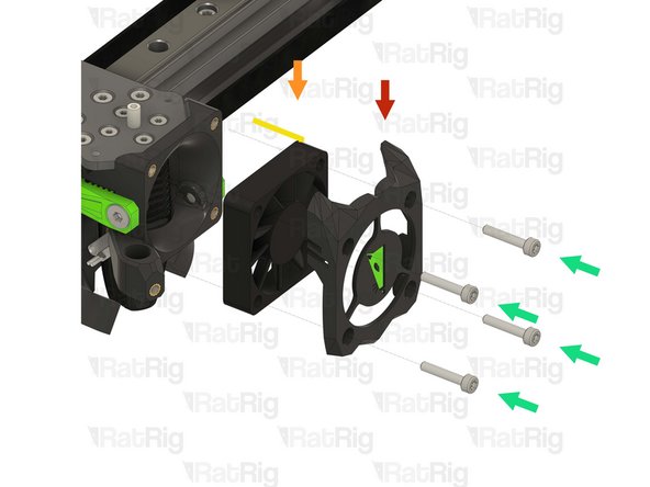
Toolhead back and duct sub-assembly from the previous step
-
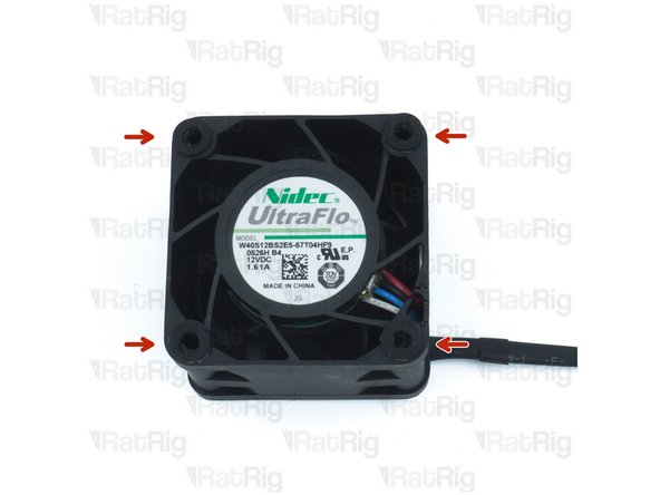
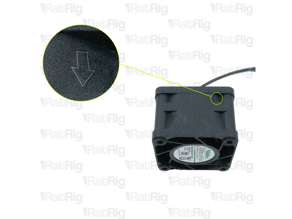
4028 part cooling fan
-
Pay special attention to the fan airflow, it should blow the air towards the cooling duct. Most fans have a small arrow indicating the airflow
-
Make sure the fan wires exit on the indicated side
-
2x M3x35 Countersink Screw
-
Install the M3x35 screws through the toolhead plate, through the 4028 part cooling fan, and tighten them into the toolhead sub-assembly
-
Do not overtighten the M3x35 Countersink Screws as you can damage the printed parts
-
Avoid using a ball-end hex key, as they are more prone to damaging, or stripping, the M3 Countersink Screw heads
-
-
-
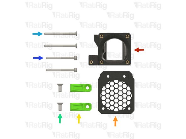
1x Prepared rr_vc4_toolhead_front from step 152
-
1x rr_vc4_toolhead_fan_grille printed part
-
2x rr_vc4_toolhead_front_clamp printed part
-
2x M4x10 Countersink Screw
-
2x M3x40 Countersink Screw
-
2x M3x35 Cap Head Screw
-
-
-
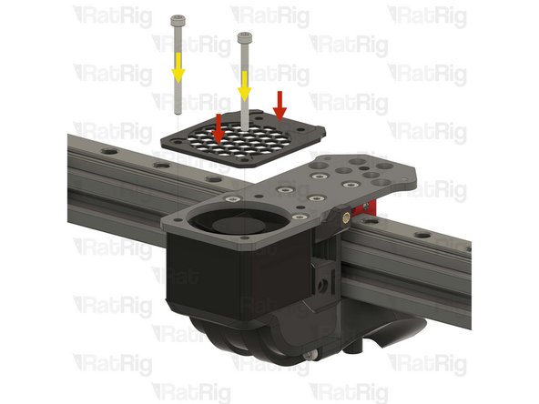
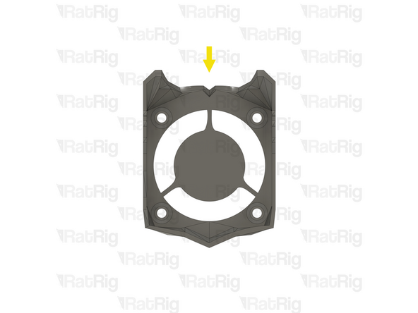
rr_vc4_toolhead_fan_grille printed part
-
Prepared rr_vc4_toolhead_front from step 152
-
2x M3x35 Cap Head Screw
-
Install the M3x35 Cap Head Screws through the fan grille (paying close attention to the orientation of the printed part), the toolhead plate, the 4028 part cooling fan, and tightening them into the toolhead sub-assembly
-
2x M3x40 Countersink Screw
-
Install the M3x40 Countersink screws though the toolhead plate and the toolhead front, but do not tighten them yet
-
Do not overtighten any of the screws as you can damage the printed parts
-
Avoid using a ball-end hex key, as they are more prone to damaging, or stripping, the M3 Countersink Screw heads
-
-
-
Lift the M3x40 Countersink Screw almost all the way out of the toolhead
-
Form a small loop on the belt as shown
-
Insert the belt loop into the marked slot
-
Reinsert the M3x40 Countersink Screw, making sure the belt goes around it, as shown in the picture, then tighten the screw fully
-
Pull the opposite end of the CoreXY belt you are installing, slowly, until the end fits flush in the cut out on the toolhead
-
-
-
rr_vc4_toolhead_front_clamp printed part
-
Hook the belt clamp onto the exposed screw, then rotate it into position, making sure it levers against the screw
-
When correctly installed, the belt clamp should sit flush with the toolhead front
-
-
-
1x M4x10 Countersink Screw
-
Install the M4x10 screw through the belt clamp and into the toolhead front, making sure the teeth of the belt clamp mesh with the belt
-
Make sure the notch on the belt clamp remains fully seated on the exposed screw section
-
Tighten the M4x10 screw to secure the belt clamp, and belt, in place
-
Pull on the belt to make sure it's secured properly, if it comes loose, try again
-
Repeat the previous two steps, and this step to secure the lower CoreXY belt to the toolhead
-
-
-
Feed the lower CoreXY belt through the marked slot on the back part of the toolhead
-
Prepared rr_vc4_toolhead_back_clamp from step 155
-
Pull the belt end gently to remove any slack and then insert the belt clamp into the back of the toolhead, pushing it in fully
-
Do not cut off any excess belt at this point
-
-
-
M3x35 Cap Head Screw
-
Insert the M3x35 Cap Head Screw, tightening it into the rr_vc4_toolhead_back_clamp whilst gently pulling on the end of the belt on the opposite side
-
-
-
Repeat the previous two steps to attach the upper CoreXY belt to the toolhead
-
Cut the excess off of both the upper and lower belts
-
It is recommended to leave 2-3mm of excess belt to make future maintenance easier
-
Please note: The hybrid belts will be installed during the commissioning guide
-
-
-
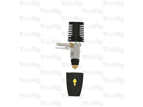
Phaetus Rapido Hotend from step 43
-
The V-Core 3.2H toolhead requires the UHF adapter and silicone sock to be installed on the Rapido hotend. If not already installed on the hotend, make sure to install them. These parts were provided in the original box the Rapido came in
-
4x M2.5x6 Countersink Screw
-
PTFE tube from step 43
-
Cut the PTFE tube to a length of 24.5mm, discard the excess to avoid confusion
-
If you are installing a brand new Rapido hotend:
-
Remove the two countersink screws on top of the Rapido
-
Remove the V6-style adapter, it is not required for the Rat Rig toolhead
-
-
-
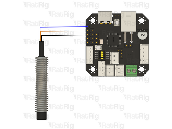
Please note: The wire colours shown in the image are for illustration purposes only
-
Hotend Heater - Shown in red: Cut the wires to a length of 150mm and strip 5-10mm off the end, to expose the inside conductor
-
Thermistor - Shown in blue: Cut the wires to a length of 160mm and crimp a JST 2 connector to them
-
The thermistor is a resistor that varies with temperature. The wire order does not matter when attaching the JST connector as a resistor does not have a polarity
-
-
-
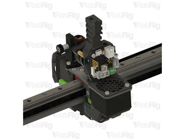
Phaetus Rapido hotend in UHF configuration
-
Insert the Rapido hotend into the toolhead from the underside, making sure to route the cables through the slot on the left side of the toolhead
-
Look through the four marked holes, checking if the holes in the Rapido heatsink align with them
-
If all four holes are aligned correctly, skip to step 176
-
If the holes do not align, follow the next steps to rotate the Rapido hotend heatsink
-
-
-
Please note: The images provided show the Phaetus Rapido V2, but the process is the same for the V1
-
Gently push down on the silicone sock to remove it
-
Loosen, but do not remove, the set screw in the heatsink
-
-
-
Please note: The images provided show the Phaetus Rapido V2, but the process is the same for the V1
-
Remove the three 2.5mm Cap Head Screws from the hotend
-
Carefully rotate the heatsink until the three screw holes align again
-
There is no way to tell how much the heatsink needs to be rotated for the wiring to align on the toolhead, it might need a 120º turn, or it might need a 240º turn. It is a matter of trial and error
-
-
-
Please note: The images provided show the Phaetus Rapido V2, but the process is the same for the V1
-
Insert the three 2.5mm Cap Head Screws back in and gently tighten them
-
DO NOT overtighten the screws. They are only 2.5mm and will break, or strip, if excessive force is applied
-
Gently fasten the set screw in the heatsink
-
DO NOT overtighten the set screw. If excessive force is applied, the heatbreak will be permanently damaged
-
Reinstall the silicone sock
-
Attempt to install the hotend into the toolhead, as shown in step 172
-
If the cables now align correctly, proceed with step 176. If the cables still do not align, return to step 173
-
-
-
4x M2.5x6 Countersink Screw
-
Tighten the M2.5x6 Countersink Screws to secure the hotend to the toolhead
-
Avoid using a ball-end hex key, as they are more prone to damaging, or stripping, the M2.5 Countersink Screw heads
-
PTFE tube - 24.5mm
-
Insert the PTFE tube in to the marked hole, push it downwards until it stops
-
-
-
Rat Rig Endstop
-
2x M3x6 Cap Head Screw
-
Insert the M3x6 Cap Head Screws through the endstop and secure them into the toolhead
-
Do not overtighten the M3x6 Cap Head Screws as you can damage the endstop or printed parts
-
-
-
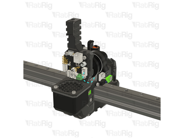
1x rr_toolhead_vc3_shourd printed part
-
1x 4010 hotend fan from step 42
-
4x M3x16 Cap Head Screw
-
-
-
rr_toolhead_vc3_shourd printed part
-
Clean the sacrificial layers on the rr_toolhead_vc3_shourd printed part, obtaining a clean passthrough hole
-
It is recommended to remove the sacrificial layers by using a correctly sized drill, screwdriver, or hex key
-
Prepared rr_toolhead_vc3_shourd printed part
-
-
-
Prepared rr_toolhead_vc3_shourd printed part
-
4010 hotend fan from step 42
-
Route the 4010 hotend fan wires as shown
-
Pay special attention to the fan airflow, it should blow the air towards the hotend heat sink. Most fans have a small arrow indicating the airflow. If not, the fan label should be facing the hotend
-
4x M3x16 Cap Head Screw
-
Insert the M3x16 Cap Head Screws through the toolhead shroud printed part, through the 40mm fan, and fasten them into the Rat Rig toolhead front
-
Do not overtighten the M3x16 Cap Head Screws as you can damage the printed parts
-
-
-
1x LDO Orbiter v2 / v2.5 Extruder
-
Please note: The LDO Orbiter extruder is not included in the kit and must be sourced separately
-
2x M3x8 Cap Head Screw
-
-
-
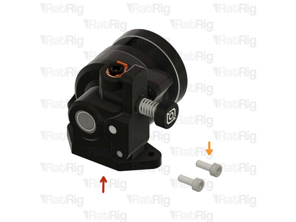
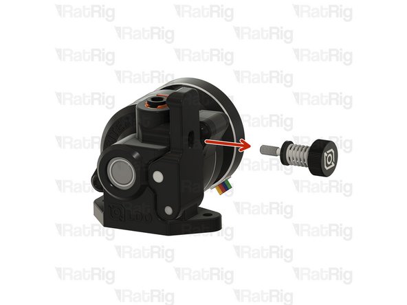
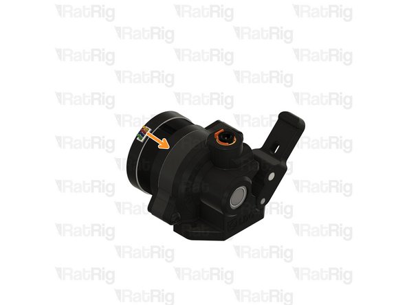
Loosen and remove the tensioning screw from the Orbiter extruder
-
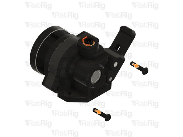
Remove the two marked front screws
-
Carefully detach the Orbiter extruder stepper motor from the housing
-
-
-
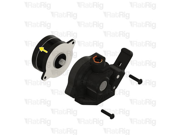
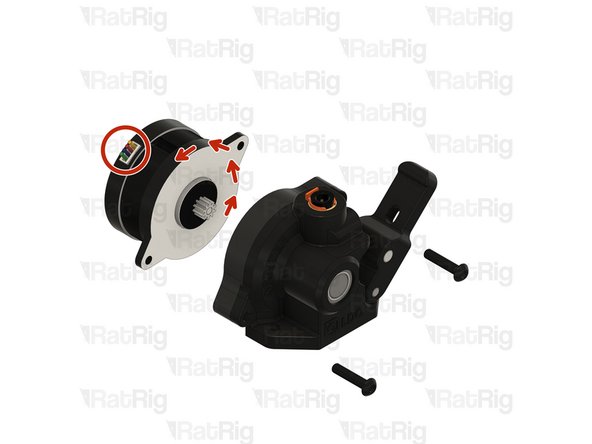
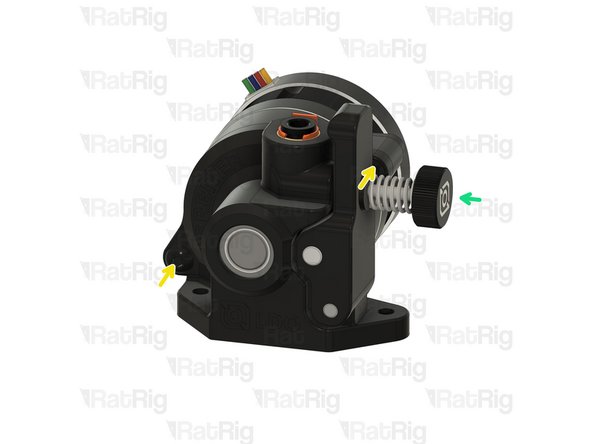
Rotate the stepper motor 180º until the wires come out from the top
-
Carefully reinstall the stepper into the Orbiter extruder housing
-
Reinstall the front screws
-
Reinstall the tensioning screw
-
-
-
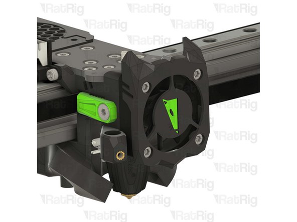
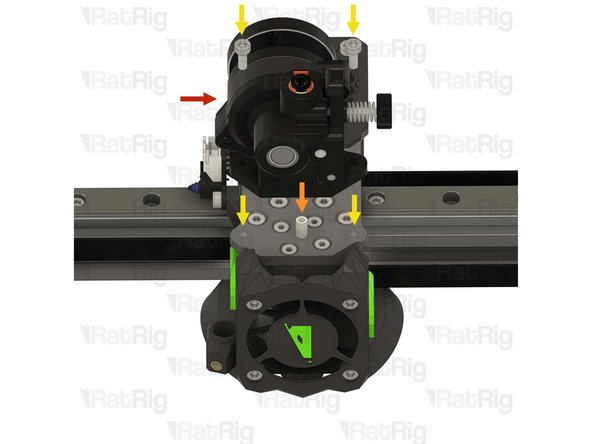
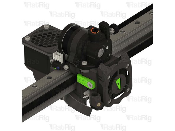
Prepared Orbiter extruder from the previous step
-
Align the Orbiter extruder with the PTFE tube
-
2x M3x8 Cap Head Screw
-
Insert the M3x8 Cap Head Screws into the Orbiter extruder and fasten them to the Rat Rig toolhead plate
-
Do not overtighten the M3x8 Cap Head Screws as you can strip the threads in the toolhead plate
-
-
-
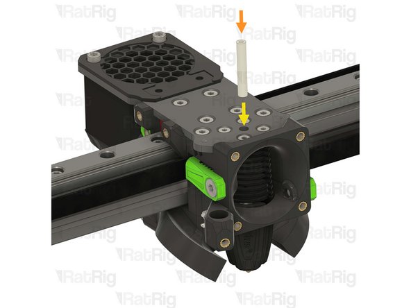
1x Rat Rig SuperPinda Probe by P&F
-
Please note: Unless you previously used the SuperPinda Z-probe one on the V-Core 3.1, it must be sourced separately as it is not included in the kit
-
If you did previously use the SuperPinda Z-probe, it was removed from the EVA toolhead in step 41
-
1x M3x5 Set Screw
-
-
-
Rat Rig SuperPinda Z-Probe by P&F
-
Insert the SuperPinda into the printed part, from the top
-
M3x6 Set Screw
-
Thread the set screw into the printed part to hold the Z-probe. Do not tighten it yet
-
Adjust the position of the Z-probe, up or down, so that the Z-probe tip is 1mm higher than the hotend nozzle
-
Tighten the M3x6 Set Screw to secure the Z-probe in place
-
-
-
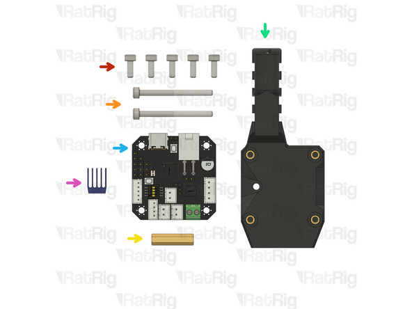
5x M3x8 Cap Head Screw
-
2x M3x35 Cap Head Screw
-
1x Threaded Brass Spacer M3 x 20mm
-
1x rr_vc4_toolhead_toolboard_vertical printed part
-
1x BIGTREETECH EBB42 Toolboard
-
Please note: The BIGTREETECH EBB42 toolboard is not included in the kit and must be sourced separately
-
1x TMC2209 driver heatsink (Included in the EBB42 toolboard box)
-
-
-
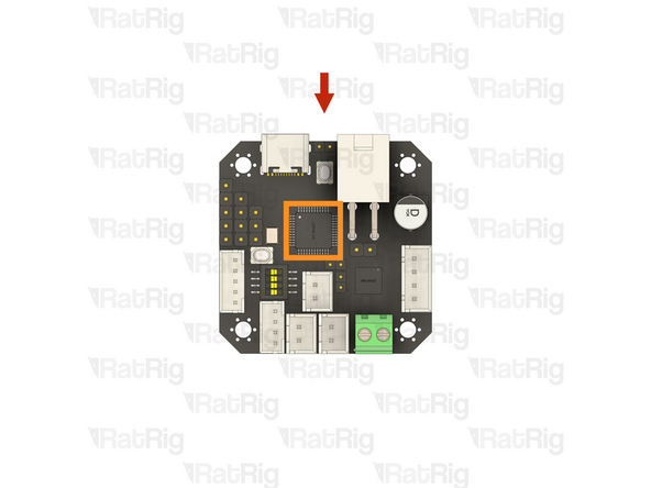
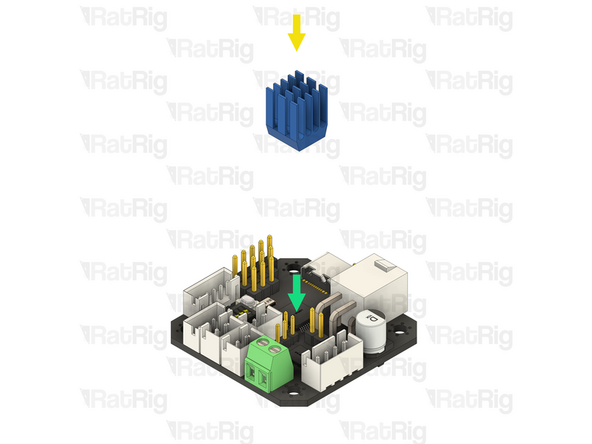
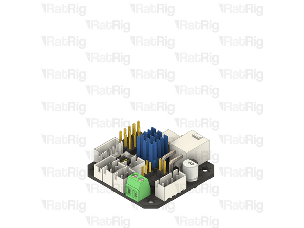
BIGTREETECH EBB42 toolboard
-
TMC2209 stepper motor driver IC
-
TMC2209 driver heatsink
-
Remove the adhesive backing from the heatsink and gently press it onto the TMC2209 stepper motor driver
-
-
-
Screw the threaded brass spacer M3x20mm onto the exposed thread of the marked Orbiter screw
-
Do not overtighten the brass spacer as it is possible to strip the threads
-
Insert the M3x35 Cap Head Screws into the rr_vc4_toolhead_toolboard_vertical printed part and fasten it onto the toolhead as sown
-
Do not overtighten the M3x35 Cap Head Screws as you can damage the printed parts
-
1x M3x8 Cap Head Screw
-
Insert the M3x8 Cap Head Screw through the printed part and into the threads of the brass spacer. Tighten the screw to secure the toolboard mount to the brass spacer
-
-
-
Prepared BIGTREETECH EBB42 toolboard from step 189
-
4x M3x8 Cap Head Screw
-
Insert the M3x8 screws through the toolboard and thread them into the toolboard mount printed part
-
Do not overtighten the M3x8 Cap Head Screws as you can damage the toolboard or the printed part
-
-
-
The next steps will detail both wiring the toolhead components to the toolboard, as well as connecting all of the stepper motors to the Octopus motherboard
-
-
-
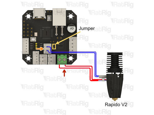
Please note: The wire colours shown in the image are for illustration purposes only
-
Hotend Heater - Shown in red
-
Loosen the two screws in the terminal, insert the one wire in to each, and then tighten the screws to secure the wires
-
After tightening the screws, gently pull the cable to make sure it is firmly connected. If the cable releases or moves when pulling, reinsert it and tighten the screw
-
Thermistor - Shown in blue
-
The thermistor wires are very fragile, bending them at a sharp angle can damage the conductors within, leading to a thermistor failure
-
The marked jumper only needs to be installed if the Rapido is using a PT1000 thermistor (These the Rapido plus models)
-
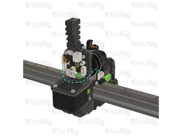
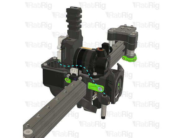
Route the hotend wires as shown
-
-
-
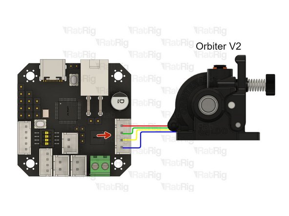
Connect the Orbiter extruder stepper motor cable to the marked connector on the toolboard
-
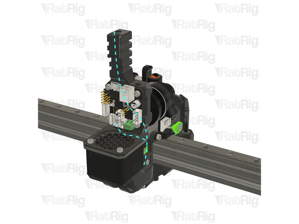
Route the wires as shown
-
-
-
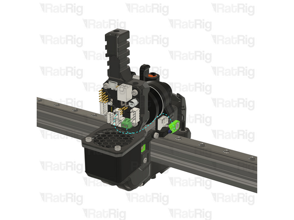
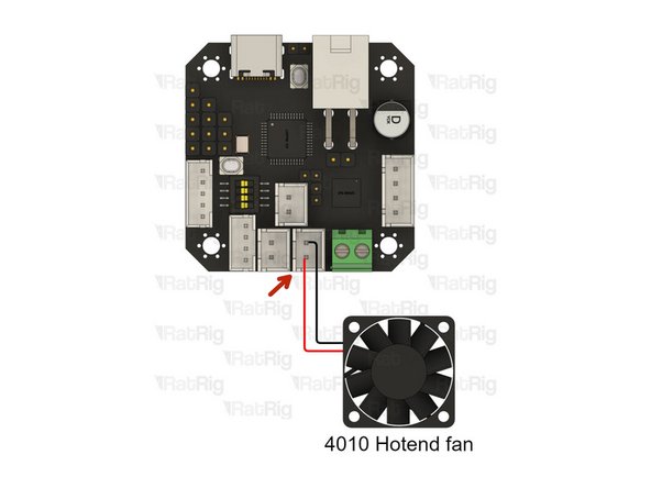
4010 hotend fan - 24V
-
Connect the 4010 hotend fan to the marked connector, making sure the positive and negative wires are in the correct positions
-
Route the wires as shown
-
Cable ties can be used to secure the wiring to the toolhead
-
-
-
Take the X-axis endstop wiring from step 10 and cut one end to a length of 130mm
-
Strip 2mm of the insulation from each wire
-
Use a crimping tool to install a Micro JST crimp onto each wire
-
These crimps, and the 5 position connector housing are found inside the EBB42 toolboard box
-
Refer to the provided image to correctly wire the cable
-
Wiring the endstop incorrectly will lead do damage of the endstop, or the toolboard. Double check the connections before proceeding
-
-
-
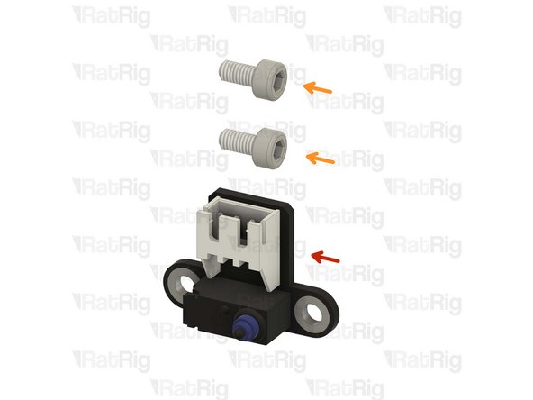
Rat Rig Endstop
-
Prepared X-axis endstop cable
-
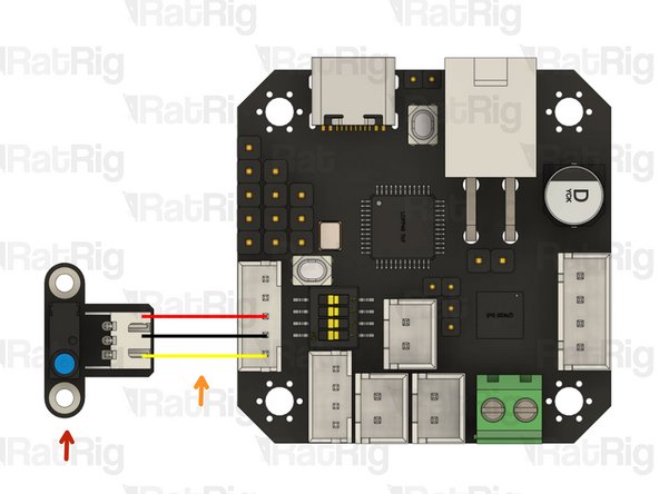
Connect the smaller Micro JST connector to marked connector on the toolboard, and the larger JST-XH connector to the endstop
-
Route the wires as shown
-
-
-
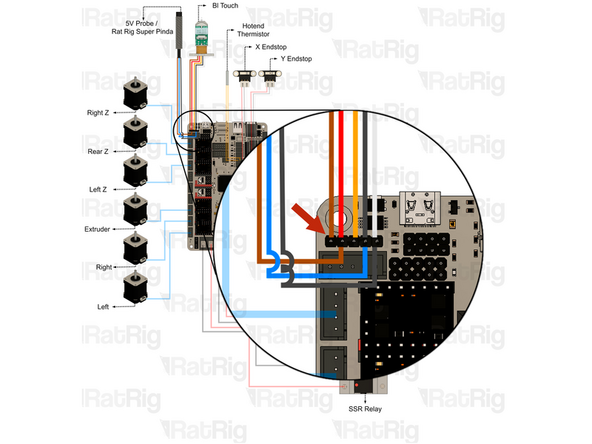
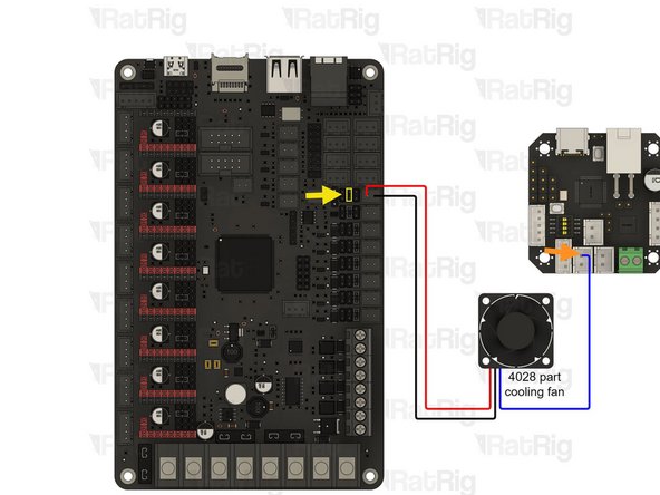
4028 Part cooling fan
-
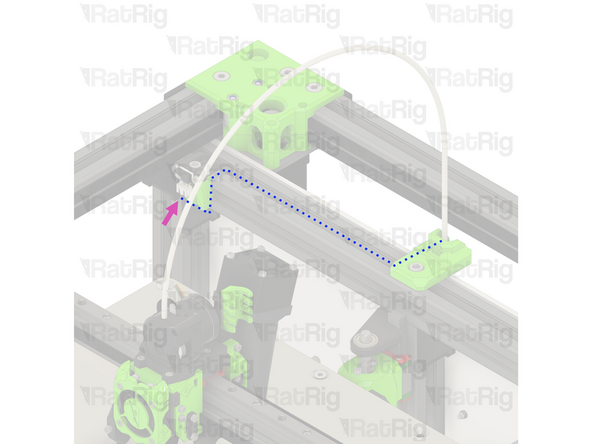
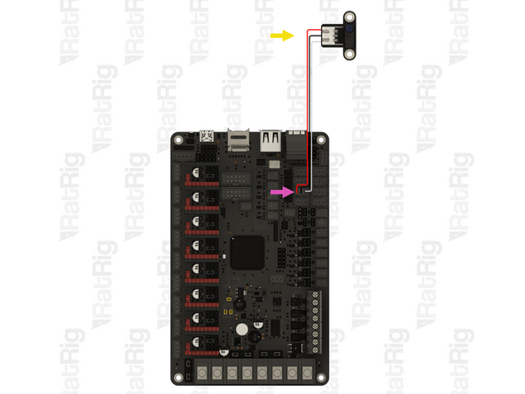
Connect the PWM wire to the negative pin (the one closest to the middle of the toolboard) of the marked connector
-
It may be desirable to shorten the PWM wire now that it is connecting to the toolboard, rather than being routed back to the Octopus
-
Connect the positive and negative wire back to the marked connector on the Octopus motherboard
-
Route the PWM wire as shown
-
-
-
Connect the Z-probe wires to the marked connector on the toolboard
-
Route the wires as shown
-
-
-
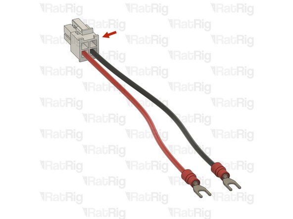
The 4 pin power connector, and crimps, are provided in the EBB42 toolboard box
-
Please note: The DC wires and fork terminals are not included in the kit and must be sourced separately
-
It is recommended to use 18 AWG wiring, and 3.7mm fork terminals
-
The exact length of wiring needed will vary based upon machine size
-
Carefully check the wire positions, if the polarity is incorrect, it will destroy the electronics
It would be helpful to know what kind of stranding, and possibly what kind of insulation as well, to use for the wires, given that these wires are part of the umbilical and need to have at least some measure of flexibility.
I've noticed, for example, that 18 AWG PVC wire with 16/30 stranding is a little stiff, and certainly not at a "wet noodle" level of flexibility.
-
-
-
Cable - USB-A to USB-C Cable 1500mm (route as shown, along the PTFE tube)
-
Please note: An appropriate length USB cable is not included in the kit and must be sourced separately
-
Connect the USB-C end to the toolboard
-
Connect the USB-A end to an available USB port on the Raspberry Pi
-
It is important to make sure that the USB-C connector cannot move or come loose. Use cable ties to secure it to the toolhead printed part
-
-
-
Prepared EBB42 power cable from step 200
-
Red Wire- Power Input +24V on the Toolboard and [+V] on the Power Supply
-
Black Wire- Power Input GND on the Toolboard and [-V] on the Power Supply
-
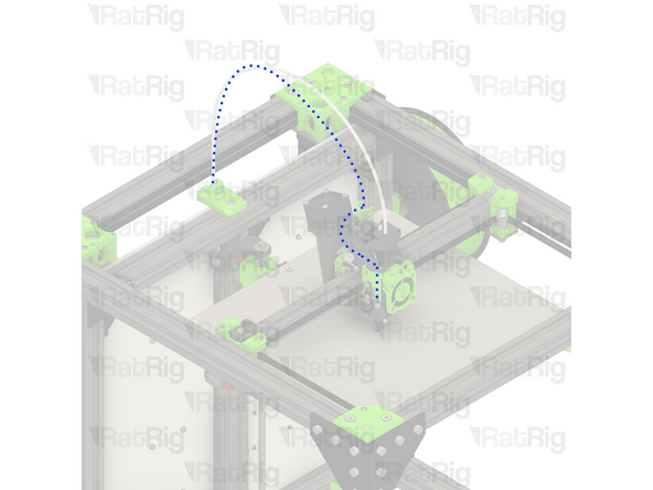
Route all of the toolhead cables back to the electronics on the machine. The wiring can be cable tied together to keep it neat
-
-
-
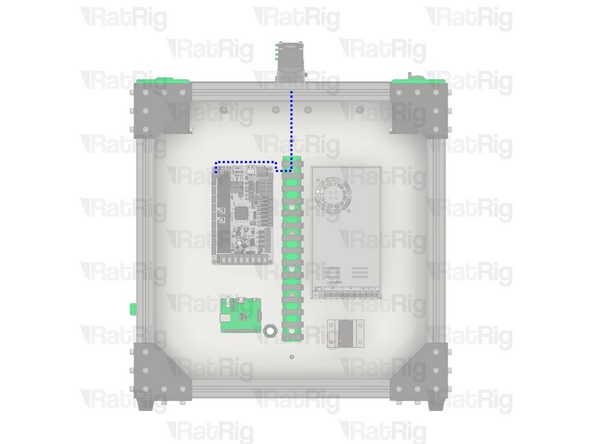
Rat Rig Endstop - Y-axis
-
Cable 2000mm - 3 Conductor 24AWG - JST XH2.54 to JST XH2.54 (Endstop pin out)
-
Connect one end of the endstop cable to the Y-axis endstop
-
Route the cable back to the electronics as shown. The 3030 extrusion slot can be used to keep it neat
-
Connect the other end to the Octopus motherboard
-
Please note: Double check the connections, incorrect endstop wiring can damage the Octopus motherboard
-
-
-
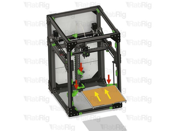
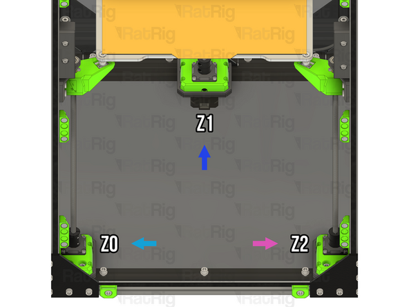
Rotate the lead screws by hand, to lower the Z arms 10-20mm, enough for the bed assembly to be installed without hitting the gantry or toolhead
-
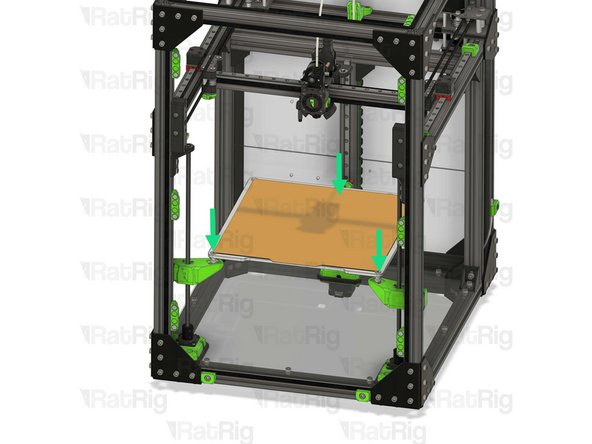
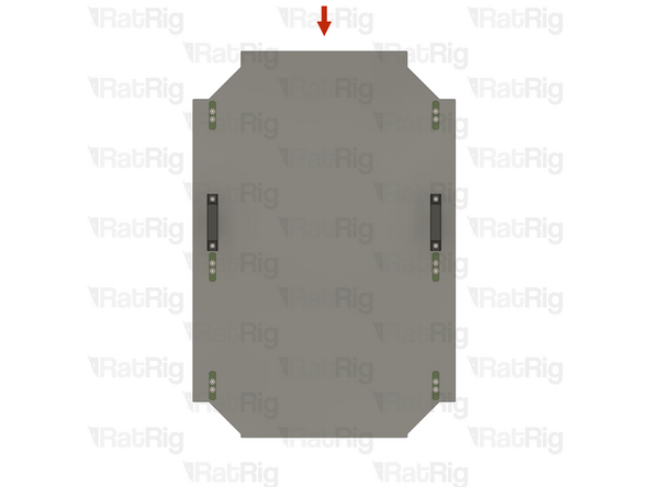
Retrieve the bed assembly which was removed in step 19
-
Insert the bed assembly into the V-Core assembly
-
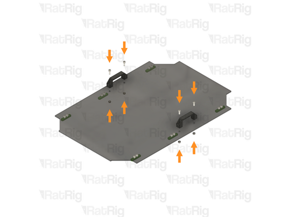
Set the bed assembly back onto the Z-axis arms
-
Secure the bed wires to the back Z-axis arm using cable ties
-
Feed the bed wiring through the rear panel
-
Reconnect the heated bed thermistor to the Octopus motherboard, and the AC connections to the SSR and PSU, using the notes or photo taken in step 19
-
-
-
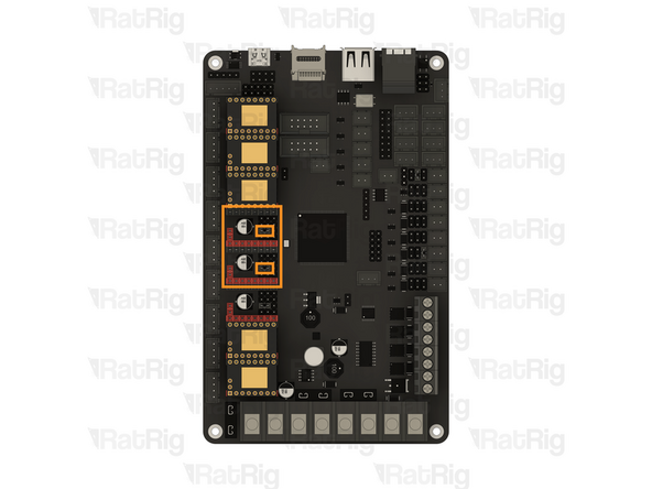
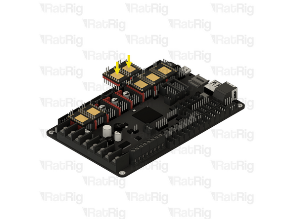
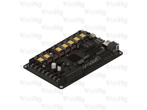
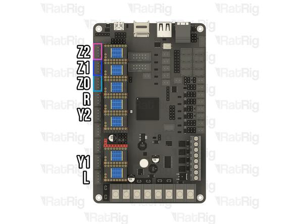
Octopus motherboard
-
Verify that the jumpers for the two marked stepper drivers are set correctly, as shown in the image
-
BIGTREETECH TMC2209 Driver
-
Install a TMC2209 stepper motor driver into each marked socket on the Octopus motherboard
-
-
-
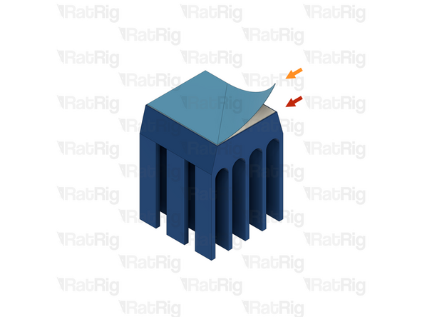
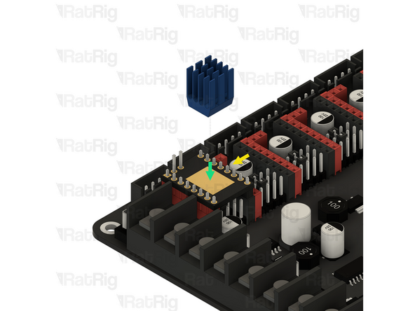
1x Blue anodised heatsink
-
Adhesive pad cover
-
The adhesive to secure the heatsink to the stepper driver has a thin, blue, plastic cover, this needs to be peeled off
-
1x BIGTREETECH TMC2209 stepper driver
-
Align the heatsink with the centre of the stepper driver as shown
-
Press the heatsink down gently for 5-10 seconds to make sure it adheres well
-
Make sure all seven stepper motor drivers have heatsinks installed
-
-
-
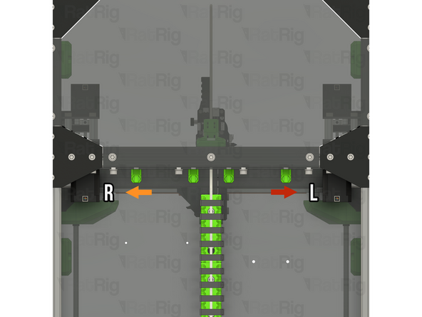
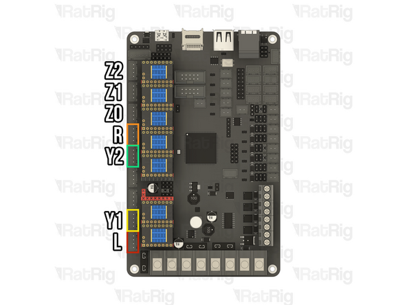
Identify and connect the stepper motors to the Octopus motherboard as shown
-
The left CoreXY stepper motor is on the right when looking at the V-Core 3.2H from behind
-
The right CoreXY stepper motor is on the left when looking at the V-Core 3.2H from behind
-
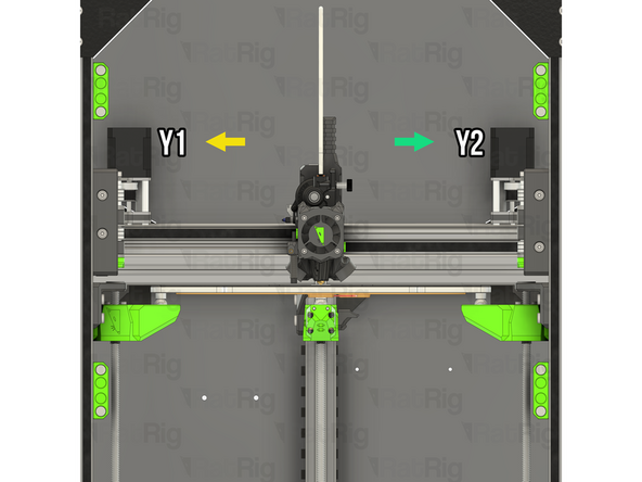
The Y1 stepper motor is on the top left when looking at the V-Core 3.2H from the front
-
The Y2 stepper motor is on the top right when looking at the V-Core 3.2H from the front
-
-
-
Identify and verify that the Z-axis the stepper motors are connected to the correct ports on the Octopus motherboard as shown
-
The Z0 stepper motor is on the front left when looking at the V-Core 3.2H from the front
-
The Z1 stepper motor is on the rear middle when looking at the V-Core 3.2H from the front
-
The Z2 stepper motor is on the front right when looking at the V-Core 3.2H from the front
-
-
-
Although every effort was made to prevent changes to any enclosure panels, the front door panel requires modification as the existing handle positions interfere with the tensioner assemblies
-
If your V-Core 3.2H does not have enclosure panels, you can skip to the end of the guide
-
Retrieve the door panel assembly which was removed in step 2
-
Loosen, and remove, the four M6x16 Cap Head Screws, and the four M6 Locking Hex Nuts, securing the handles to the panel
-
Measure 25mm horizontally from the center of the existing holes, and mark the panel using a permanent marker
-
-
-
Drill all four marked holes using a sharp 6.5mm twist drill
-
Please note: Depending on the panel material, it may be beneficial to drill a pilot hole first with a smaller drill size. Plastics like acrylic are prone to cracking and shattering
-
2x V-Slot Door Handle
-
4x M6x16 Cap Head Screw
-
4x M6 Locking Hex Nuts
-
Reinstall the two handles into the new positions using the previously removed M6x16 Cap Head Screws and M6 Locking Hex Nuts
-
-
-
Additional changes are required for a V-Core 3.2H - 200, due to moving the magnet holders in step 52
-
If you are upgrading a 300, 400 or 500 sized machine, you can skip to step 214
-
Door magnet holders
-
Loosen, and remove, the four M6x12 Cap Head Screws, and the four M6 Washers, securing the upper magnet holders to the panel
-
Set the M6x12 Cap Head Screws, M6 Washers, and magnets holders aside, they will be reinstalled in a few steps
-
-
-
V-Core 3.2H assembly
-
Install the door on to the V-Core 3.2H frame
-
Look through the panel, and using the upper frame magnet holders as a template, mark the four centre points on the door panel using a permanent marker
-
-
-
Drill all four previously marked holes using a sharp 6.5mm twist drill
-
Please note: Depending on the panel material, it may be beneficial to drill a pilot hole first with a smaller drill size. Plastics like acrylic are prone to cracking and shattering
-
4x M6x12 Cap Head Screw & M6 Washer
-
2x Door Magnet Holder
-
Reinstall the two door magnet holders into the new positions using the previously removed M6x12 Cap Head Screws and M6 Washers
-
-
-
Retrieve the enclosure panels which were removed in steps 2, 3 & 4
-
Align the side panels to the frame as shown
-
Secure the panel in place by fastening the all of the M6x12 Cap Head Screws
-
Reattach the spool holder
-
Rest the door panel on the horizontal 3030 panel mounts, then rotate towards the printer to secure it
-
Place the top panel onto the top of the printer
-
-
-
Find the belt package labelled HW4226GC - Timing Belt - GATES - 2GT 9mm (3.2 meters pack) from the pack labelled HW4137MK - Rat Rig V-Core 3.2H - Hardware Pack B - Mechanical
-
Unroll the belt and cut two lengths based upon which size V-Core 3.2H you are assembling:
-
V-Core 3.2H 200x200: 2x 970 mm
-
V-Core 3.2H 300x300: 2x 1170 mm
-
V-Core 3.2H 400x400: 2x 1370 mm
-
V-Core 3.2H 500x500: 2x 1570 mm
-
Set these belts aside until they are required during the commissioning guide
-
Please note: During the commissioning guide, do not cut these belts any shorter. The V-Core 3.2H requires longer Hybrid belt lengths than the V-Core 4
-
-
-
Next step: Now that the assembly is finished, it is time to follow the V-Core 3.2H commissioning guide
-