
-
-
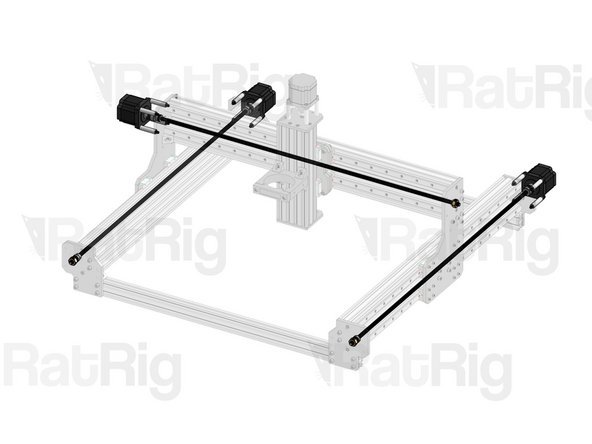
Lay the Y Axis C-Beam profiles on top of the X-Base 2040 profiles. You're about to mount the XZ Axis on the XY Carriages. Either ask for a friend's help or get a couple of boxes as temporary support for your XZ Axis.
-
X Base 2040 profiles (they are 5mm shorter than your X Axis)
-
XY Carriages
-
XZ Axis
-
-
-
Cap Head Screw M5x12mm
-
Washer M5 Black
-
Cap Head Screw M5x16mm
-
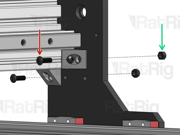
Repeat step on the opposite XY carriage
-
-
-
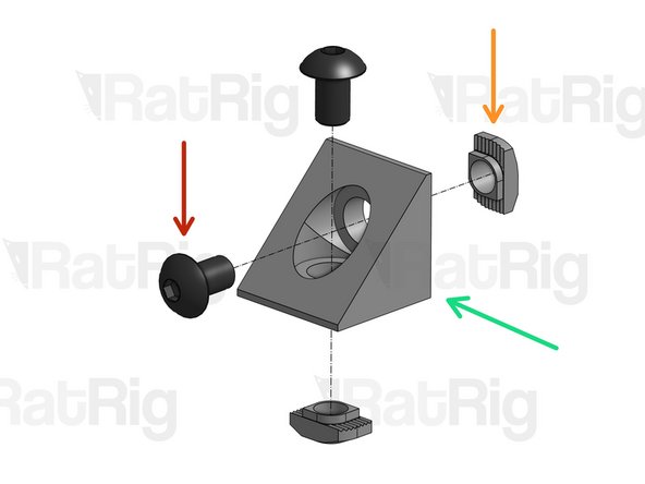
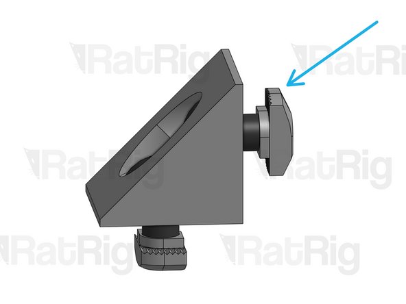
Button Head Screw M5x16mm
-
Hex Locking Nut M5
-
Repeat step on the Angle Corners on the opposite XY carriage.
From my earlier comment, it will make it easier to loosen the previously tightened button head screws as you can’t get the second screw into the other hole in the Angle Corner.
Peter Newman - Resolved on Release Reply
-
-
-
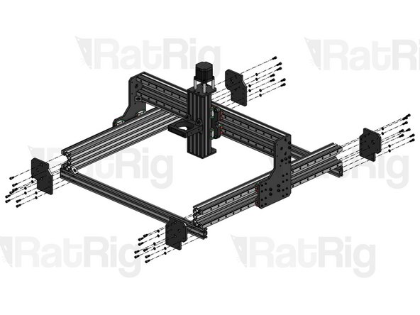
Set the 4 Y Plates in position, aligning them so they are flush with the ends of the 2040 profiles, but don't give the final tightening just yet.
-
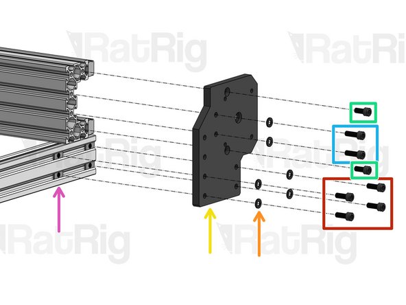
Flat T-Nut M5. Slide it inside the slot through the opening at the end.
-
These are different from the Drop-in T-Nuts you've used until now.
-
Y Plate
-
Washer M5 Black
-
Cap Head Screw M5x12mm
-
Cap Head Screw M5x16mm
-
Cap Head Screw M5x14mm
-
-
-
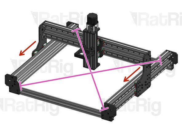
We can't overstate how important this step is. Take your time to get it right or your machine's performance and lifespan will be affected.
-
Measure the diagonals of the square formed by the machine's frame. They need to be exactly the same length.
-
To make a precise measurement, get 2 pointy sticks. Each stick needs to have more than half of the diagonal length. Position each stick on opposite corners of the diagonal. They will meet in the middle, overlapping each other.
-
Mark the position where they overlap, remove the sticks from the frame, and measure their combined length.
-
Move the XZ Gantry back and forth across the entire range of movement, so the Y plates settle in the right positions.
-
Move the gantry all the way to the front and give the final tightening on the front Y plates.
-
Move the gantry all the way to the back and give the final tightening on the back Y plates.
-
-
-
Repeat step for 4 Angle Corners
-
Button Head Screw M5x8mm
-
Angle Corner
-
Drop-in T-Nut M5
-
Do not tighten the T-Nuts. Screw them in just enough so they don't fall.
-
-
-
Repeat this step on each of the 4 corners of the frame.
-
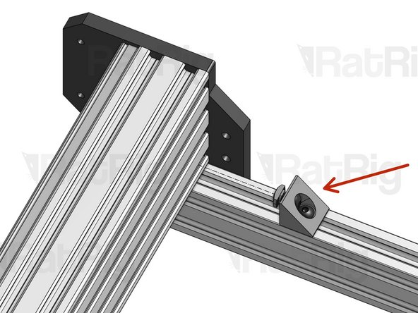
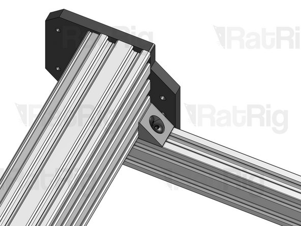
Fit the Angle Corners you set up on the last step inside the profile slots and tighten them.
-


Cancel: I did not complete this guide.
5 other people completed this guide.

One Comment
Managed to do the first part alone…. it’s really easyer to dot it with help ! We were 3 : 2 holding the X axes, on screwing all :)
Flamand Laurent - Resolved on Release Reply
This is definitely a two person job, even with some method of supporting the gantries. The reason for this is that the Y rails are out of balance, so won’t sit on their base without falling over outwards, and the same goes for the X axis which falls forward because of the weight of the mount. Trying to align the screws through the Y rail end plates into the X rail while holding them all together is a trick for even the most flexible contortionist - and these items are not light! I found it easier to secure the first Y gantry by lifting one end of the X gantry (making sure the Z gantry doesn’t fall off the lower end!) to meet the Y gantry, inserting the screws most of the way in, and then repeat for the other Y gantry, at which time the X gantry will be horizontal.
Peter Newman - Resolved on Release Reply
I did it alone with the help of a rolled up sports mat that I used as a support. To prevent the gantry from falling off the lower end, I tied it with the cellophane that was around the bearing. That way you can safely remove the red plastics.
Amaury SIX -