Reputation over time
It looks like this user hasn't gained any reputation yet.
Once they have, you'll be able to view a graph of their reputation gained over time.
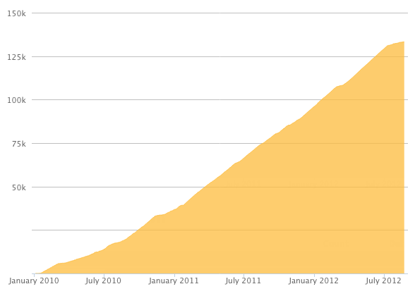
Here's a preview of what the graph will look like:
Reputation Breakdown
No reputation gained yet.
225
@ratrig Erm, have I missed the part explaining how to install the Z Limit Switch, please?
Actually, I’m not sure if these Angle Corners are of any real use, especially the forward facing ones. They get in the way of the horizontal movement of the Z axis on the X C-Beam.
The BOM doesn’t include the 2x Cap Head Screw M5x60mm for this section and are missing from the kit.
Why would you use cap head screws when the recesses in the drag chain are countersunk. Wouldn’t countersunk screws be better? This is the same for both drag chains
Mine too! What a shame.
These instructions are fairly straightforward for the X axis, but not very helpful when installing the Y axes, especially as there’s no indication of how to keep the Y axes in ‘synchronisation"‘.
I’m also a bit surprised the flexible couplings don’t have a corresponding chamfer on the stepper motor end, as this would make thing so much easier to line up and you’d only need a grub screw and no clamp. Another suggestion would be to provide more precise measurements, or even a 3d printed, removable spacer to ensure the gap between the stepper motor and that end of the flexible coupling to ensure they’re the same for all the stepper motors.
Also (sorry) the lock collars should be replaced with a clamp, because tightening the grub screw, if it’s located anywhere other that perfectly, will just move the collar along the lead screw, obviating the effectiveness of the thrust bearing.
From my earlier comment, it will make it easier to loosen the previously tightened button head screws as you can’t get the second screw into the other hole in the Angle Corner.
This is definitely a two person job, even with some method of supporting the gantries. The reason for this is that the Y rails are out of balance, so won’t sit on their base without falling over outwards, and the same goes for the X axis which falls forward because of the weight of the mount. Trying to align the screws through the Y rail end plates into the X rail while holding them all together is a trick for even the most flexible contortionist - and these items are not light! I found it easier to secure the first Y gantry by lifting one end of the X gantry (making sure the Z gantry doesn’t fall off the lower end!) to meet the Y gantry, inserting the screws most of the way in, and then repeat for the other Y gantry, at which time the X gantry will be horizontal.
Tightening the button head screws at this point is fine, but you’ll need to loosen them later. The reason for this is that you can’t get the second screw into the other hole of the Angle Corners at Step 3 of the Y Axis installation (the next step).
If you’re saying “…don’t overtighten…”, you should provide torque wrench settings.
Page 1 of 2
Next