-
-
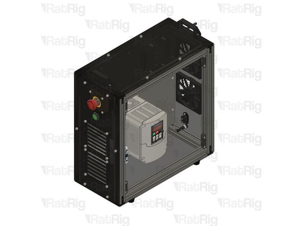
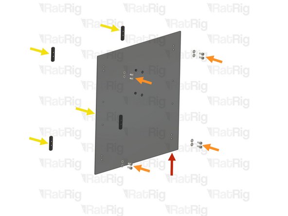
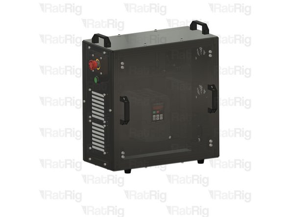
Rat Rig Universal CNC Electronics Enclosure - rear
-
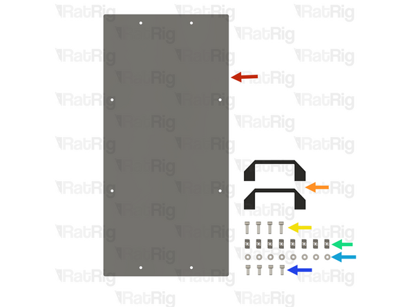
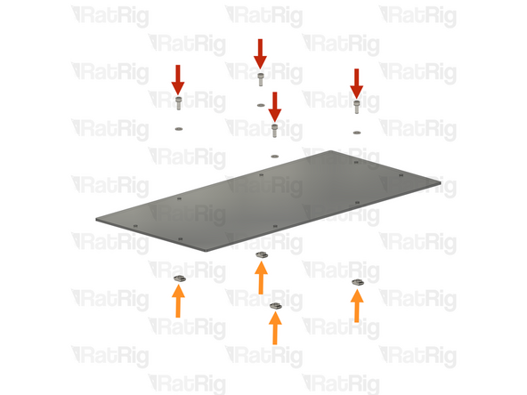
8x M5x12 Cap Head Screw
-
8x M5 Washer
-
8x 3030 Drop-in T-Nut - M5
-
3x rubber grommets
-
-
-
rubber grommets
-
Insert a M5x12 Cap Head Screw and a M5 Washer into all the holes on the panel as shown
-
Loosely tighten a 3030 Drop-in T-Nut - M5 into each screw.
-
-
-
INTERMEDIATE Prepare the following cables for the Stepper motors:
-
4x Cable - Multicore 4 Conductor - 20AWG (your desired length to reach the machine) with a Xtension Connector on one end and a JST on the other
-
Prepare only 3 in case of The Rat Rig Mill
-
3x Cable - Multicore 3 Conductor - 24AWG (your desired length to reach the machine) with a Xtension Connector on one end and a JST on the other
-
ADVANCED Prepare the following cables for the Stepper motors:
-
4x Cable - Multicore 4 Conductor - 20AWG (your desired length to reach the machine) with a Xtension Connector on one end and ferrules on the other end.
-
Prepare only 3 in case of The Rat Rig Mill
-
3x Cable (4x for the StrongHold PRO)- Multicore 3 Conductor - 24AWG (your desired length to reach the machine) with a Xtension Connector on one end and ferrules on the other end.
-
-
-
Intermediate ONLY Skip if you are assembling the advanced bundle.
-
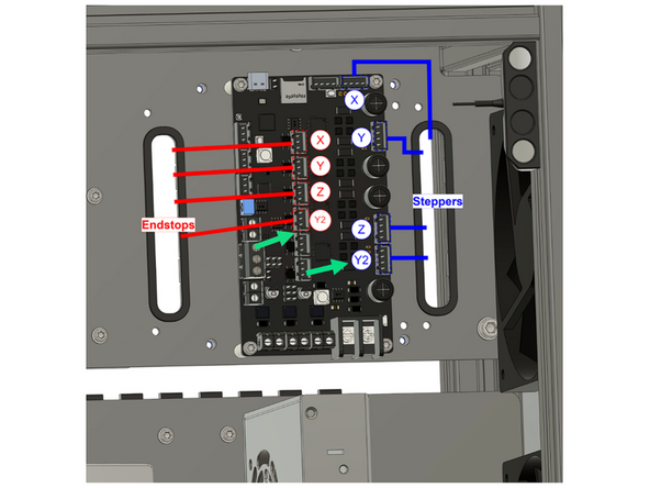
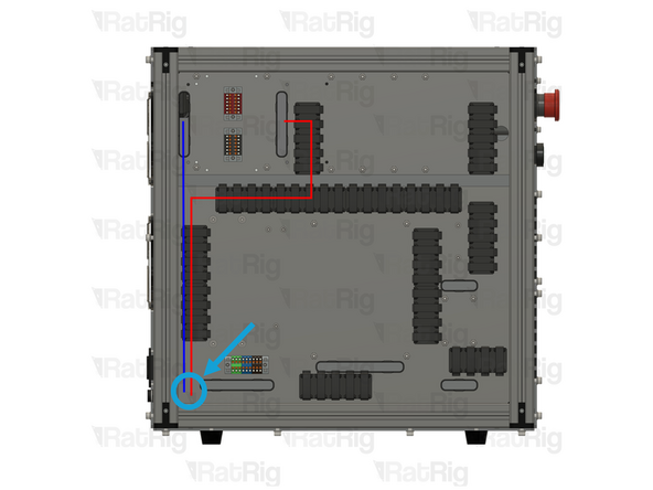
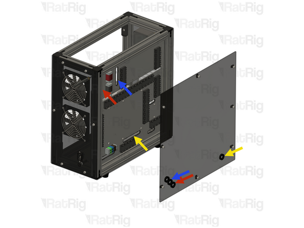
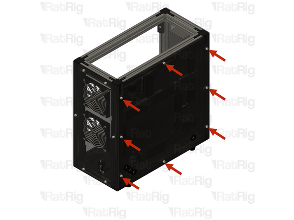
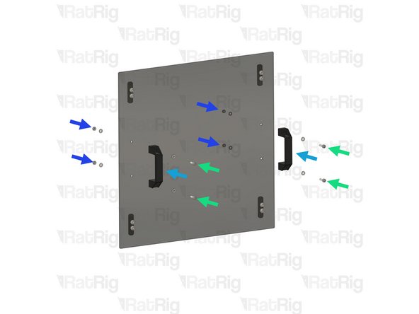
Feed all the stepper motor cables through the designated hole on the rear panel. Then insert them into the components upper panel slot, as shown.
-
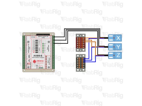
Connect them into the designated slots.
-
Feed all the endstop cables through the designated hole on the rear panel. Then insert them into the components upper panel slot, as shown.
-
Connect them into the designated slots.
-
Feed the spindle cable through the designated hole on the rear panel. Then insert them into the components lower panel slot, as shown.
-
Y2 Stepper+ endstop should only be connected if you are wiring a StrongHold Machine, it's not used in the Mill.
-
The cables should be inserted into the rear panel here.
-
-
-
Advanced ONLY
-
Feed all the stepper motor cables through the designated hole on the rear panel. Then insert them into the components upper panel slot, as shown.
-
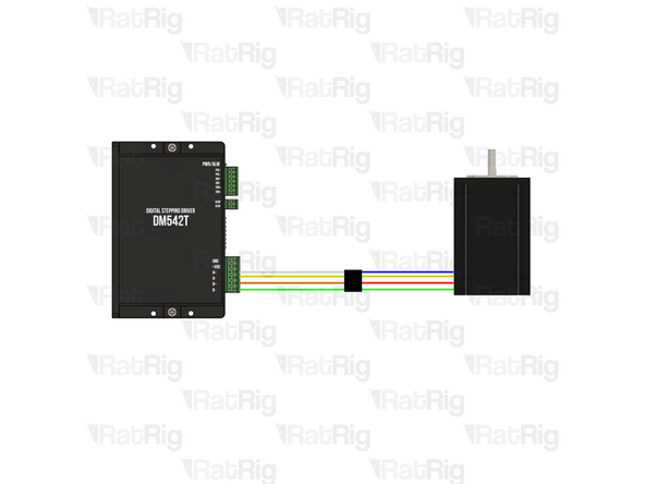
Use 20AWG 4wire cables to connect the AXBB to the steppers, as shown in the second image. Crimp ferrules onto the ends of the wires and connect them to the A+, A-, B+, and B- terminals on the drivers. Then, attach an Xtension connector to the stepper motor end. Before cutting the cable, ensure it is sufficiently long to reach the stepper motor.
-
Feed all the endstop cables through the designated hole on the rear panel. Then insert them into the components upper panel slot, as shown.
-
Use 24AWG 3wire cables to connect the AXBB to the sendstops, as shown in the third image. Crimp ferrules onto the ends of the wires and connect them to the designated terminals on the AXBB Then, attach an Xtension to the end of the wire. Before cutting the cable, ensure it is sufficiently long to reach the endstop cable.
-
Feed the spindle cable through the designated hole on the rear panel. Then insert them into the components lower panel slot, as shown.
-
Y2 stepper + endstop should only be connected if you are wiring a StrongHold Machine; it's not used in the Mill. For the Y2 Endstop, repeat the same endstop wiring scheme and connect the black wire to the I3- port.
-
-
-
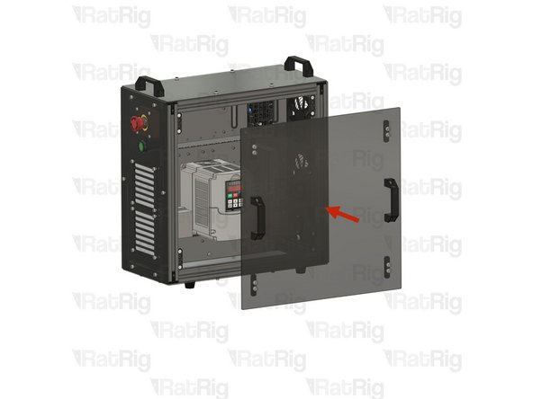
Place all T-nuts inside the T-slot extrusions an tighten the screws, securing the rear panel to the assembly.
-
-
-
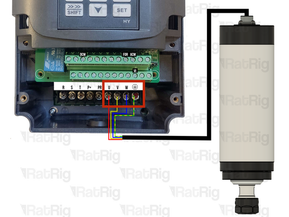
Connect the spindle cable to the VFD as shown, the wires are labed.
-
Crimp a Fork connector onto each wire before connecting it to the VFD
-
-
-
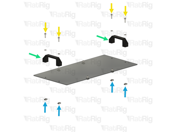
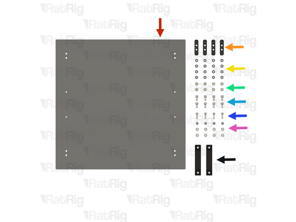
Rat Rig Universal CNC Electronics Enclosure - Single Panel - Top
-
2x V-Slot Door Handle
-
4x M5x16 Cap Head Screw
-
8x 3030 Drop-in T-Nut - M5
-
8x M5 Washer
-
4x M5x12 Cap Head Screw
-
-
-
Insert a M5x12 Cap Head Screw and a M5 Washer into all the holes on the panel as shown
-
Loosely tighten a 3030 Drop-in T-Nut - M5 into each screw.
-
Insert a M5x16 Cap Head Screw and a M5 Washer into all the V-Handle holes and thought the holes in the panel, as shown.
-
V-Slot Handle
-
Loosely tighten a 3030 Drop-in T-Nut - M5 into each screw.
-
-
-
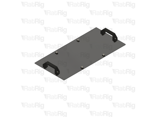
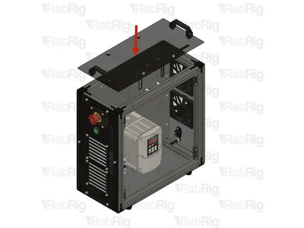
Place all T-nuts inside the T-slot extrusions an tighten the screws, securing the top panel to the assembly.
-
-
-
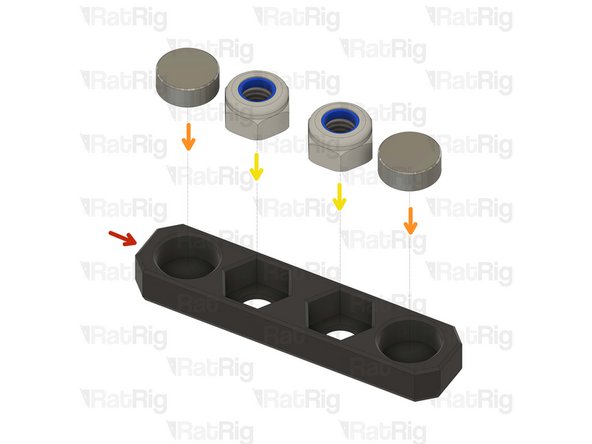
vc4_magnet_panel
-
Magnet - Neodymium disc 10x4mm
-
M6 Nylon Locking Hex Nut
-
Prepare four assemblies
-
Tip: Use a drop of super glue to prevent the magnets from coming off over time.
-
Please verify the magnet polarity in relation to the magnets on the door panel. If the polarity is inverted, the magnets will repel each other instead of attracting.
-
-
-
Rat Rig Universal CNC Electronics Enclosure - Door
-
4x Door magnet panel printed part
-
12x M6 Nylon Locking Hex Nut
-
12x M6 Washer
-
4x M5x16 Cap Head Screw
-
4x M5 Washer + 8x M5 Hex locking nut
-
V-Slot Door Handle
-
-
-
Rat Rig Universal CNC Electronics Enclosure - Door
-
(8x) M6x12 Cap Head Screw + M6 Washer
-
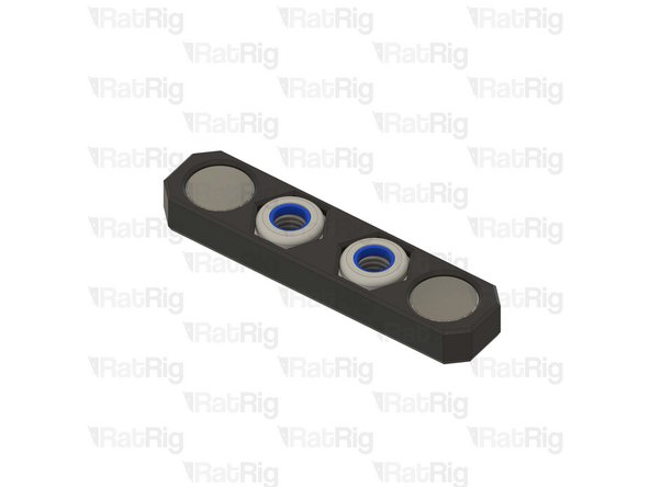
Door magnet panel assembly
-
Feed the M6x12 Cap Head screws through the M6 washers and into the door panel, then tighten them onto the hex locking nuts on the door magnet panel assembly.
-
Take care not to overtighten the M6x12 screw, as you may damage the printed parts.
-
(4x) M5x16 Cap Head Screw + M5 Washer
-
V-Slot Door Handle
-
(4x) M5 Hex locking nut + M5 washer
-