
-
-
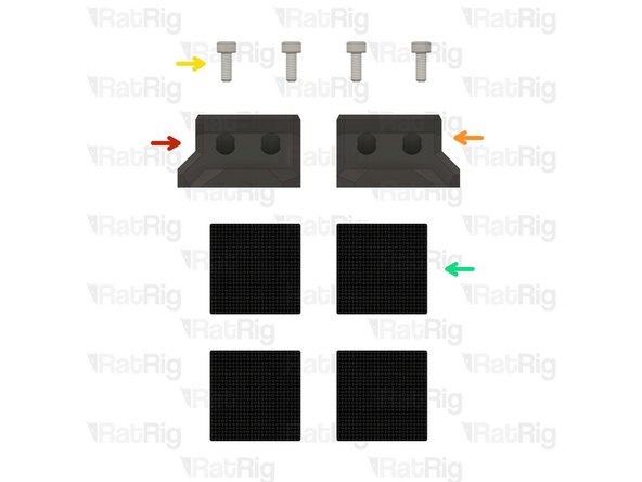
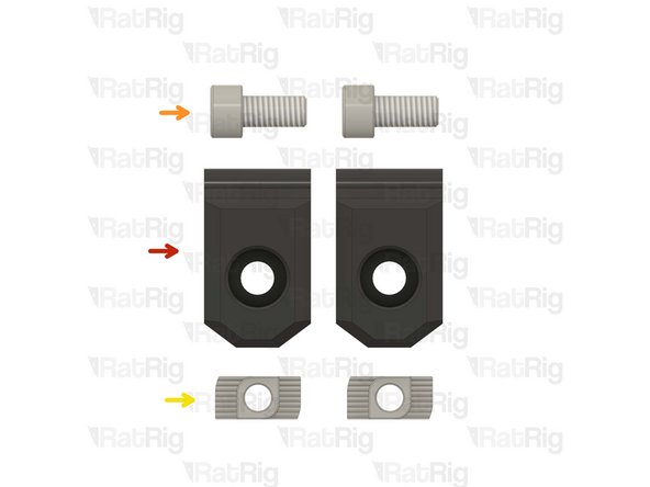
19x Heat Insert M3
-
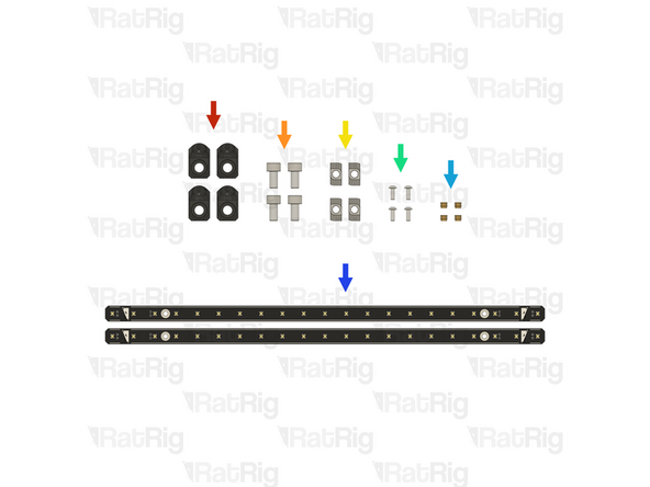
4x vc4_trim_front
-
4x vc4_trim_rear
-
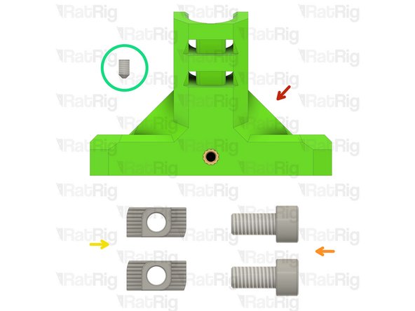
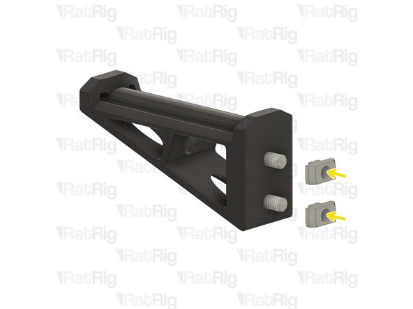
1x vc4_umbilical_frame
-
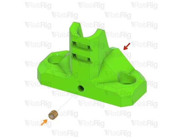
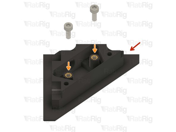
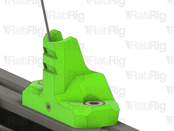
1x vc4_y_endstop_mount
-
-
-
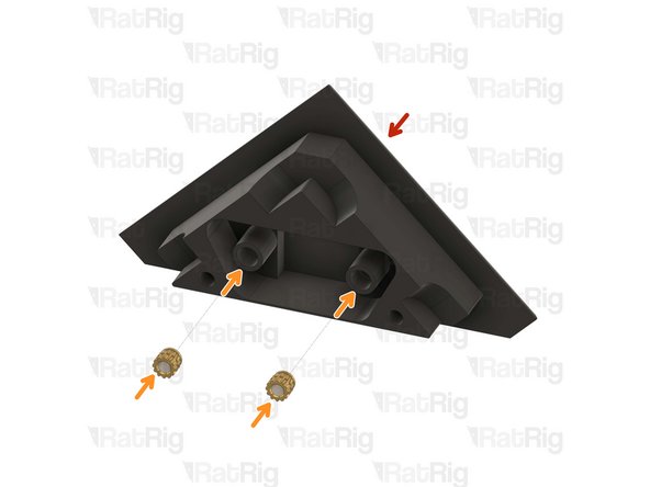
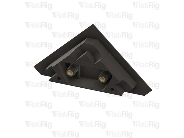
1x vc4_trim_front
-
2x Heat Insert M3
-
Repeat this step until all four parts have the heat inserts in place.
-
-
-
1x vc4_trim_rear
-
2x Heat Insert M3
-
Repeat this step until all four parts have the heat inserts in place.
-
-
-
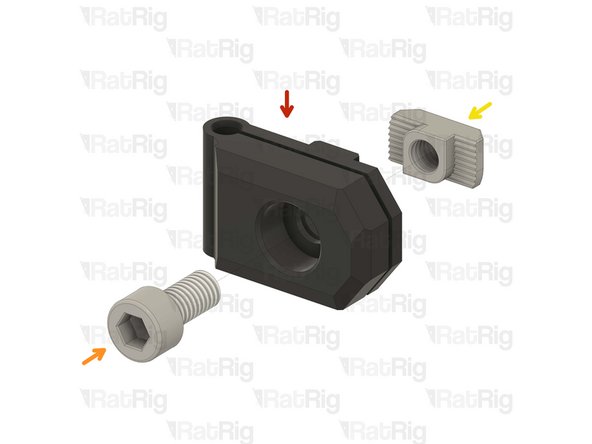
1x vc4_umbilical_frame
-
2x M6x12 Cap Head Screw
-
2x 3030 Drop-in T-Nut - M6
-
1x M3x5 Set Screw
-
-
-
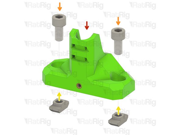
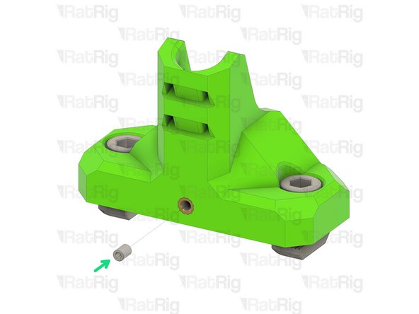
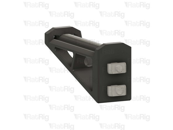
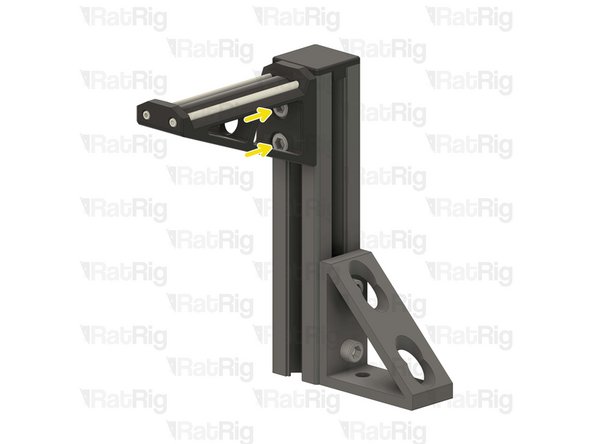
vc4_umbilical_frame
-
2x M6x12 Cap Head Screw
-
Install the M6 cap head screws into the umbilical frame as shown.
-
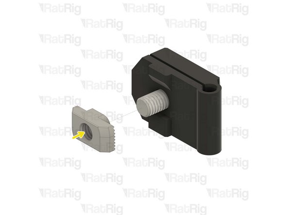
2x 3030 Drop-in T-Nut - M6
-
Loosely thread a 3030 T-Nuts onto the M6x12 screws. Do not tighten it at this point.
-
1x M3x5 Set Screw
-
-
-
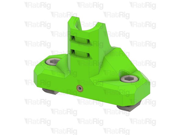
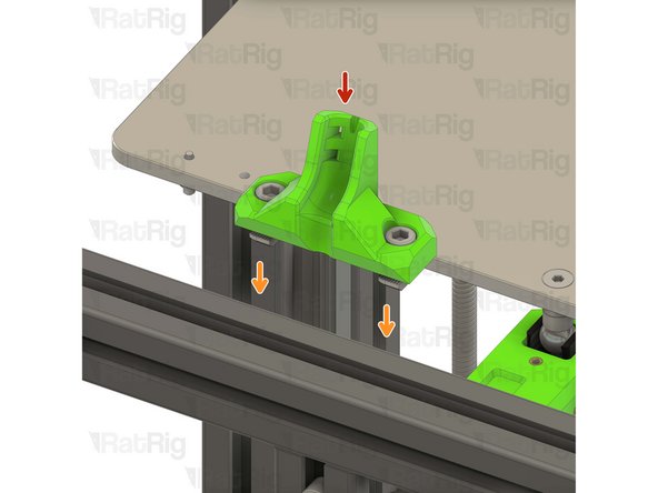
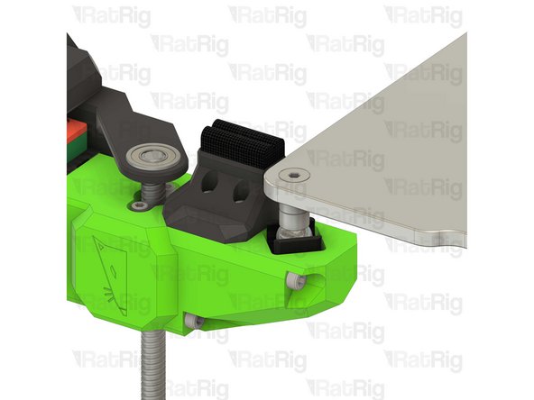
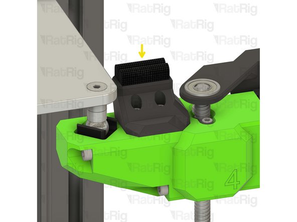
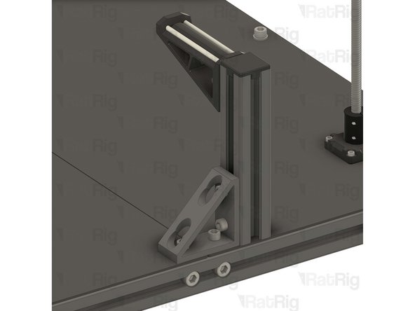
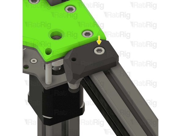
Umbilical frame assembly
-
Install the umbilical guide assembly to the V-Core 4 frame as shown.
-
Check that the printed part is seated in the middle of the frame.
-
Tighten the M6x12 screws to secure the umbilical frame.
-
Take care not to over-tighten the M6x12 screws as you can damage the printed parts
-
-
-
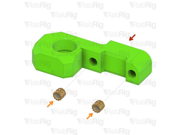
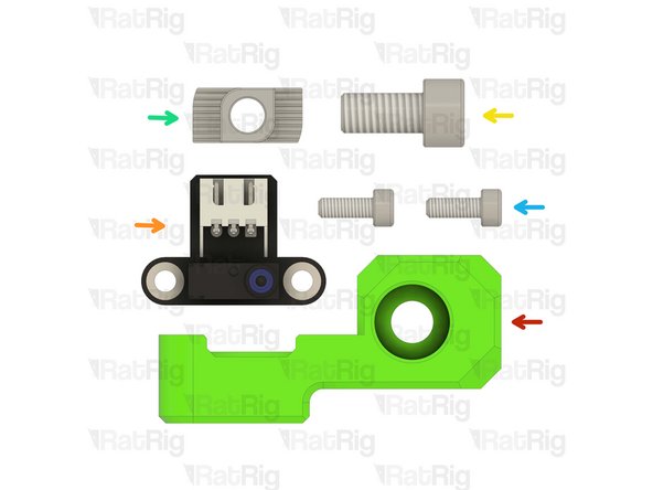
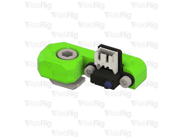
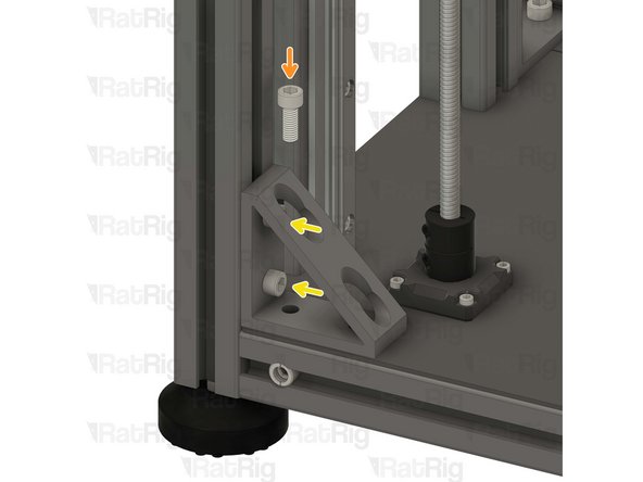
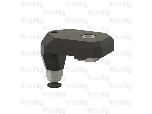
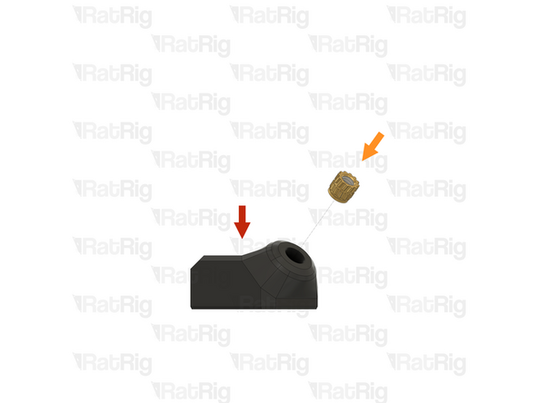
1x vc4_y_endstop_mount
-
1x Rat Rig Endstop
-
1x M6x12 Cap Head Screw
-
1x 3030 Drop-in T-Nut - M6
-
2x M3x8 Cap Head Screw
-
-
-
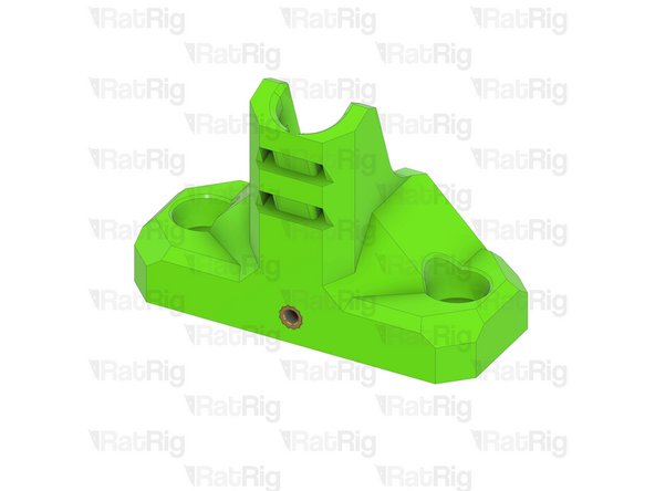
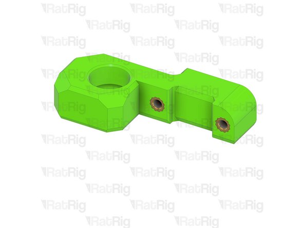
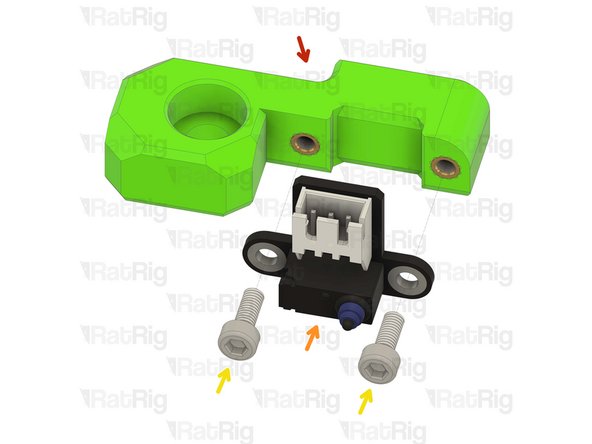
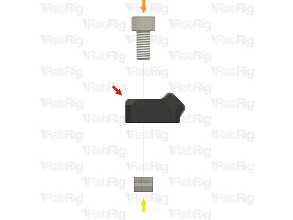
vc4_y_endstop_mount
-
Rat Rig Endstop
-
2x M3x8 Cap Head Screw
-
Tighten the M3x8 screws to secure the endstop to the printed part. Take care not to over tighten as you can damage the printed parts.
-
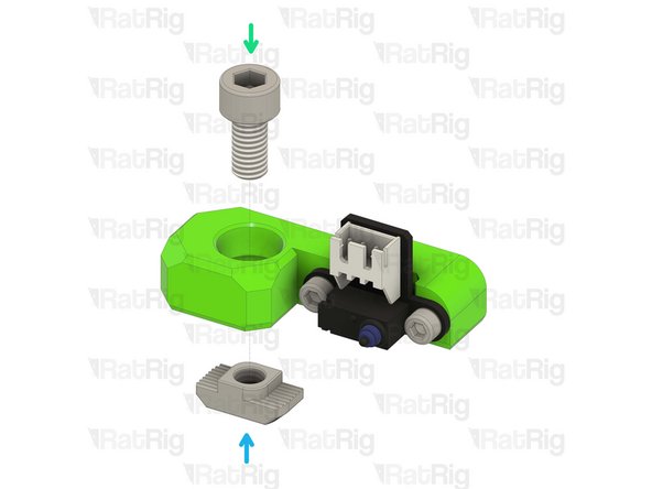
1x M6x12 Cap Head Screw
-
Install the M6 cap head screw into the Y endstop mount as shown.
-
1x 3030 Drop-in T-Nut - M6
-
Loosely thread a 3030 T-Nut onto the M6x12 screw. Do not tighten it at this point.
-
-
-
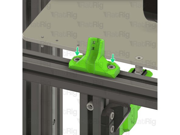
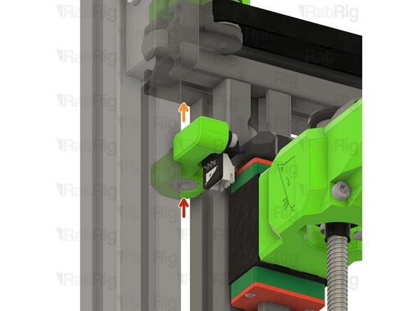
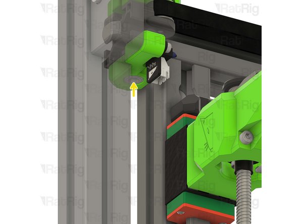
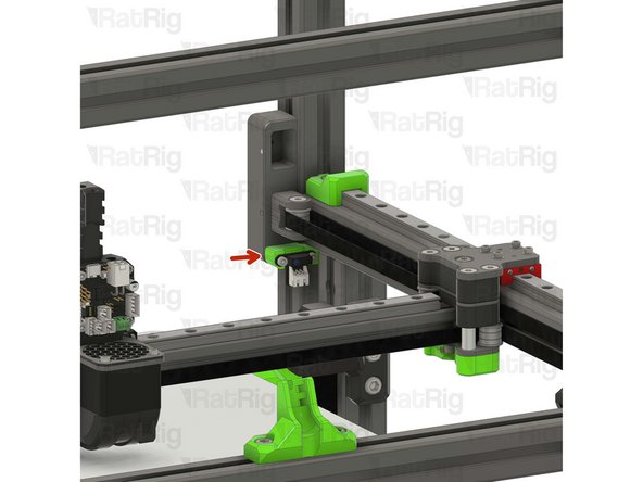
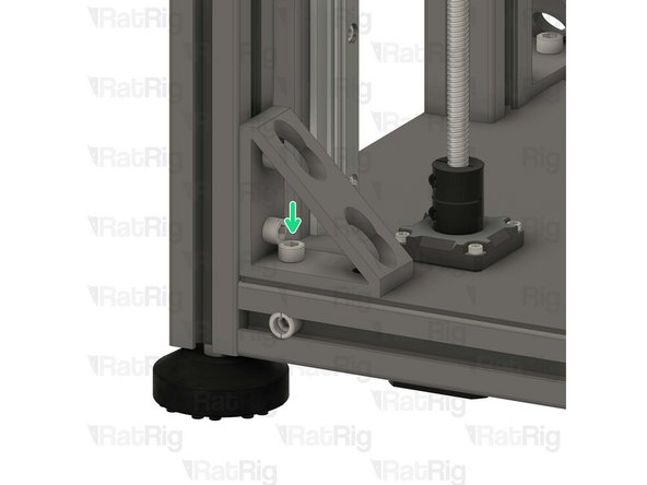
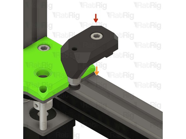
Y endstop mount assembly
-
Install the Y endstop mount assembly to the left side of the V-Core 4 frame as shown.
-
Tighten the M6x12 screw to secure the Y endstop mount.
-
Take care not to over-tighten the M6x12 screws as you can damage the printed parts
-
-
-
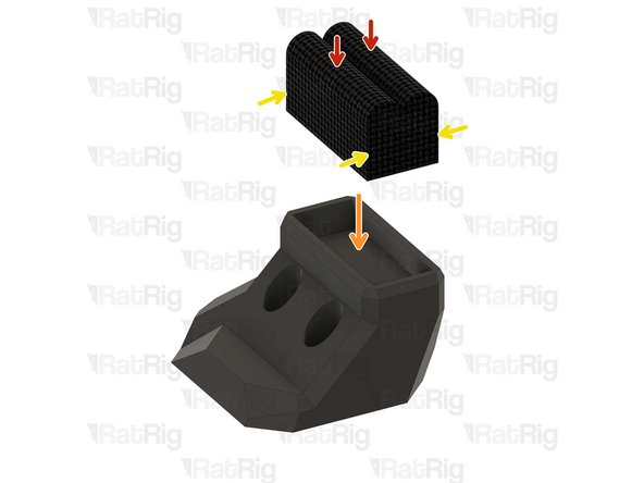
1x vc4_wiper_left
-
1x vc4_wiper_right
-
4x M3x8 Cap Head Screw
-
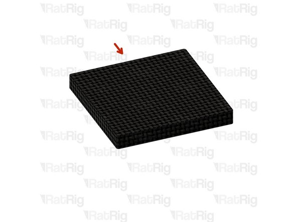
4x Felt Pad - 25x25x3mm
-
-
-
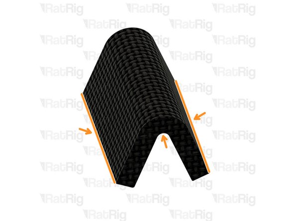
Felt Pad - 25x25x3mm
-
Peel the white paper on the back of the felt pads.
-
Bend all of the four felt pads as shown in order to insert them into the wiper housings.
-
Prepare four pads for the next step.
-
-
-
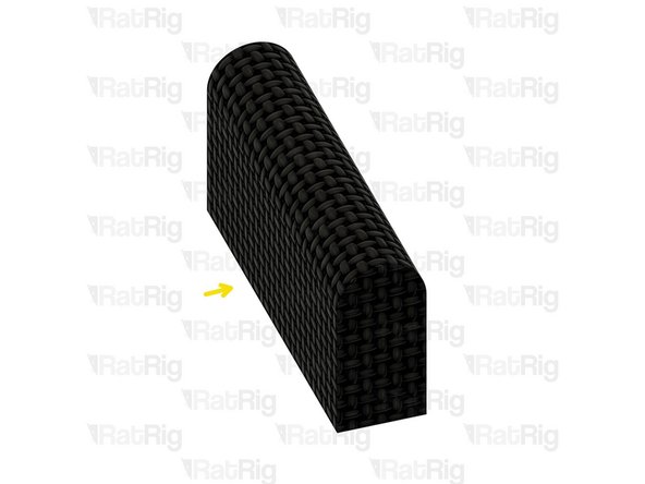
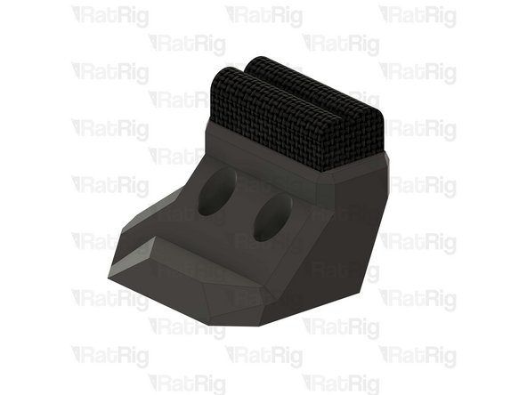
2x Felt Pad - 25x25x3mm
-
1x vc4_wiper_left
-
Squeeze two bent felt pads together while inserting them into the wiper body.
-
Repeat this step for the other wiper housing as well.
-
-
-
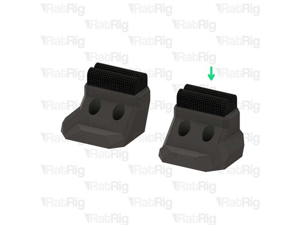
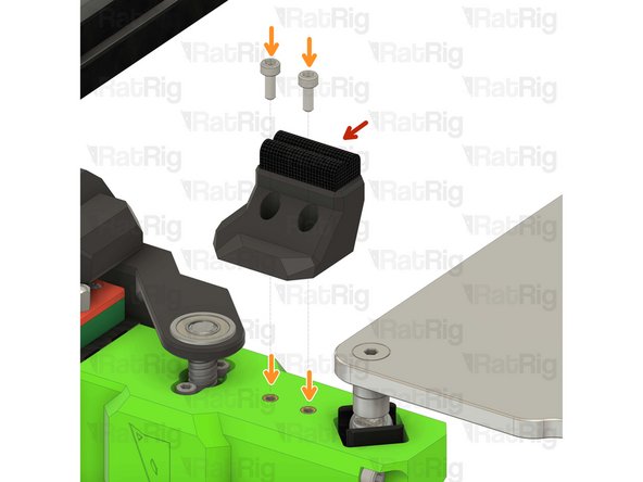
Left nozzle wiper
-
2x M3x8 Cap Head Screw
-
Secure the nozzle wiper to the bed arm as shown.
-
Take care not to over tighten the M3x8 screws as you can damage the printed parts.
-
Repeat this step to attach the opposite side nozzle wiper.
-
-
-
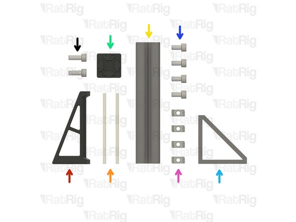
1x vc4_spoolholder_arm
-
2x 87mm PTFE Tube
-
1x T-Slot 3030 extrusion- 150mm
-
1x 3030_end_cap
-
1x Extruded 90° Corner- 6030 Tall
-
4x M6x12 Cap Head Screw
-
4x 3030 Drop-in T-Nut - M6
-
2x M6x16 Cap Head Screw
-
-
-
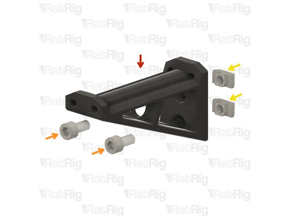
vc4_spoolholder_arm
-
2x M6x12 Cap Head Screw
-
2x 3030 Drop-in T-Nut - M6
-
Install the M6x12 Cap head screws into the spool holder as shown.
-
Loosely thread a 3030 T-Nuts onto the M6x12 screws. Do not tighten it at this point.
-
-
-
vc4_spoolholder_arm
-
87mm length of PTFE tubing
-
Using a sharp blade (such as a utility knife), cut two lengths of PTFE tubing measuring 87mm in length.
-
Insert a length of PTFE into each channel of the spool holder as shown.
-
-
-
1x Extruded 90° Corner- 6030 Tall
-
2x M6x12 Cap Head Screw
-
2x 3030 Drop-in T-Nut - M6
-
Install the M6 cap head screws into the corner bracket as shown.
-
Loosely thread a 3030 T-Nuts onto the M6x12 screws. Do not tighten it at this point.
-
-
-
T-Slot 3030 extrusion- 150mm
-
Corner bracket assembly from the previous Step
-
Attach the corner bracket assembly to the aluminium extrusion, aligning the flat edges together.
-
3030_end_cap
-
Place the printed cap on the other end.
-
Tighten the M6x12 screws to secure the corner bracket to the extrusion.
-
Ensure the extrusion is flush with the corner bracket
-
-
-
Spool holder printed part
-
T-Slot 3030 extrusion- 150mm
-
Attach the spool holder printed part to the aluminium extrusion as shown, aligning the top edges.
-
Tighten the M6x12 screw to secure the spool holder to the extrusion.
-
Take care not to over tighten the screws as you can damage the printed parts.
-
-
-
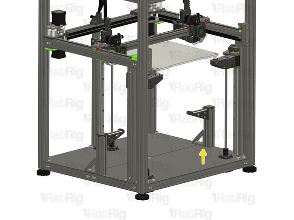
The spool holder can be mounted on either side of the machine, this guide will instruct you to install it on the left side of the machine for single-head configuration.
-
2x M6x12 Cap Head Screw
-
2x M6 Washer
-
Remove the shown M6x12 screws and their corresponding washers in order to allow for the spool holder arm to be installed.
-
Avoid moving the machine around or bumping into it, to prevent the t-nuts from moving.
-
-
-
Spool holder arm assembly from the previous Step
-
2x M6x12 Cap Head Screws removed from step 22
-
Align the corner bracket of the spool holder with the holes in the base plates.
-
Carefully tighten the M6x12 screws to the T-Nuts inside the base aluminum extrusion, securing the spool holder in place.
-
-
-
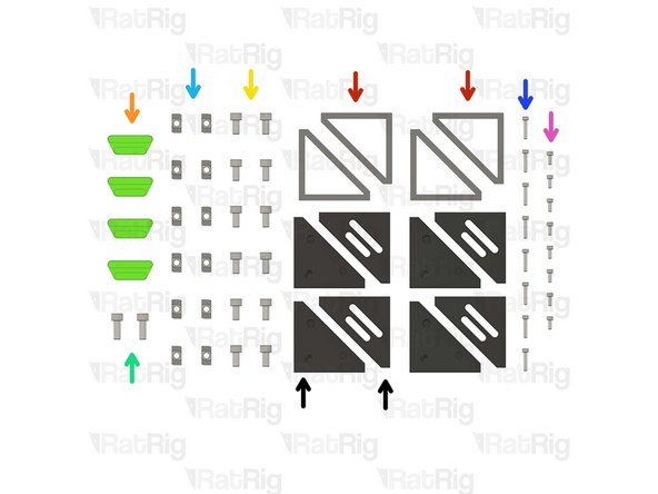
4x Extruded 90° Corner- 6030 Tall
-
4x vc4_trim_diffuser
-
12x M6x12 Cap Head Screw
-
2x M6x16 Cap Head Screw
-
12x 3030 Drop-in T-Nut - M6
-
8x M3x16 Cap Head Screw
-
8x M3x8 Cap Head Screw
-
4x vc4_trim_front + 4x vc4_trim_rear
-
-
-
vc4_trim_rear
-
2x M3x8 Cap Head Screw
-
These screws will be used to hold an Led PCB module, coming soon
-
Prepare the four assemblies.
-
-
-
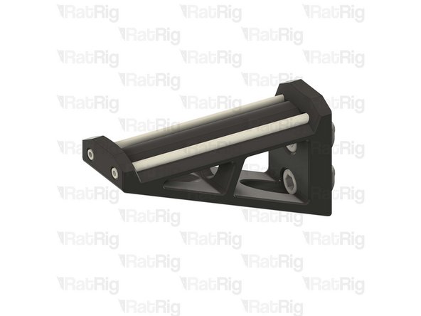
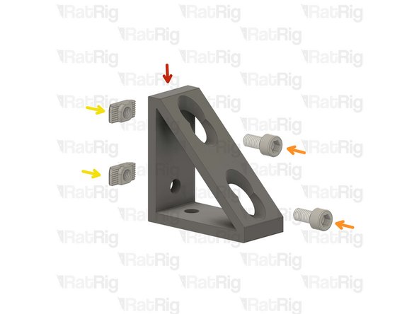
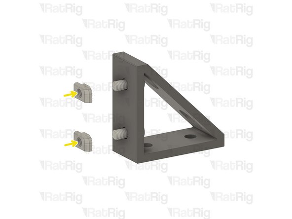
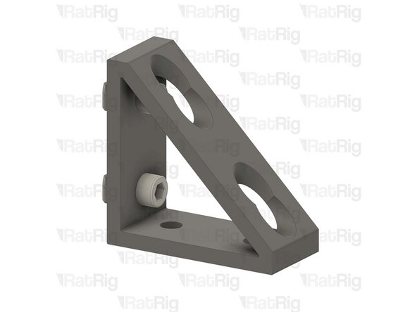
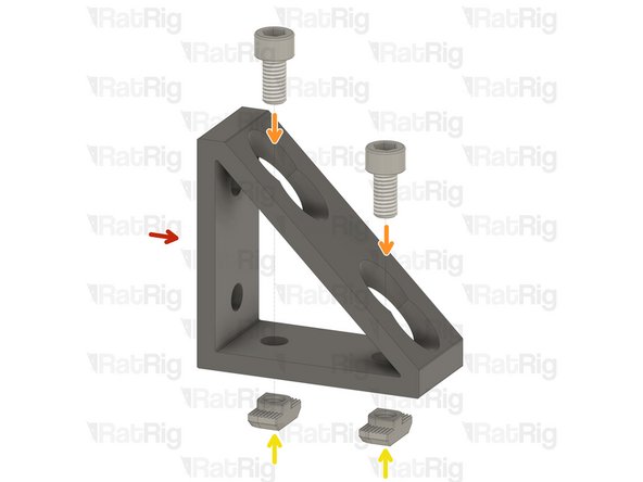
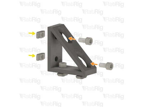
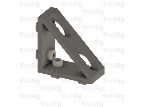
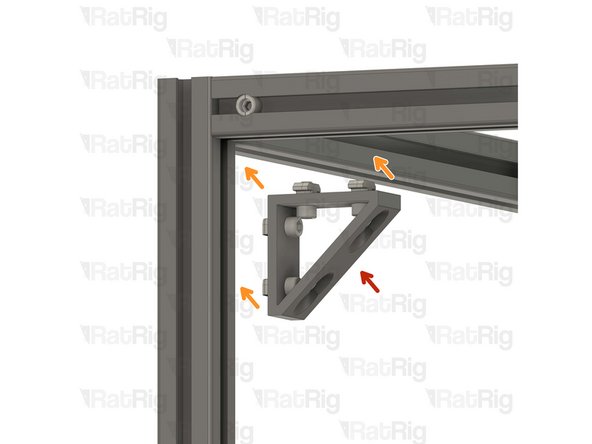
Extruded 90° Corner- 6030 Tall
-
4x M6x12 Cap Head Screw
-
4x 3030 Drop-in T-Nut - M6
-
Install the M6 cap head screws into the corner bracket as shown.
-
Loosely thread a 3030 T-Nuts onto the M6x12 screws. Do not tighten it at this point.
-
Repeat this step one more time, then go back and follow through Step 19 twice with the remaining corner brackets.
-
-
-
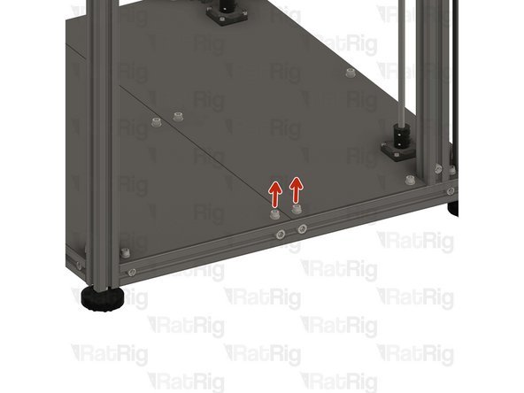
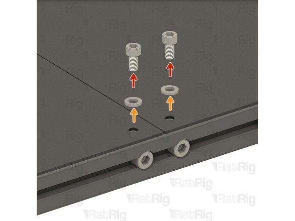
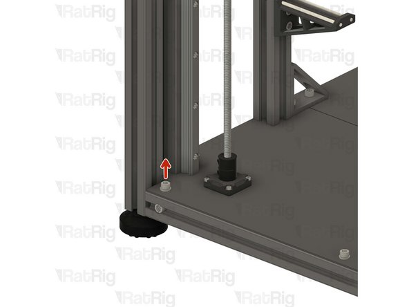
1x M6x12 Cap Head Screw
-
1x M6 Washer
-
Remove the highlighted M6x12 screw and the corresponding washer in order to allow for the lower corner bracket assembly to be installed.
-
-
-
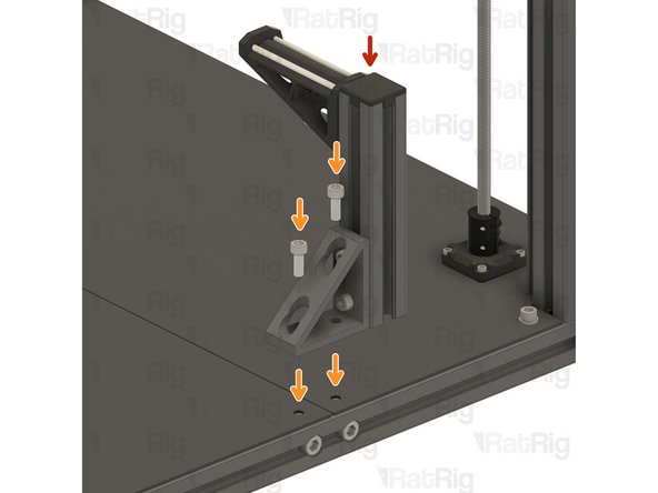
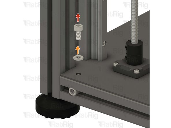
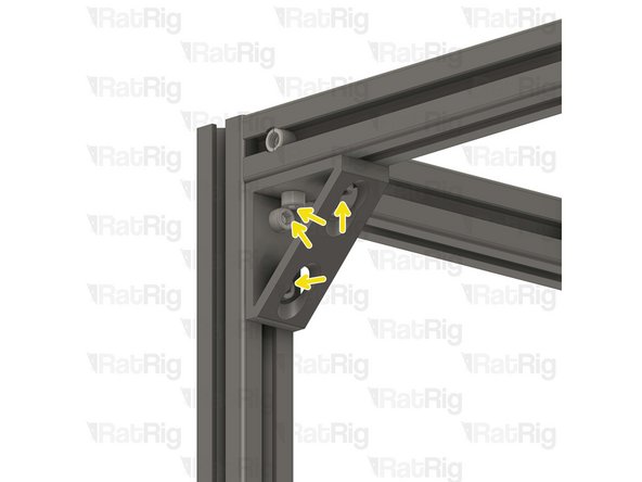
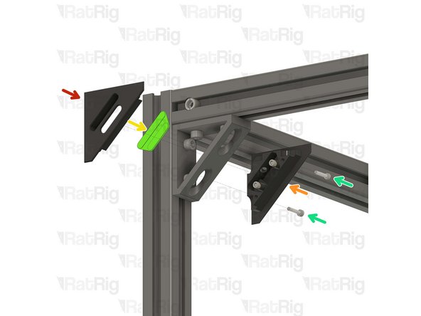
Lower corner bracket assembly
-
1x M6x16 Cap Head Screw
-
Install the lower corner bracket to the V-Core 4 frame as shown.
-
Tighten the M6x12 screws to attach the bracket.
-
Carefully tighten the M6x16 screw to the T-Nut inside the base aluminium extrusion, securing the bracket in place.
-
-
-
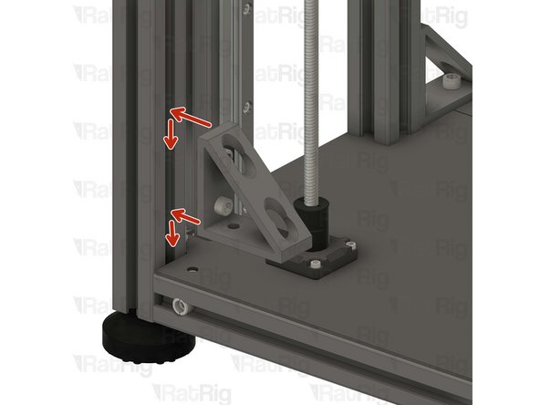
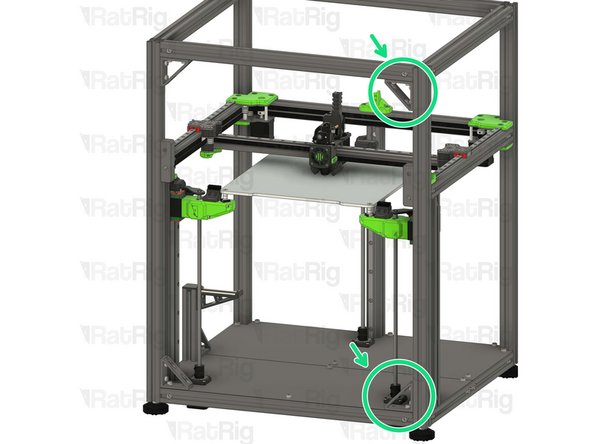
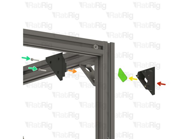
Upper corner bracket assembly
-
Install the upper corner bracket to the V-Core 4 frame as shown.
-
Tighten the M6x12 screws to secure the bracket to the frame.
-
Repeat Steps 27, 28 and 29 to attach the rest of the brackets to the other side.
-
-
-
1x vc4_trim_front
-
1x vc4_trim_rear
-
1x vc4_trim_diffuser
-
2x M3x16 Cap Head Screw
-
Tighten the M3x16 screws into the front trim printed part, inserting them through the rear trim printed part.
-
Sandwich the parts together enclosing the diffuser inside the corner bracket.
-
Take care not to over tighten the screws as you can damage the printed parts.
-
-
-
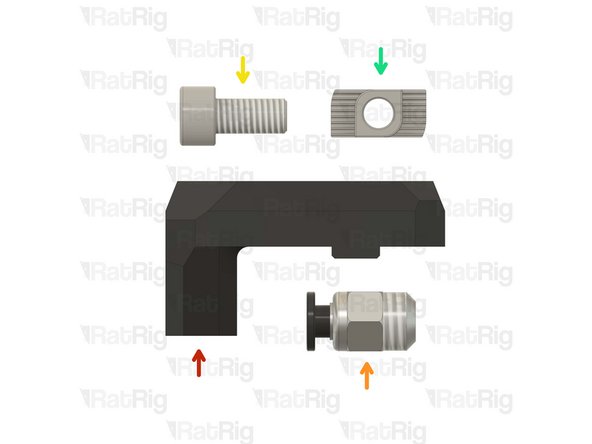
1x vc4_ptfe_guide_upper
-
1x Bowden Pass-through Adaptor
-
1x M6x12 Cap Head Screw
-
1x 3030 Drop-in T-Nut - M6
-
-
-
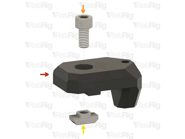
vc4_ptfe_guide_upper
-
1x M6x12 Cap Head Screw
-
Install the screw into the PTFE guide as shown.
-
1x 3030 Drop-in T-Nut - M6
-
Loosely thread a 3030 T-Nut onto the M6x12 screw. Do not tighten it at this point.
-
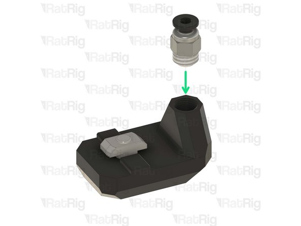
Bowden Pass-through Adaptor
-
Thread the bowden adapter into the printed part and secure it in place.
-
Take care not to over tighten the bowden adapter as you can damage the printed parts.
-
-
-
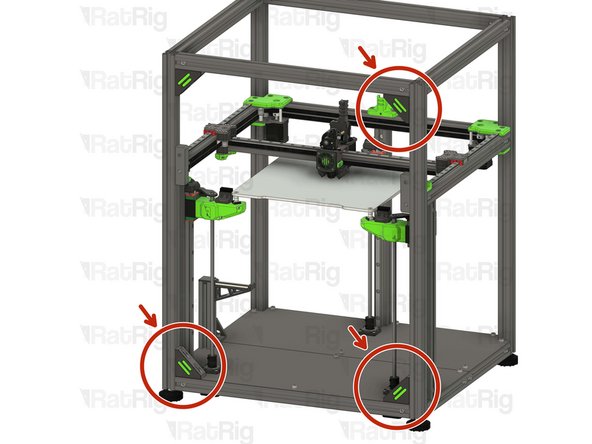
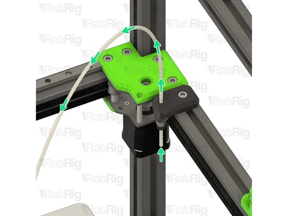
Upper PTFE guide assembly
-
Install the PTFE guide assembly to the left back side of the V-Core 4 frame as shown.
-
Tighten the M6x12 screw to secure the upper PTFE guide.
-
Insert the PTFE tubing through the bowden clamp, as shown. Then connect it to the orbiter extruder.
-
Take care not to over tighten the screws as you can damage the printed parts.
-
-
-
2x vc4_ptfe_guide_lower
-
2x M6x12 Cap Head Screw
-
2x 3030 Drop-in T-Nut - M6
-
-
-
vc4_ptfe_guide_lower
-
1x M6x12 Cap Head Screw
-
Install the M6 cap head screw into the PTFE guide as shown.
-
1x 3030 Drop-in T-Nut - M6
-
Loosely thread a 3030 T-Nut onto the M6x12 screws. Do not tighten it at this point
-
Repeat this step one more time to assemble the other PTFE guide.
-
-
-
2x Lower PTFE guide assembly from the previous Step
-
Position the PTFE guide assemblies on the left side of the V-Core 4 frame.
-
Insert the PTFE tubing into the guides, as shown.
-
Tighten the M6x12 screw to secure the guide assemblies and PTFE to the frame.
-
Take care not to over tighten the screws as you can damage the printed parts.
-
-
-
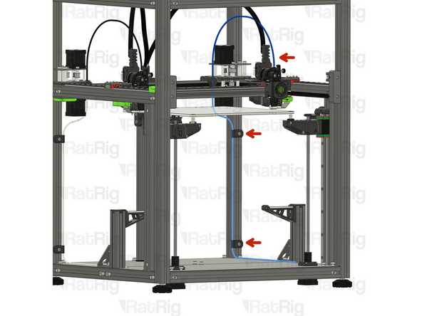
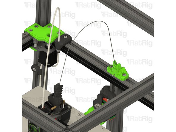
It is recommended to route the PTFE filament guide as shown.
-
If you are assembling the IDEX, go back to Step 32 and complete an additional filament path assembly, on the opposite side of the machine.
-
-
-
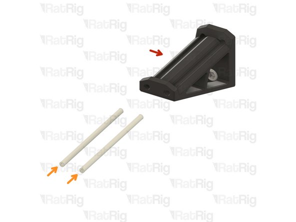
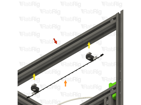
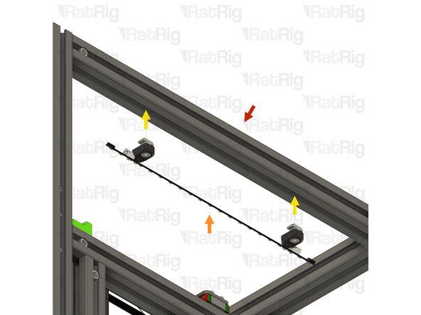
Piano Wire for Umbilical - 1000mm x 1.00mm
-
M3x5 Set Screw
-
The Piano wire need to be cut to length for you machine:
-
V-Core 4 300 - 650mm
-
V-Core 4 400 - 750mm
-
V-Core 4 500 - 850mm
-
Use a strong set of cutting pliers, as the piano wire is super stiff and can break small pliers.
-
-
-
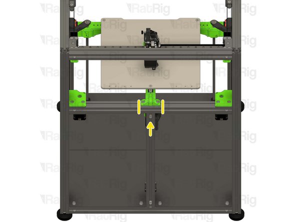
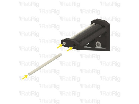
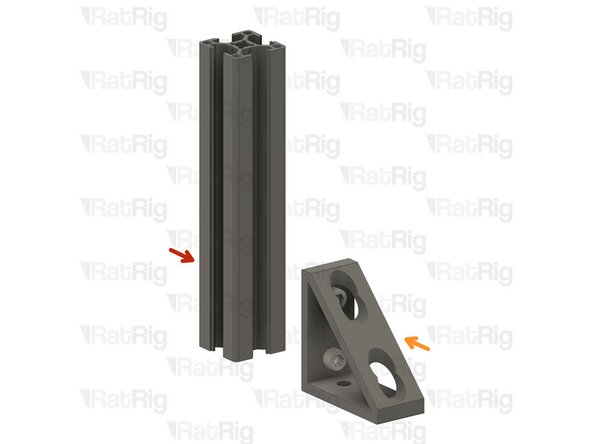
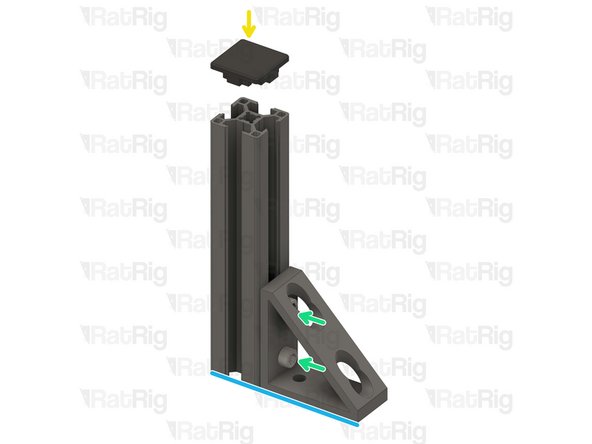
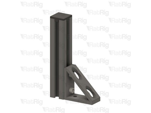
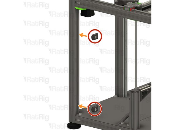
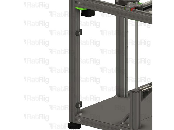
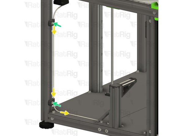
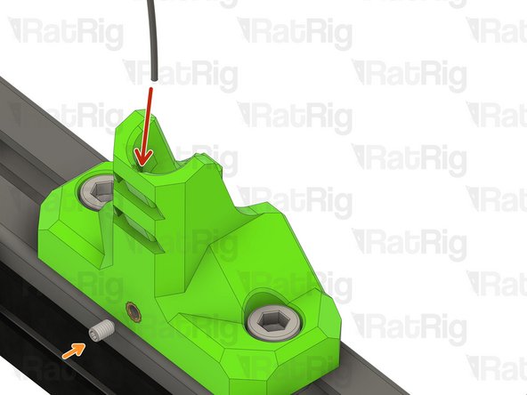
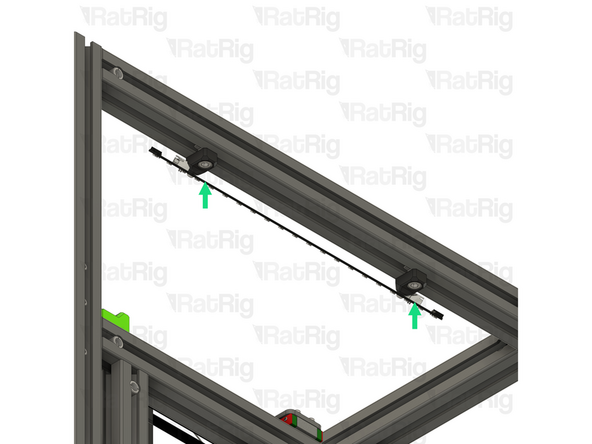
Insert the piano wire into the designated hole in the vc4_umbilical_frame printed part
-
thread the M3x5 set screw to secure the Piano wire in place
-
-
-
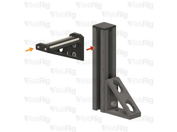
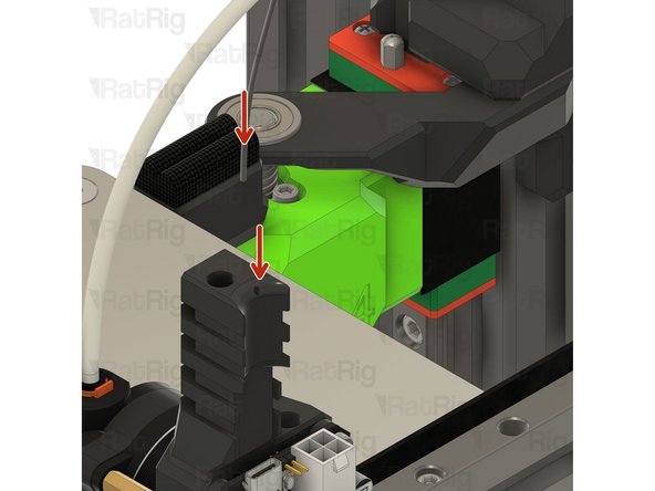
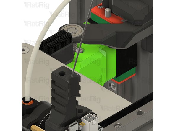
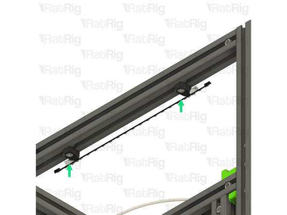
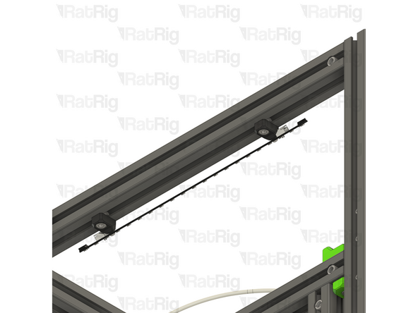
Insert the other end of the piano wire in the designated hole on the EBB toolboard mount
-
Be careful, the piano wire is super stiff, do not allow it to swing freely as it can hit you and create injury.
-
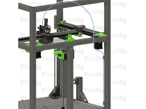
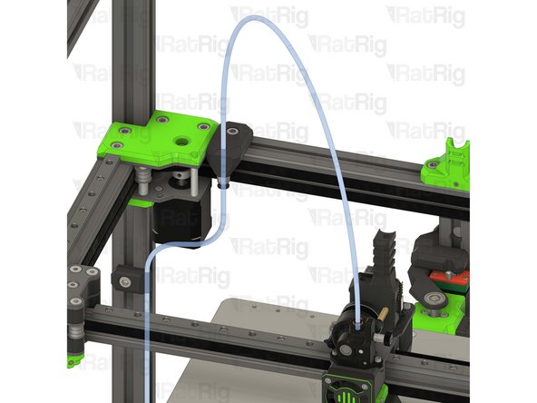
Once installed it should look like the picture, the piano wire will provide support to the USB and power cables, improving Input shaper results
-
-
-
4x vc4_led_holder_frame printed part
-
4x M6x12 Cap Head Screw
-
4x 3030 Drop-in T-Nut - M6
-
4x M3x8 Button Head Screw
-
4x M3 heat insert
-
2x Rat Rig Dayspring LED strip - 310mm
-
-
-
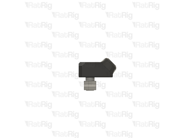
1x vc4_led_holder_frame
-
1x M3 heat insert
-
Install a heat insert into the printed part as shown
-
Prepare four of these parts
-
-
-
LED frame mount from the previous step
-
1x M6x12 Cap Head Screw
-
Insert an M6 cap head screw into the printed part as shown
-
1x 3030 Drop-in T-Nut - M6
-
Loosely thread a 3030 T-Nut onto the M6x12 screws. Do not tighten it at this point
-
Prepare four of these parts
-
-
-
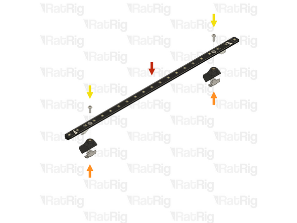
1x Rat Rig Dayspring LED strip - 310mm
-
2x LED frame mount from the previous step
-
Align a frame mount assembly with mounting hole on the LED strip
-
2x M3x8 Button Head Screw
-
Insert an M3x8 button head screw through the mounting hole in the LED strip and screw it into the printed mount
-
Assemble two LED strips
-
-
-
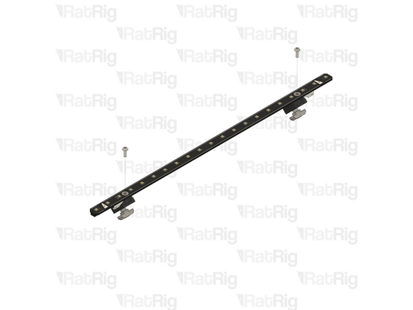
Rat Rig V-Core 4.0 assembly - Left side
-
1x LED strip assembly from the previous step
-
Align the LED strip mounts with the frame, making sure both T-nuts slot into the extrusion slots
-
Secure the LED strip to the frame by tightening both M6x12 screws
-
Take care not to overtighten the screws as you can damage the printed parts
-
-
-
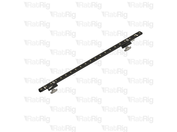
Rat Rig V-Core 4.0 assembly - Right side
-
1x LED strip assembly from the step 45
-
Align the LED strip mounts with the frame, making sure both T-nuts slot into the extrusion slots
-
Secure the LED strip to the frame by tightening both M6x12 screws
-
Take care not to overtighten the screws as you can damage the printed parts
-


Cancel: I did not complete this guide.
34 other people completed this guide.

One Comment
Im IDEX mode due i Not need a second Piano wire for the other printhead? There is only one wire
ds3975@gmail.com - Open Reply