Reputation over time
It looks like this user hasn't gained any reputation yet.
Once they have, you'll be able to view a graph of their reputation gained over time.
Here's a preview of what the graph will look like:
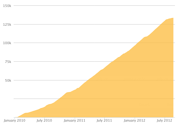
Reputation Breakdown
No reputation gained yet.
199
Now is a good time to double check that the Z rails are not touching the motor mounts. You put them 1 or 2 mm above the motor mounts in a previous section.
Now is a good time to double check that each of the three 3030 extrusion involved goes strait up and are perpendicular to the bottom of the frame where they are attached. If they are not close to going straight up then it will be difficult or impossible to complete the alignments in the remainder of this step.
This step now starts by: Installing the three lead screws through the lead screw nuts. This is done by screwing the lead screw into the lead screw nut from above. The lead screw will first go through the top of the lead screw nut and continues below the lead screw nut. The lead screw is then inserted into the motor coupler that was previously attached during the “motor mounts” section. It should make solid contact with the bottom of the coupler. The grub screw on the coupler is then used to tighten the coupler to the lead screw. The lead screw should now spin about the axis of the motor and the axis of the coupler. The rest of this step is to ensure that the lead screw is parallel to the rail so the bed arm moves strait up the rail without sideways movement (X axis or Y axis) as it goes from the bottom to the top.
This has been fixed in this documentation. Attaching the lead screws is performed later and this step is now about “attaching the arms” to the frame. Ignore the lead screws that appear in the graphic of this step.
This swap has occurred in this documentation. You can now “attach the arms” in this step and “attach strain relief” in the next step as David and Daniel suggested.
This cable strain relief will accept three nylon wire ties in the future. They each go in one of the rectangular holes, curve 90 degrees inside the plastic strain relief and then come out another rectangular hole. Now is a good time to run a small wire tie through each of these holes to make sure they are properly cleaned out.
This problem has been fixed. What used to be the next step (attach the arms to the frames) now happens before this step.
The lead screw nut blocks may appear to have different orientations with respect to the bed_arms. The orientation shown in the graphic always has the side of the nut block with two holes on the same side of the plastic bed_arms as the magnet. These two holes will be facing upwards towards the bed when the bed is placed on the bed_arms in a later step. The opening (gap) in the nut block may point toward the magnet or away from the magnet. The nut blocks will extend above the bed_arms but they will not interfere with the bed when the printer is operating.
The lead screw nut blocks have two sides. One side has a hexagonal recess to accept the 5mm locking nuts. Press the locking nuts into these recesses before mounting the nut block to the bed_arms. The “Pulling nuts from the back“ technique described in section 00 works well here.
Keep the three 5mm adjustment screws (AKA grub screws) and the three 5mm square nuts that come in the package with the nut blocks. These may be needed on your printer in the future to mitigate Z wobble by turning these nut blocks into anti-backlash nuts. They will not be installed or adjusted in this build guide. These items may be needed when you are tuning your printer.
Page 1 of 3
Next