-
-
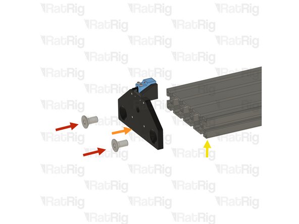
T-Slot extrusion 40120 - 522mm
-
Rat Rig Mill - 4160 Bearing end plate
-
Rat Rig Mill - X 40160 Plate
-
4x M12x25 Countersink screws
-
2x M3x30 Cap Head Screws
-
2x M3x16 Cap Head Screw
-
SN04-N2 Proximity Sensor
-
mill_x_endstop_mount printed part
-
-
-
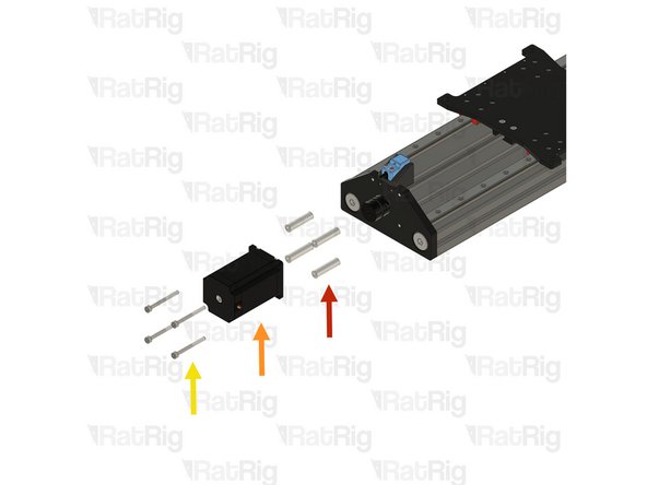
2x M3x16 Cap Head Screw
-
SN04-N2 Proximity Sensor
-
mill_x_endstop_mount printed part
-
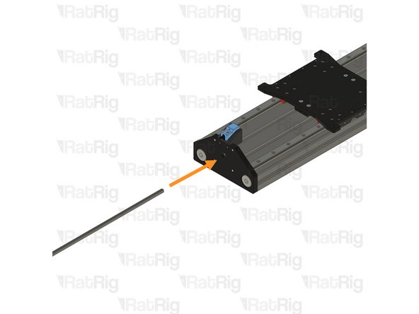
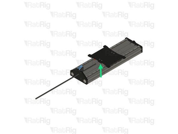
X endstop assembly
-
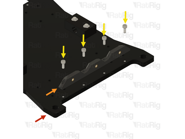
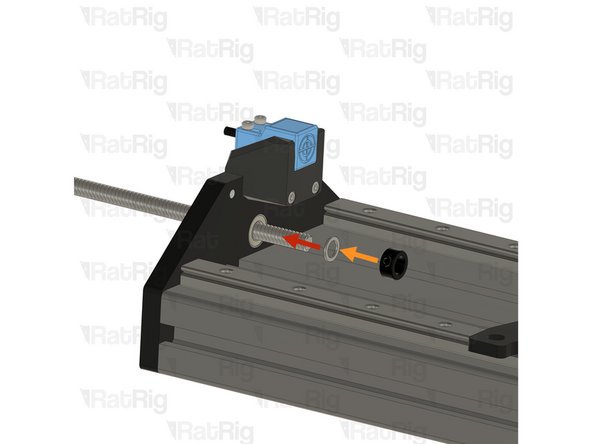
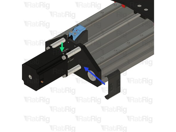
2x M3x30 Cap Head Screws
-
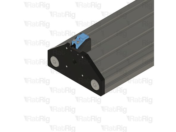
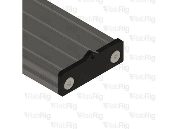
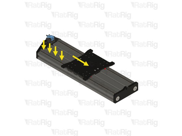
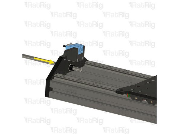
The endstop will be mounted with M3x30 cap head screw, on to the shown threaded holes.
-
Make sure the endstop is facing the same side as the bearing groove.
-
-
-
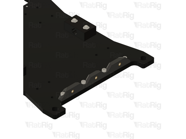
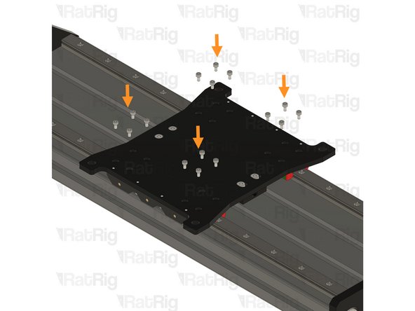
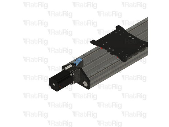
2x M12x25 Countersink screws
-
Rat Rig Mill - X 40160 Plate
-
T-Slot extrusion 40120 - 522mm
-
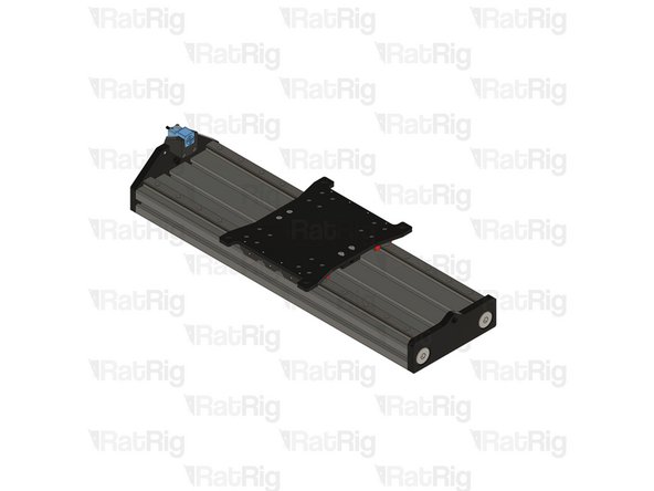
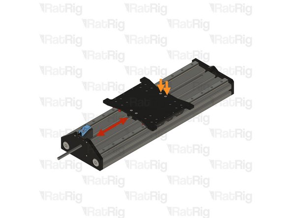
Secure the plate to one end of the extrusion as shown.
-
-
-
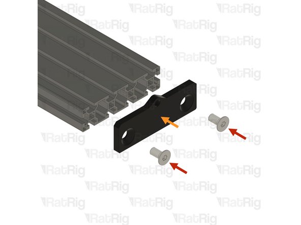
2x M12x25 Countersink screws
-
Rat Rig Mill - 4160 Bearing end plate
-
Secure the plate to one end of the extrusion as shown.
-
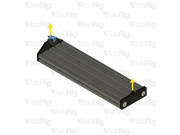
Ensure both plates are facing the same way
-
-
-
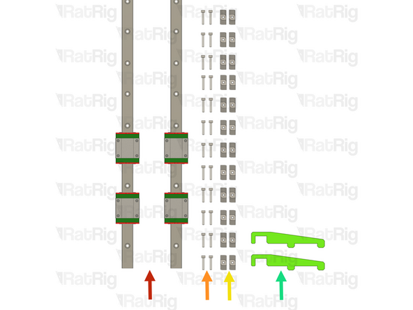
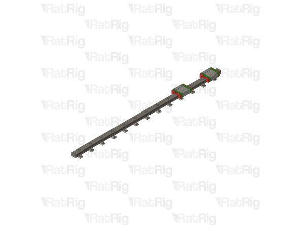
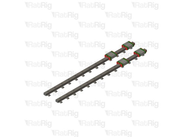
2x Linear Rail - MGN15 420mm + 2 x MGN15C carriage
-
20x M3x16 Cap Head screws
-
20x 4040 Drop-in T-Nut - M3
-
2x align_40120_mgn15 printed part
-
-
-
The linear rails are supplied with a protective oil coating on them. It is strongly recommended to prepare your work surface with paper towels and to wear disposable gloves.
-
Paper Towels
-
Linear Rail
-
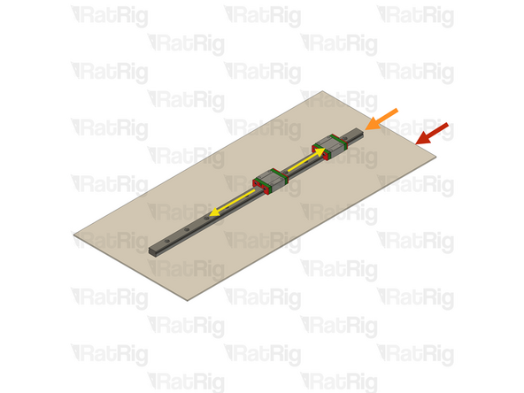
With the rail still on the absorbent paper towels, carefully and slowly move the carriage from one end of the rail to the other
-
Small changes in resistance are normal, but the carriage becoming very hard to push, or binding completely are not
-
If the carriage does not move smoothly, or binds completely, refer to the Linear Rail Troubleshooting Guide
-
The linear rail carriages are not interchangeable. Do not try to use a carriage on a different linear rail than the one it was supplied with.
-
Check this guide if one or more carriages don't move smoothly.
-
-
-
Do not allow the linear rail carriages to leave the end of the rail at any point
-
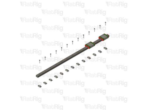
MGN15 Linear Rail
-
Insert an M3x16 cap head screw in each of the holes on the linear rail
-
Loosely thread a 4040 T-Nut on to each of the M3x16 screws
-
Repeat these instructions for the second linear rail
-
-
-
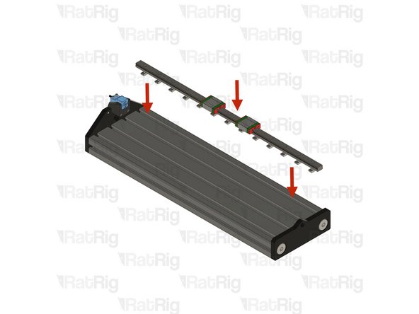
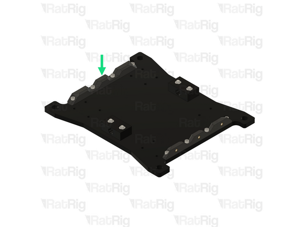
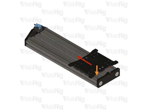
Place one X linear rail assembly on the designated T-slot.
-
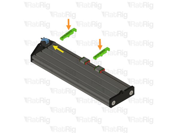
Insert the two align_40120_mgn15 printed jigs in the T-Slot and rail.
-
Ensure the Y rail is sitting flush against the Mill front Y plate.
-
Make sure the align_40120_mgn15 printed jigs are correctly placed and centering the rail on the T-slot
-
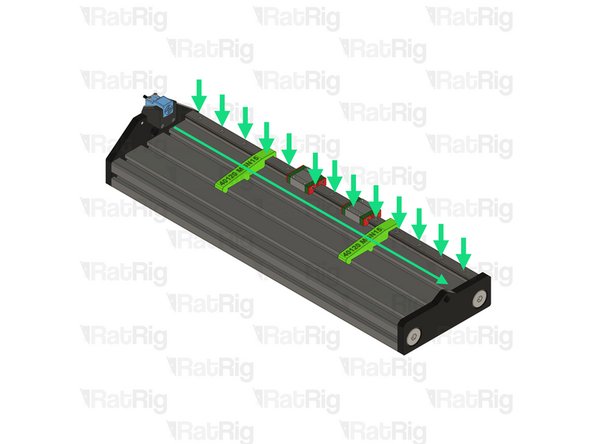
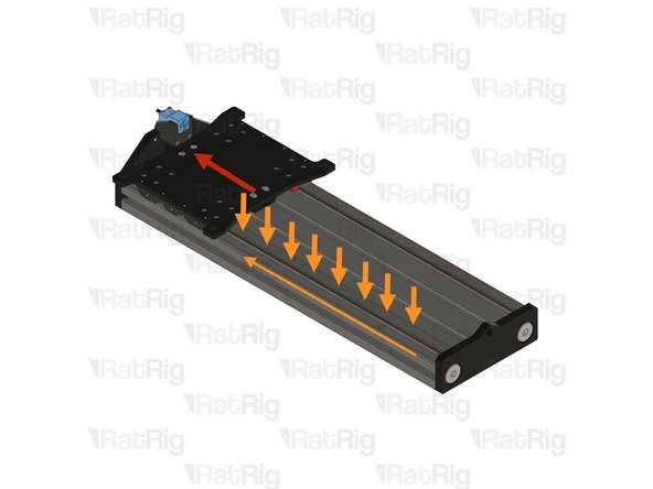
Tighten the linear rails screws one at a time starting from the front and making your way towards the back, one by one.
-
MGN15 Rails should be tightened to 98 N-cm of torque, overtightening the screws will result in rail binding.
-
-
-
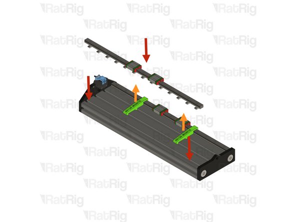
Place the second Y linear rail assembly on the T-slot but DO NOT tighten the screws.
-
Remove the two align_40120_mgn15 printed jigs
-
-
-
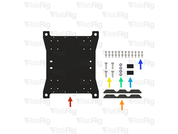
Rat Rig Mill - X Gantry Plate
-
2x mill_bellow_holder assembly
-
4x M5x16 Low Head Screw
-
4x M5 Nylon Locking Hex Nuts
-
2x Nut Block for TR8x8
-
Do not misplace the TR8x8 blocks with the TR8x4 blocks. If uncertain, test by threading them onto the TR8x8 lead screw
-
24x M3x6 Cap Head Screws
-
-
-
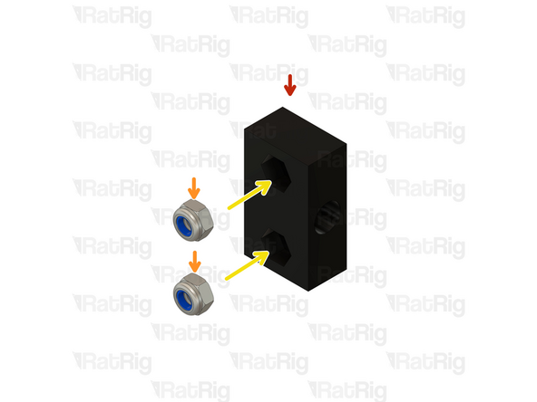
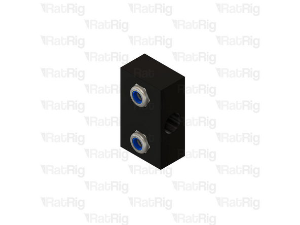
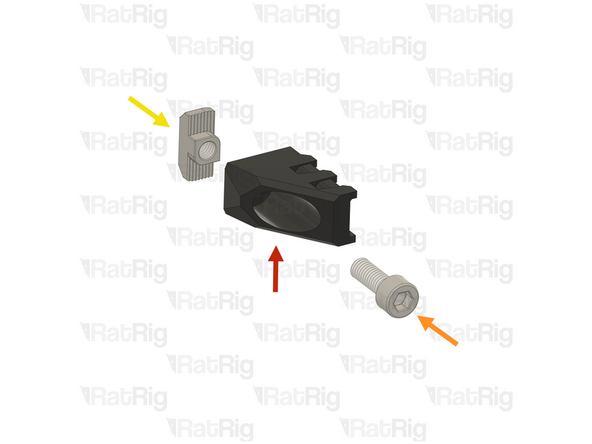
Nut Block for TR8x8
-
M5 Nylon Locking Hex Nut
-
Insert the M5 Locking Hex Nuts in to the Nut Block
-
Prepare two assemblies.
-
-
-
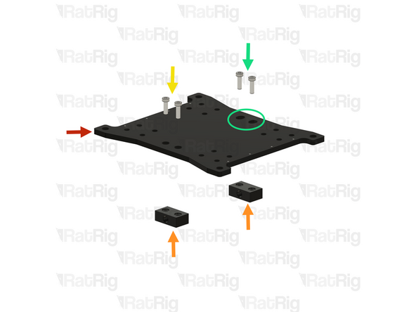
Rat Rig Mill - X Gantry Plate
-
Ensure that the X gantry plate is not mistaken for the Y gantry plate. The X gantry plate features M3 threaded holes along its edges, whereas the Y gantry plate does not.
-
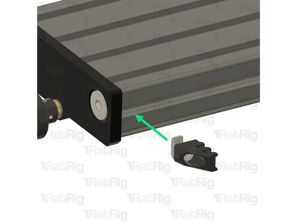
Nut Block for TR8x8 assembly from the last step.
-
The M5 Nylon Locking Hex Nuts, must be facing away from the Y gantry plate.
-
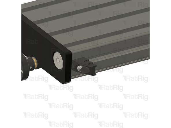
Gently tighten the M5x16 Low Head Screws on the designated holes.
-
Do not overtighten the screws as it will cause binding in the lead screw. Tighten until the nut block is flush with the plate and add half a turn on the screws.
-
Thread the M5x16 Low Head Screws on the designated slot, Do not tighten this Nut Block, it will be adjusted later.
-
These Screws must be installed on the M5 slot in the Y gantry plate.
-
-
-
Flip the X joiner assembly upside down.
-
mill_bellow_holder assembly
-
4x M3x6 Cap Head Screw
-
Do not overtighten the screws as you can damage the printed part.
-
Repeat the previous steps and install the second bellow holder.
-
-
-
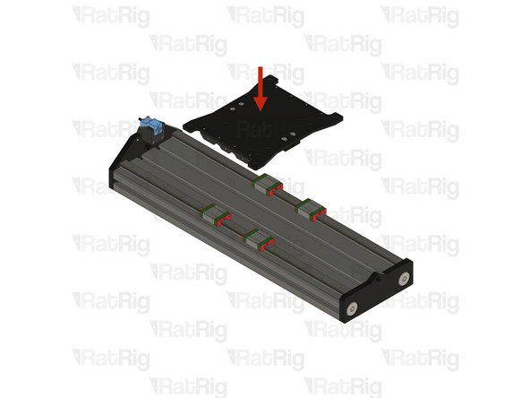
Install the X Joiner assembly on the linear rails, as shown.
-
Using the 16x M3x6 Cap Head screws, fasten the XY joiner plate assembly to the mgn15 carriages.
-
MGN15 Rails should be tightened to 98 N-cm of torque, overtightening the screws will result in rail binding.
-
Tip: Blue thread lock can be added to the thread of the M3x6 Cap Head screws.
-
-
-
While the second linear rail remains loose, the X plate should move smoothly without resistance. If you experience any binding or drag, slightly loosen the carriage screws, as they may be overtightened.
-
Be careful to ensure that the Y joiner plate carriages do not detach from the linear rail during the process.
-
Move the Y joiner fully to the front as demonstrated. Then, gradually move it toward the back, exposing one linear rail screw at a time, and tighten each screw as you progress.
-
Ensure that all linear rail screws are tightened from front to back. Avoid overtightening, as this may cause binding and restrict movement.
-
MGN15 Rails should be tightened to 98 N-cm of torque, overtightening the screws will result in rail binding.
-
Move the Y plate assembly slightly back to gain access to the last screws on the linear rail.
-
At this stage, the joiner plate should move back and forth smoothly. Test its movement to ensure it operates freely. If you encounter any resistance, adjust the screw tension as needed until the assembly moves without friction.
-
-
-
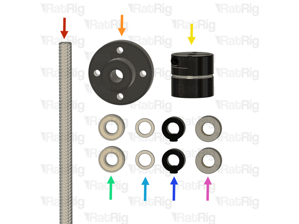
Leadscrew - TR8x8 Metric - 585mm
-
Jog Knob
-
Coupler - Disc Type
-
2x Ball Bearing 688ZZ
-
2x Shim - 12 x 8 x 1mm
-
2x Lock Collar
-
2x Thrust Bearing F8-16M
-
-
-
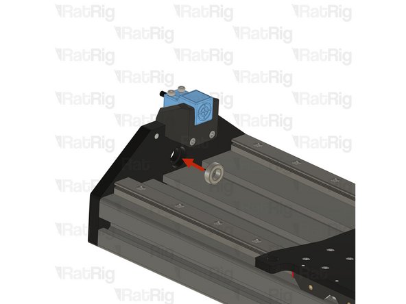
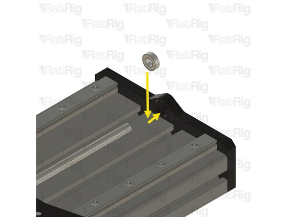
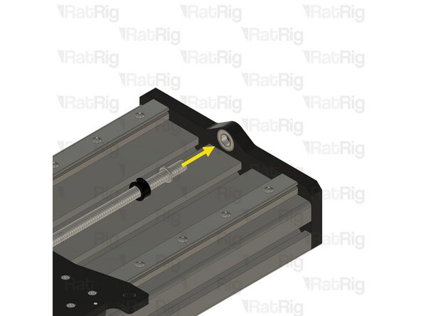
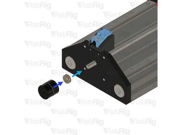
688ZZ Ball bearing
-
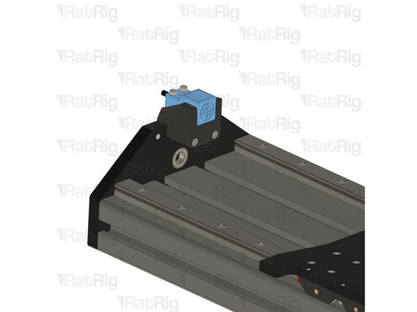
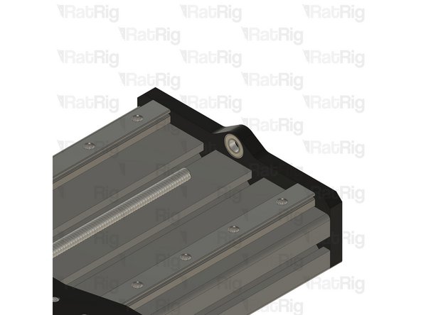
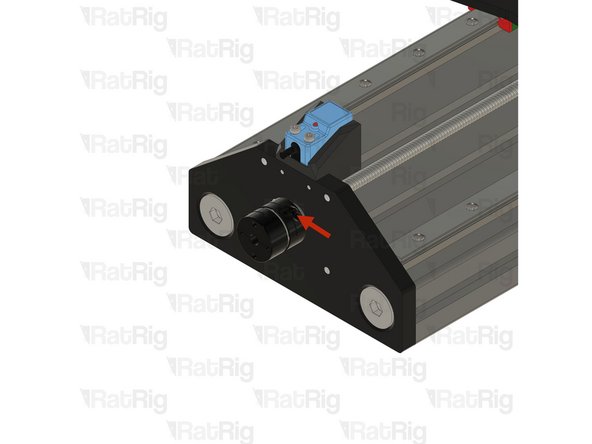
Push the ball bearing against the inner side of the plate, ensuring it stays inside the designated groove.
-
Push the Lead Screw through the hole in the ball bearing
-
-
-
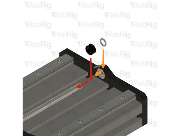
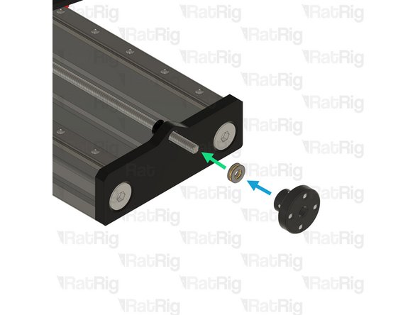
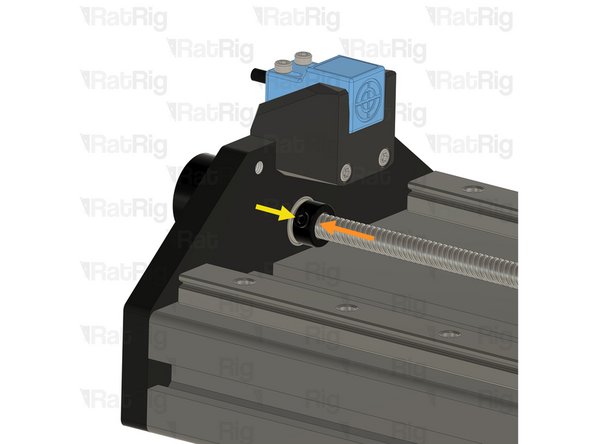
Precision Shim 12x8x1mm
-
Slide the Precision Shim on to the Lead Screw
-
Lock Collar
-
Slide the Lock Collar on to the Lead Screw
-
Insert the lead screw until it reaches the Y joiner plate.
-
Screw the Lead Screw through both Nut Blocks under the Y joiner plate.
-
-
-
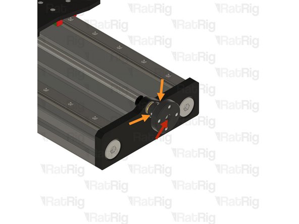
While threading the lead screw, ensure that it moves smoothly. It should thread effortlessly while the second POM block remains loose.
-
Gently tighten the screws on the second POM block while rotating the lead screw by hand. Monitor the resistance carefully—as soon as you feel any increase in resistance, stop tightening. Avoid over-tightening, as this could introduce unnecessary drag to the system.
-
Gently pull and push the lead screw along its axis to check for backlash. There should be no play when performing this movement. If you detect any play, tighten the screws slightly and test again. Repeat this process until the play is fully eliminated, ensuring a secure fit without introducing excessive resistance.
-
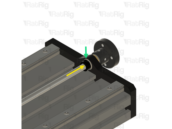
688ZZ Ball bearing - Push the ball bearing against the inner side of the plate, ensuring it stays inside the designated groove.
-
-
-
Lock Collar
-
Slide the Lock Collar on to the Lead Screw
-
Precision Shim 12x8x1mm
-
Slide the Precision Shim on to the Lead Screw
-
Insert the lead screw until it reaches the Rat Rig Mill - 4160 Bearing end plate.
-
Thrust Bearing F8-16M
-
Jog wheel
-
Install the thrust Bearing and Jog wheel on to the exposed end of the Lead Screw as shown
-
-
-
Ensure the lead screw surface is roughly 1-2mm inside the jog wheel
-
After positioning the jog wheel, tighten the two set screws to secure it in place.
-
Pull the X joiner plate away from the jog wheel, as to ensure the jog wheel and thrust bearing sit tight against the front Y plate.
-
Excessive force is unnecessary, as it may cause the lead screw to bind.
-
Push the lock collar against the Y front plate.
-
Tighten the set screw on the lock collar to secure it in place.
-
Install the Thrust Bearing on to the exposed end of the Lead Screw as shown
-
Install the Coupler - Disk Type on to the exposed end of the Lead Screw as shown
-
-
-
Gently push the coupler against the Thrust Bearing and tighten the set screw.
-
Push the lock collar against the Y rear plate
-
Tighten the set screw on the lock collar to secure it in place
-
Rotate the coupler to verify that the lead screw moves smoothly and the Y joiner plate operates as expected
-
-
-
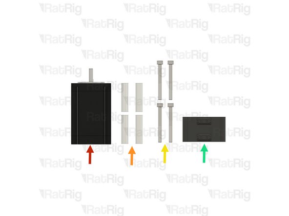
Nema 23 Stepper Motor High Torque
-
4x 40mm Aluminium Spacer
-
4x M5x50 Cap Head Screw
-
mill_stepper_cable_management printed part
-
-
-
4x 40mm Aluminium Spacer
-
Nema 23 Stepper Motor High Torque
-
4x M5x50 Cap Head Screw
-
Assemble the components above as shown.
-
Tighten the set screw on the coupler, to secure the stepper motor shaft to it.
-
Insert the mill_stepper_cable_management printed part as shown.
-
-
-
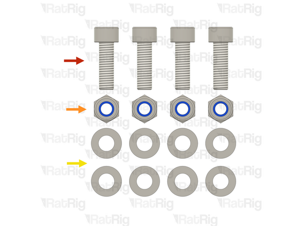
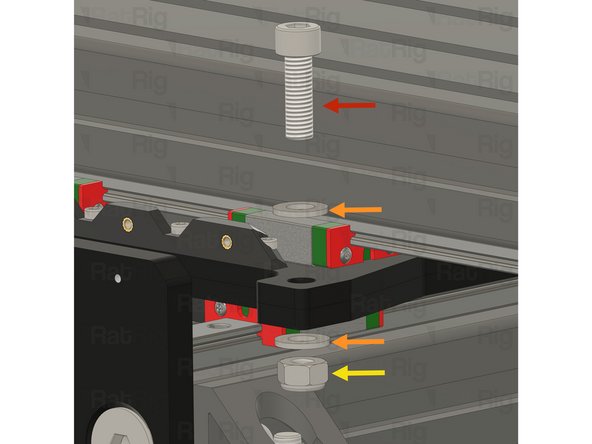
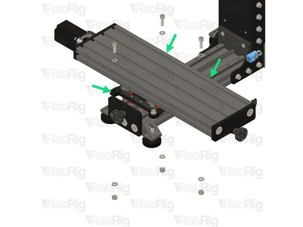
4x M8x25 Cap Head Screw
-
4x M8 Nylon Locking Hex Nut
-
8x M8 Washer
-
-
-
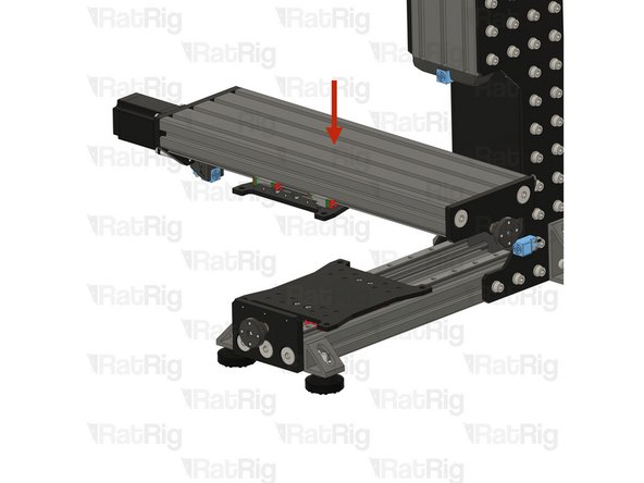
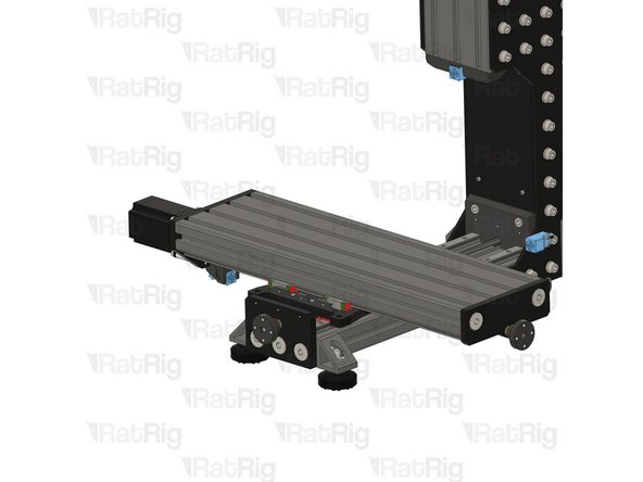
Carefully place the X axis on the Mill, aligning the X and Y joiner plates as shown.
-
-
-
M8x25 Cap Head Screw
-
2x M8 Washer
-
M8 Nylon Locking Hex Nut
-
Assemble the components as shown.
-
Repeat for the other three joiner plate holes.
-
-
-
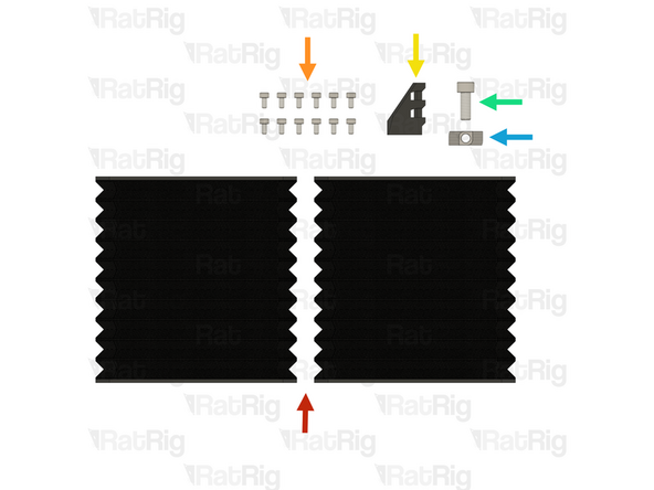
Rat Rig Mill - Bellow 11 Link
-
6x M3x6 Cap Head Screw
-
mill_x_umbilical_mount
-
M6x16 Cap Head Screw
-
M6 4040 Drop in T-nuts
-
-
-
Rat Rig Mill - Bellow 11 Link
-
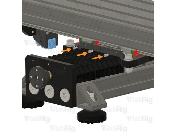
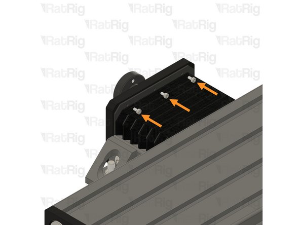
M3x6 Cap Head Screw
-
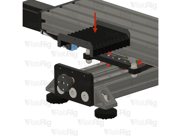
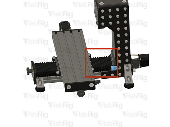
Place the bellow on the designated location and secure it using 3x M3x6 Cap Head Screws on each end.
-
-
-
Repeat The previous Step and install the rear bellow cover.
-
-
-
mill_x_umbilical_mount
-
M6x16 Cap Head Screw
-
M6 4040 Drop in T-nuts
-
Assemble the parts as shown.
-