Introduction
BEFORE STARTING:
Before beginning this guide, you must prepare all the necessary wires for the assembly. Below is a list of the required wires. The following nomenclature will be used: (Wire Length)_(AWG)_(Wire Color)_(A-End Connector)_(B-End Connector)_(ID number).
Use a small piece of tape to label each wire to ensure a smooth assembly process.
ALL AC WIRES ARE STILL BEING POLISHED (AVAILABLE BY THE END OF MARCH)
- 700mm - 16AWG RED (A-Ferrule, B-Ferrule) (4)
- 700mm - 16AWG BLACK (A-Ferrule, B-Fork) (5)
- 120mm - 16AWG RED (A-Fork, B-Fork) (6)
- 600mm - 16AWG RED (A-Fork, B-Ferrule) (7)
- 600mm - 16AWG BLACK (A-Fork, B-Ferrule) (8)
- 150mm - 22AWG BLACK (A-Fork, B-Ferrule) (9)
- 150mm - 22AWG RED (A-Ferrule, B-Ferrule) (10)
- 150mm - 22AWG BLACK (A-Ferrule, B-Ferrule) (11)
- 500mm - 22AWG RED (A-Ferrule, B-Fork) (12)
- 2x 500mm - 22AWG BLACK (A-Ferrule, B-Fork) (13)
- 4x 550mm - Multicore 3 Conductor - 24AWG BLACK (A-(3x)Ferrule, B-(3x)Ferrule) (14)
- 4x 800mm - 16AWG RED (A-Fork, B-Ferrule) (15)
- 4x 800mm - 16AWG BLACK (A-Fork, B-Ferrule) (16)
- 4x 30mm - 22AWG BLACK (A-Ferrule, B-Ferrule) (17)
- 3x 100mm - 22AWG RED (A-Ferrule, B-Ferrule) (18)
- 900mm - Multicore 2 Conductor - 24AWG (A-2xFerrule, B-2xFerrule) (19)
- 100mm - 16AWG BLACK (A-Ferrule, B-Ferrule) (20)
-
-
The DM542T stepper drivers allow current and micro-stepping control, resulting in a vast range of configurations.
-
Adjust the switches on the drivers for each stepper motor
-
Depressing switches 1 and 2 while simultaneously elevating switch 3 establishes a current of 2.69 amperes, marginally below the rated current for the stepper motors. This configuration is designed to enhance performance and extend the operational lifespan of the components.
-
The upwwards positioning of switch 4 ensures that only half of the designated current is provided to the stepper motors when they are at a standstill, thus preventing the potential for overheating in both the stepper motors and the associated drivers.
-
STRONGHOLD PRO Elevating Switches 5 and 6 with the downward orientation of Switches 7 and 8 configures the pulse/revolution rate to 1600, in conjunction with the ball screws, this specific arrangement ensures that the axis traverses a distance of 1mm for each full revolution accomplished by the stepper motor, with the exception of the Z axis.
-
Repeat for the other DM542T stepper drivers
-
-
-
There is a small switch on top of the DM542T stepper driver, ensure it is set to 5V as the AXBB signal is 5V.
-
Repeat for the other DM542T stepper drivers
-
-
-
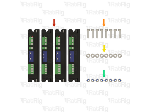
4x Stepper driver - OMC DM542T
-
8x M4x16 cap head screw
-
8x M4 washer
-
8x M4 locking hex nut
-
-
-
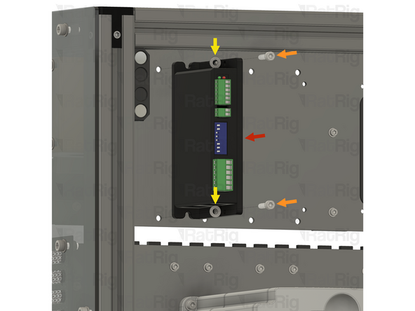
1x Stepper driver - OMC DM542T
-
2x M4x16 cap head screw
-
2x M4 washer
-
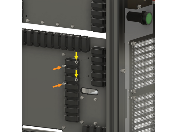
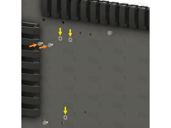
Install an M4 washer on to each M4x16 screw
-
Align the stepper driver with the holes on the panel, and insert an M4x16 screw through the stepper driver and panel as shown
-
Keep supporting the stepper driver until the locking hex nuts are installed in the next step
-
-
-
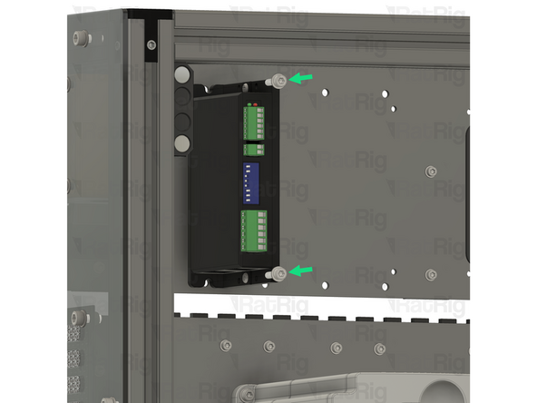
2x M4 locking hex nut
-
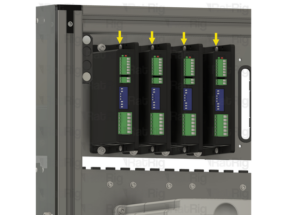
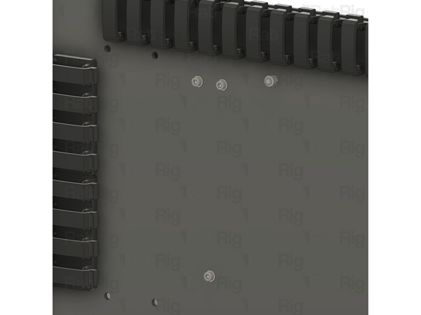
Install an M4 locking hex nut on to each of the M4x16 screws and tighten them to secure the stepper driver to the panel
-
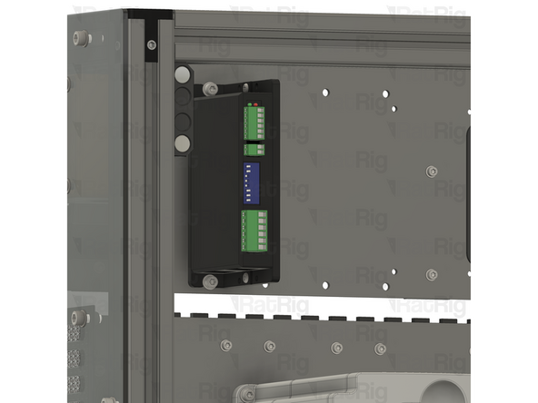
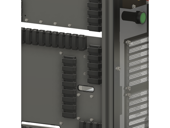
Repeat the previous step, and this step, to install the remaining 3 stepper drivers as shown
-
-
-
1x CNCDrive AXBB-E CNC controller
-
4x Spacer - Nylon - 4.2x6.3x10mm
-
4x M4x25 cap head screw
-
4x M4 locking hex nut
-
-
-
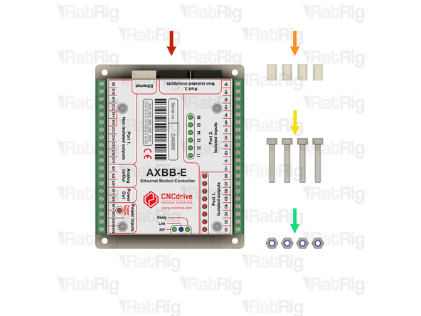
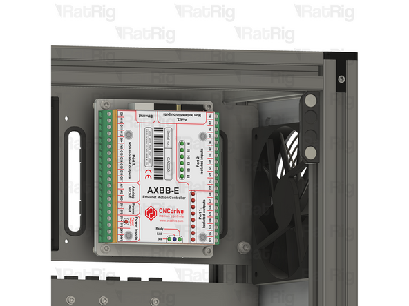
1x CNCDrive AXBB-E CNC controller
-
4x Spacer - Nylon - 4.2x6.3x10mm
-
4x M4x25 cap head screw
-
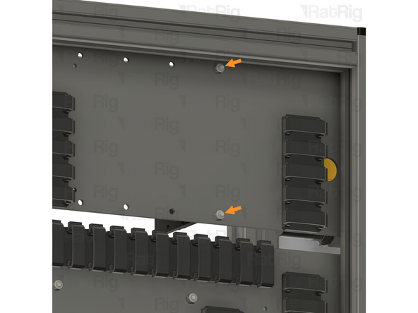
Install an M4x25 screw through each mounting hole on the AXBB-E CNC controller
-
Install a nylon spacer on to each M4x25 screw
-
Align the M4x25 screws with the holes in the panel as shown
-
Keep supporting the AXBB-E CNC controller until the locking hex nuts are installed in the next step
-
-
-
4x M4 locking hex nut
-
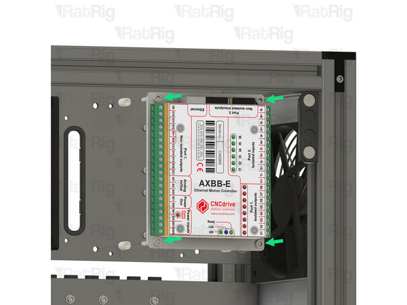
Install an M4 locking hex nut on to each of the M4x25 screws and tighten them to secure the AXBB-E CNC controller to the panel
-
-
-
5x M3x6 cap head screw
-
5x M3 washer
-
1x Meanwell RS-15-5 5V power supply
-
1x Meanwell RSP-75-24 24V power supply
-
-
-
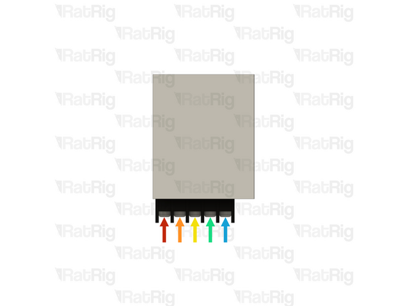
It is recommended to wire the power supply before installing it in the electronics enclosure. Please connect the following wires:
-
600mm - 18AWG BROWN (A-Fork, B-Ferrule) (21)
-
600mm - 18AWG BLUE (A-Fork, B-Ferrule) (22)
-
600mm - 18AWG YELLOW/GREEN (A-Fork, B-Ferrule) (23)
-
2x 400mm - 22AWG BLACK (A-Ferrule, B-Fork) (13) Overlay the two forks in the screw terminal.
-
400mm - 22AWG RED (A-Ferrule, B-Fork) (12)
-
Connect all the wires above to the power supply, using the fork connectors on each wire
-
After insertion, attempt to pull the wire to verify that it is securely attached
-
-
-
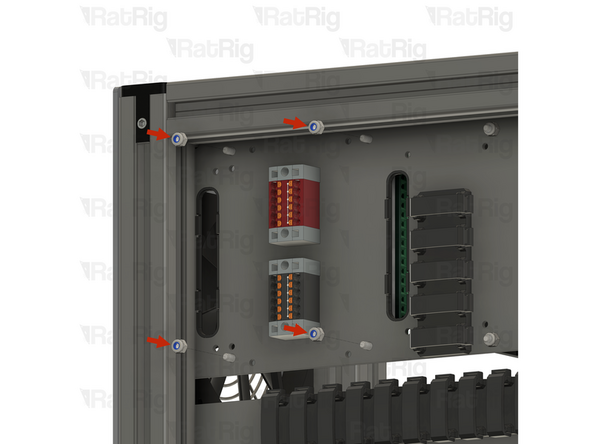
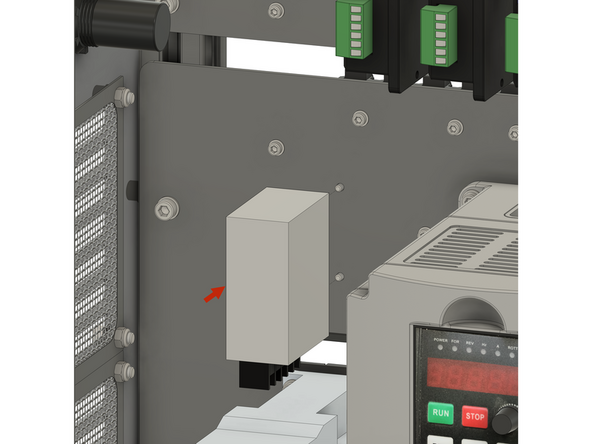
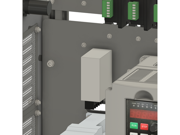
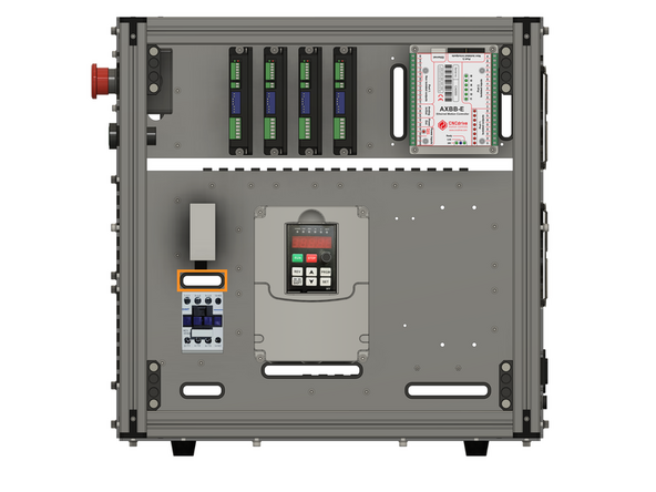
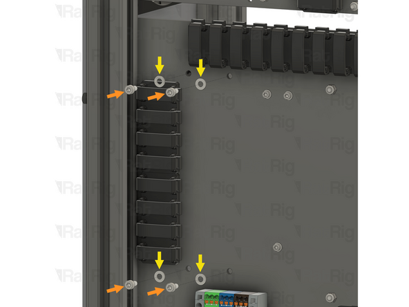
Install the component using the designated holes
-
2x M3x6 cap head screw
-
2x M3 washer
-
Install an M3 washer on to each M3x6 screw and insert them into the marked holes
-
-
-
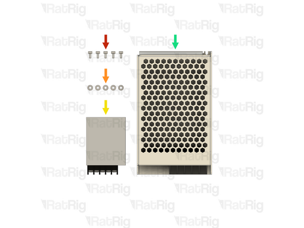
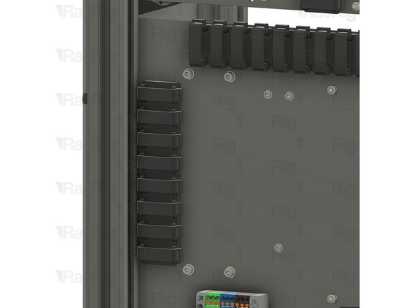
1x Meanwell RS-15-5 5V power supply
-
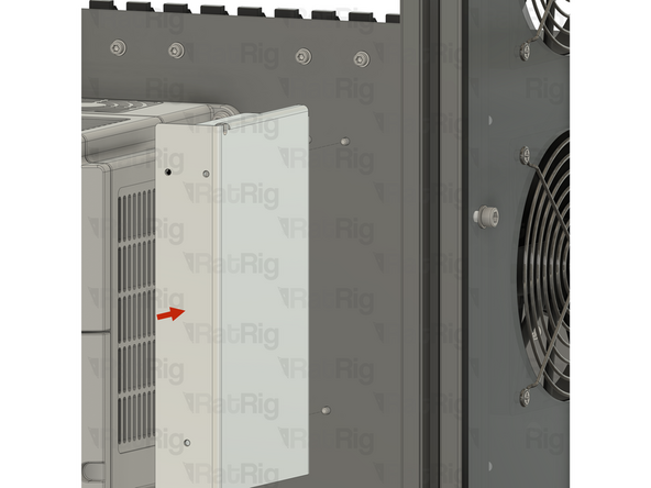
Install the power supply as shown, securing it by screwing the M3x6 screws into the threaded holes on the side of the PSU body
-
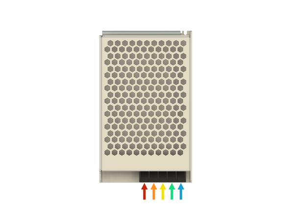
Feed all of the power supply wires through the designated slot
-
-
-
It is recommended to wire the power supply before installing it in the electronics enclosure. Please connect the following wires:
-
600mm - 16AWG RED (A-Fork, B-Ferrule) (7)
-
600mm - 22AWG BLACK (A-Fork, B-Ferrule) (8)
-
200mm - 18AWG YELLOW/GREEN (A-Fork, B-Ferrule) (24)
-
200mm - 18AWG BLUE (A-Fork, B-Ferrule) (25)
-
200mm - 18AWG BROWN (A-Fork, B-Ferrule) (26)
-
Connect all the wires above to the power supply, using the fork connectors on each wire
-
After insertion, attempt to pull the wire to verify that it is securely attached
-
-
-
Install the component using the designated holes
-
3x M3x6 cap head screw
-
3x M3 washer
-
Install an M3 washer on to each M3x6 screw and insert them into the marked holes
-
-
-
1x Meanwell RSP-75-24 24V power supply
-
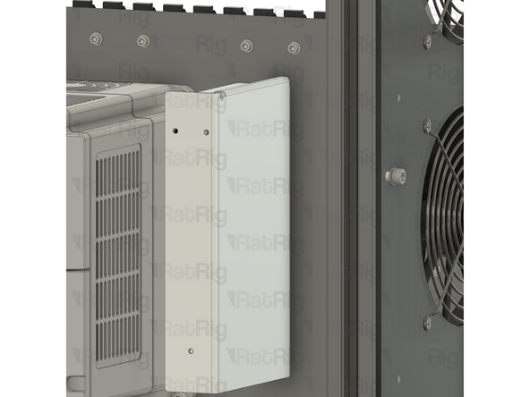
Install the power supply as shown, securing it by screwing the M3x6 screws into the threaded holes on the side of the PSU body
-
Feed all of the power supply wires through the designated slot
-
-
-
2x Meanwell RSP-320-48 48V power supply
-
4x M4x8 cap head screw
-
4x M4 washer
-
-
-
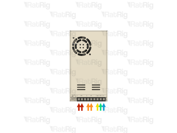
It is recommended to wire the power supply before installing it in the electronics enclosure. Please connect the following wires:
-
2x 800mm - 16AWG RED (A-Fork, B-Ferrule) (15)
-
2x 800mm - 16AWG BLACK (A-Fork, B-Ferrule) (16)
-
250mm - 18AWG YELLOW/GREEN (A-Fork, B-Ferrule) (37)
-
700mm - 18AWG BLUE (A-Fork, B-Ferrule) (36)
-
700mm - 18AWG BROWN (A-Fork, B-Ferrule) (35)
-
Connect all the wires above to the power supply, using the fork connectors on each wire
-
After insertion, attempt to pull the wire to verify that it is securely attached
-
-
-
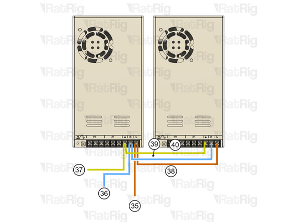
It is recommended to wire the power supply before installing it in the electronics enclosure. Please connect the following wires:
-
2x 800mm - 16AWG RED (A-Fork, B-Ferrule) (15)
-
2x 800mm - 16AWG BLACK (A-Fork, B-Ferrule) (16)
-
130mm - 18AWG BROWN (A-Fork, B-Fork) (38)
-
130mm - 18AWG BLUE (A-Fork, B-Fork) (39)
-
130mm - 18AWG YELLOWGREEN (A-Fork, B-Fork) (40)
-
Wires 38, 39, and 40 must be installed in the same screw terminals as wires 41, 36, and 35, as indicated in the diagram for the first 48V power supply, which was prepared in the previous step.
-
-
-
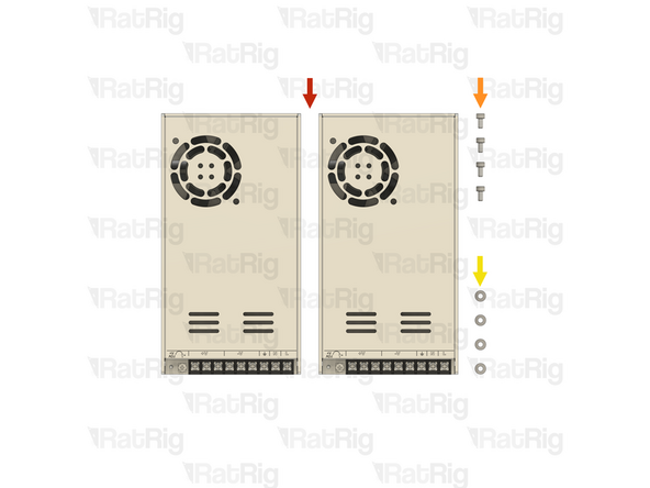
Install the component using the designated holes
-
4x M4x8 cap head screw
-
4x M4 washer
-
Install an M4 washer on to each M4x8 screw and insert them into the marked holes
-
-
-
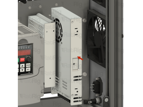
2x Meanwell RSP-320-48 48V power supply
-
Install the power supply as shown, securing it by screwing the M4x8 screws into the threaded holes on the side of the PSU body
-
Repeat to install the second power supply, paying attention to the orientation
-
Feed all of the wires from both power supplies through the designated slot
-
-
-
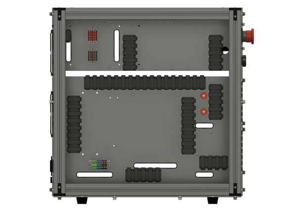
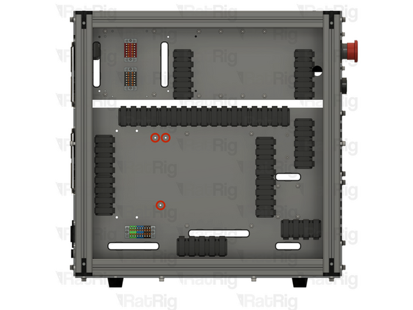
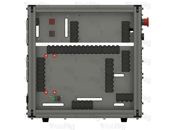
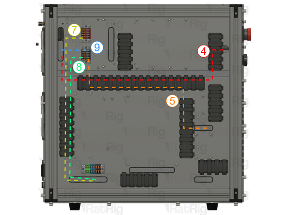
Route the wires on the back of the enclosure as shown.
-
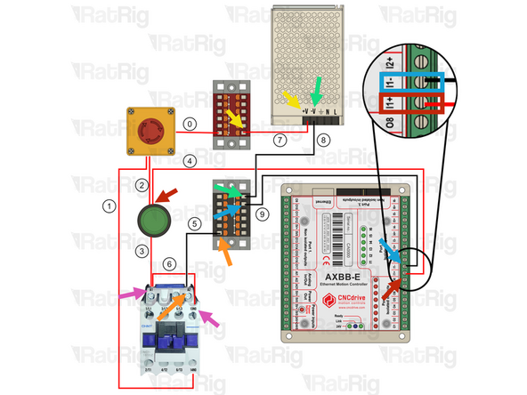
700mm - 16AWG RED (A-Ferrule, B-Ferrule) (4) Connect the wire from the start button (in) to the I1+ terminal on port2 of the AXBB-E
-
700mm - 16AWG BLACK (A-Ferrule, B-Fork) (5) Connect the ferrule in the Black PTFix block and the fork on the A2 terminal of the contactor.
-
600mm - 16AWG RED (A-Fork, B-Ferrule) (7) Connect the ferrule into the Red PTFix block, the fork end should have been connected to the power supply here.
-
600mm - 16AWG BLACK (A-Fork, B-Ferrule) (8) Connect the ferrule into the Black PTFix block, the fork end should have been connected to the power supply here.
-
150mm - 22AWG BLACK (A-Fork, B-Ferrule) (9) Connect one end of the wire to the Black PTFix block and the other to the I1- terminal on port 2 of the AXBB-E
-
120mm - 16AWG RED (A-Fork, B-Fork) (6) Connect the wire from terminal 13NO on hte contactor to the A1 terminal on the contactor. A1 should have 2 Forks inserted.
-
-
-
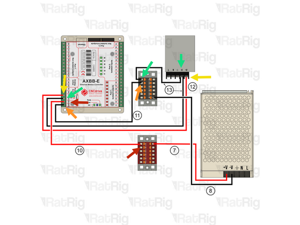
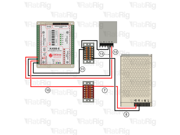
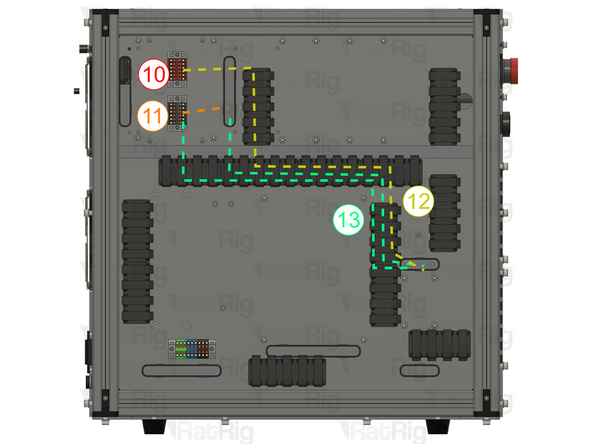
Route the wires on the back of the enclosure as shown.
-
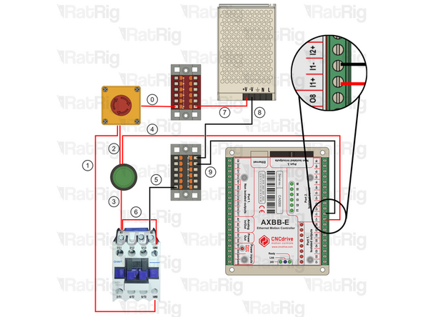
150mm - 22AWG RED (A-Ferrule, B-Ferrule) (10) Connect the wire from the Red PTFix block to the +24V input on the AXBB-E
-
150mm - 22AWG BLACK (A-Ferrule, B-Ferrule) (11) Connect the wire from the Black PTFix block to the -24V input on the AXBB-E
-
500mm - 22AWG RED (A-Ferrule, B-Fork) (12) Connect the fork end to the +V terminal on the 5V power supply and the ferrule end in the 5V+ terminal on the AXBB-E.
-
2x 500mm - 22AWG BLACK (A-Ferrule, B-Fork) (13) Connect the wire from the -V terminal on the 5V Power supply using the fork connector and connect the ferrule in the Black PTFix block. The second (13) wire should be connected from the -V terminal on the 5V Power supply using the fork connector and then connected to the AXBB-E 5V0 terminal
-
-
-
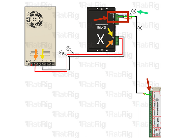
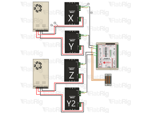
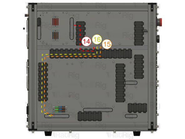
Ignore Y2 if you are wiring a Rat Rig Mill. Repeat the Steps to connect all drivers.
-
4x 550mm - Multicore 3 Conductor - 24AWG BLACK (A-(3x)Ferrule, B-(3x)Ferrule) (14)
-
DRIVER SIDE: Connect the white wire to PUL+ , the green wire to DIR+ and the brown wire to DIR-
-
AXBB-E Side: Connect the white wire to 09 , the green wire to 010 and the brown wire to the Black PTFix Block
-
Follow the order and connect stepper Y( PUL+ to 011, DIR+ to 012), then Z( PUL+ to 013, DIR+ to 014), Lastly Y2( PUL+ to 015, DIR+ to 016)
-
4x 30mm - 22AWG BLACK (A-Ferrule, B-Ferrule) (17) To jump DIR- with PUL-
-
4x 800mm - 16AWG RED (A-Fork, B-Ferrule) (15) The Fork terminals should be already wired to the 48V Power supplies here. Then connect it to +VDC on the driver.
-
4x 800mm - 16AWG BLACK (A-Fork, B-Ferrule) (16) The Fork terminals should be already wired to the 48V Power supplies here. Then connect it to GND on the driver.
-
-
-
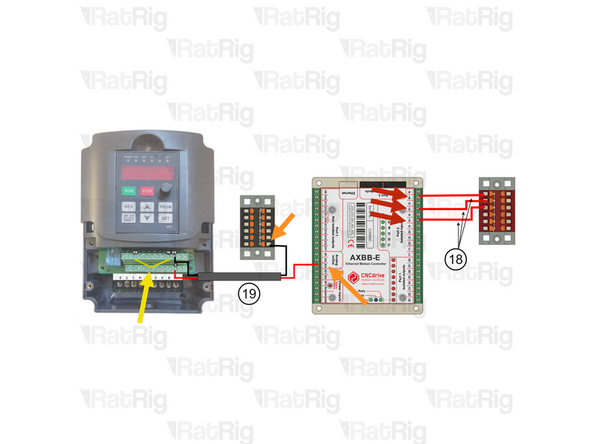
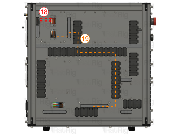
3x 100mm - 22AWG RED (A-Ferrule, B-Ferrule) (18) Connect one end to the Red PTFix block and the other to I6+ terminal on port 2 of the AXBB-E.
-
Repeat the previous Step and connect I5+ and I4+ the the Red PTFix Block.
-
900mm - Multicore 2 Conductor - 24AWG (A-2xFerrule, B-2xFerrule) (19) Connect the 2 wire cable to from the VFD and AXBB-E
-
Use the Red wire for the VI terminal on the VFD and A01 analog input on the AXBB-E
-
Use the Black wire for the black PTFix Block and ACM terminal on the VFD.
-
100mm - 16AWG BLACK (A-Ferrule, B-Ferrule) (20) Connect the FOR terminal with the DCM terminal on the VFD
-
-
-
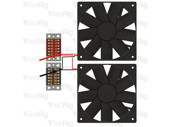
Cut the JST connectors on the cooling fans and crimp both red wires in the same ferrule, then insert it into the Red PTFix Block.
-
Cut the JST connectors on the cooling fans and crimp both black wires in the same ferrule, then insert it into the Black PTFix Block.
-