-
-
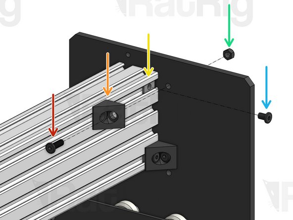
Low Profile Screw M5x15mm
-
X-Gantry C-Beam profile
-
X-Gantry 2040 profile (Tapped)
-
-
-
T-Nut M5. Note that the flat face is facing outwards.
-
Low Profile Screw M5x15mm
-
Recheck the bottom Eccentric Spacers on the X-Carriage-Assembly to make sure they are touching the rail, there is no wobble, and that the X-Carriage-Assembly runs smoothly along the whole length of the C-Beam.
-
Place the X-Gantry Assembly onto a flat table. Check if both Y-Plates are sitting flush with the table. Loosen the extrusions and adjust if needed.
-
-
-
Repeat this step on both sides of the C-Beam.
-
Low Profile Screw M5x15mm
-
90º Angle Corner Connector
-
T-Nut M5 (inserted inside the slot on step 2)
-
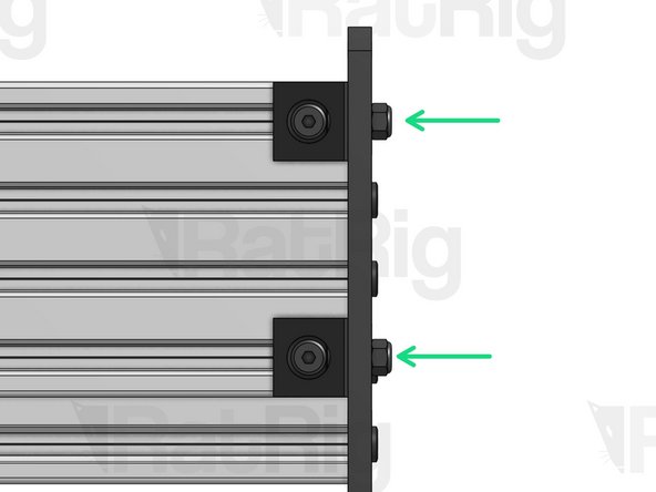
Hex Locking Nut M5
-
Low Profile Screw M5x8mm
-
-
-
X Lead Screw
-
Thrust Bearing
-
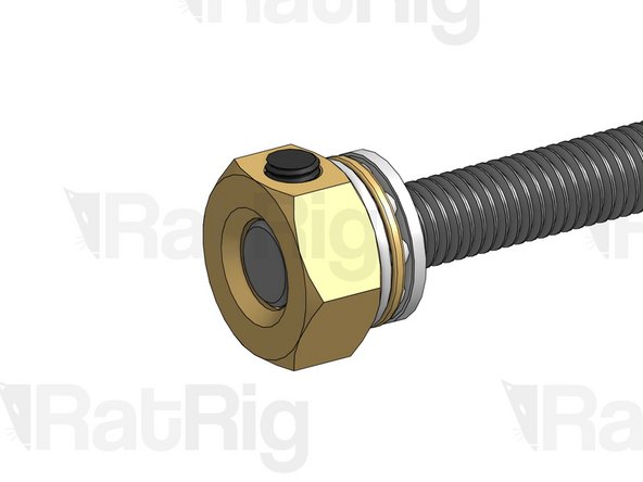
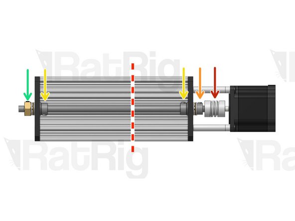
Tensioner Nut. For now, screw it in just a tiny bit, so it holds its position.
-
Set Screw - set in position, but don't tighten down yet.
-
-
-
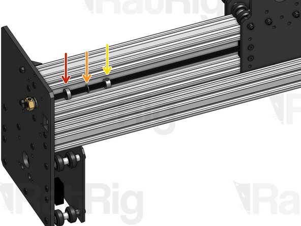
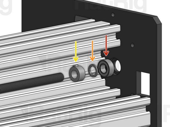
Insert the X Lead Screw through the Left Y-Plate hole. Right after the hole, insert the 3 parts below in order.
-
688ZZ Ball Bearing
-
Precision Shim 12x8x1mm
-
Lock Collar 8mm. Set in position, but don't tighten down yet.
-
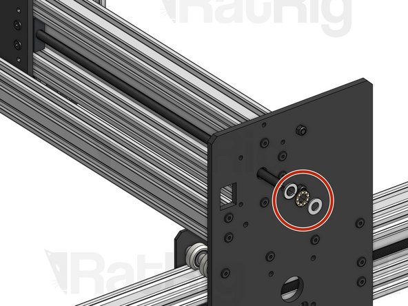
Fasten your lead screw through the nut blocks on the X-Plate. Before the lead screw starts coming out through the Right Y-Plate, insert the 3 parts again, in reverse order this time.
-
-
-
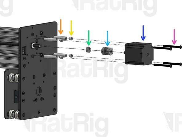
Thrust Bearing
-
Aluminium Spacer 40mm
-
Aluminium Spacer 6mm
-
Lock Collar 8mm. Set in position, don't tighten yet.
-
Flexible Coupling - 1/4" x 8mm. Set in position, don't tighten yet.
-
Nema 23 Motor
-
Low Profile Screw M5x55mm
-
-
-
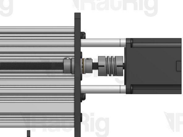
Start by adjusting the position of the Flexible Coupling to make sure that both the Lead Screw and the Nema 23 motor shaft are fully inserted inside the ends of the coupling.
-
Make sure the flat face of the D shaped motor shaft is facing the set screw on the Flexible Coupling. Tighten down the set screws on both sides.
-
Tighten down the larger clamping screws on your coupling.
-
Press the lock collar against the Y plate and firmly tighten down its set screw.
-
Grab your XZ Carriage firmly, so it doesn't move, and use a spanner to tighten the Tensioner nut until your lead screw is under tension. Excessive tension should be avoided, as it will increase part wear. You may need to adjust tension once you start using the machine, if you notice whip/vibration on the lead screw.
-
Instead of grabbing the carriage, you can also manually spin the lead screw until the carriage has reached its right-most position. In this position the carriage can't move once you start tightening the Tensioner Nut.
-
Press these 2 lock collars against their respective Y Plates and tighten down their set screws.
-
Almost done!
Finish Line


