
-
-
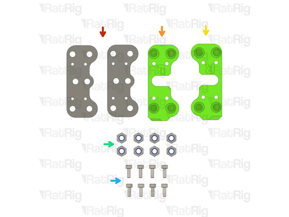
2x vc4_xy_joiner_upper plate
-
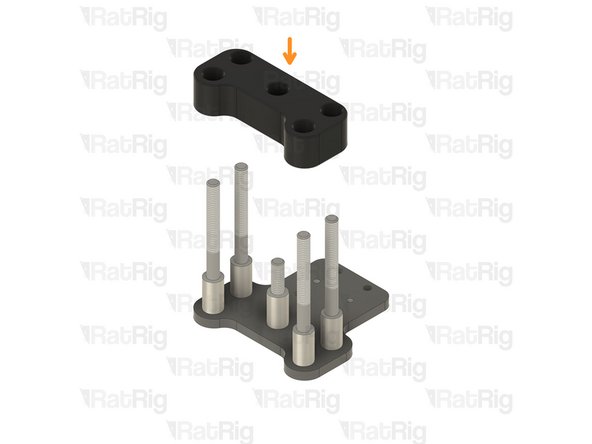
2x vc4_x_endstop printed part
-
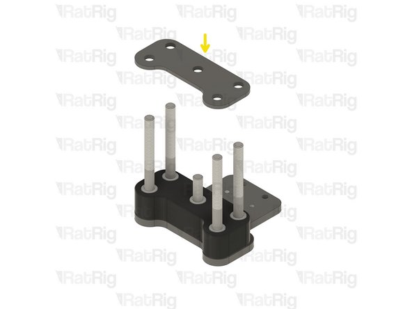
2x vc4_xy_joiner_middle plate
-
8x M5x60 Countersink Screw
-
2x Low Profile Screw 30mm
-
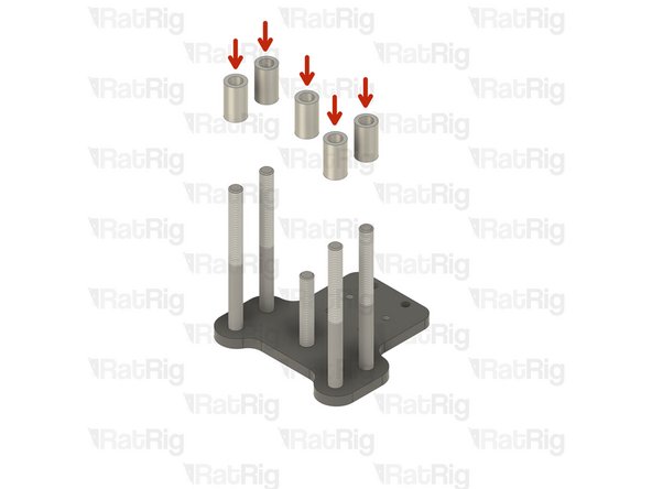
14x Aluminium Spacer 5x8x14mm
-
-
-
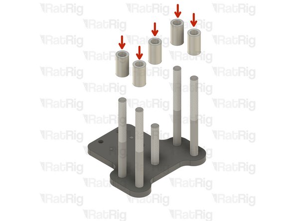
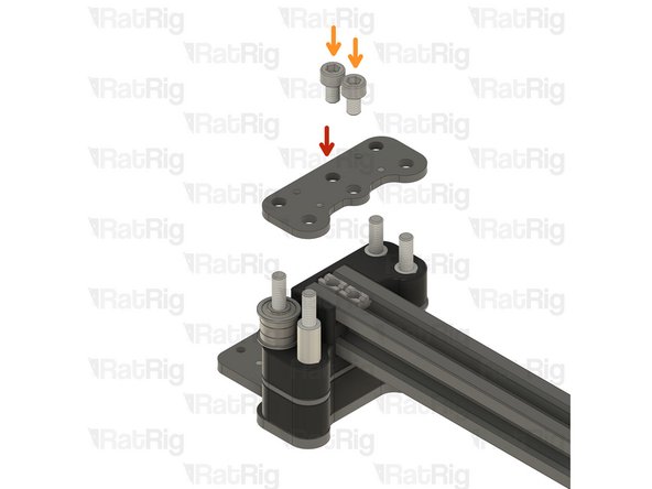
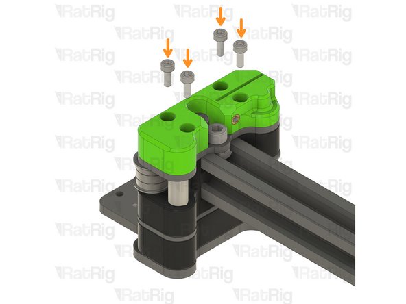
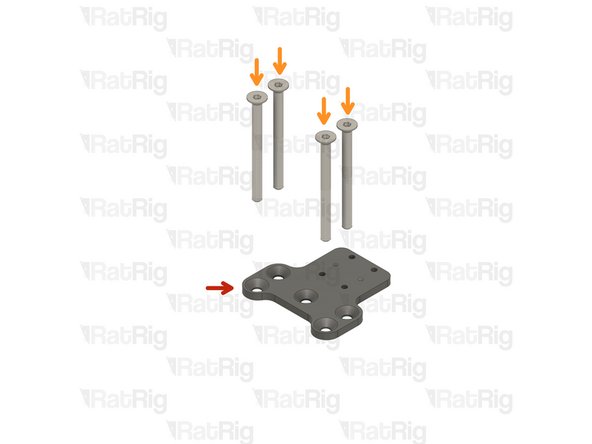
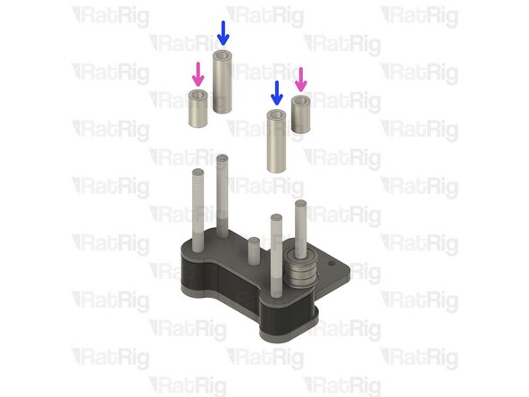
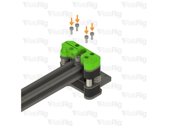
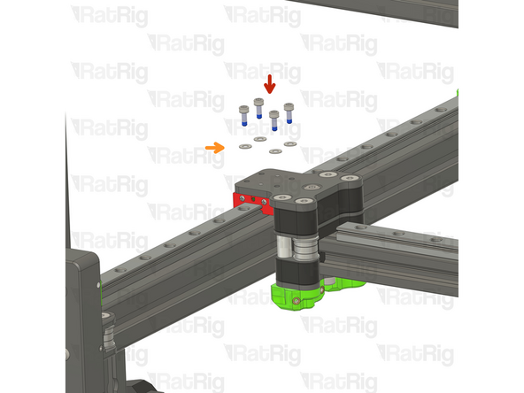
vc4_xy_joiner_upper plate
-
M5x60 Countersink Screw
-
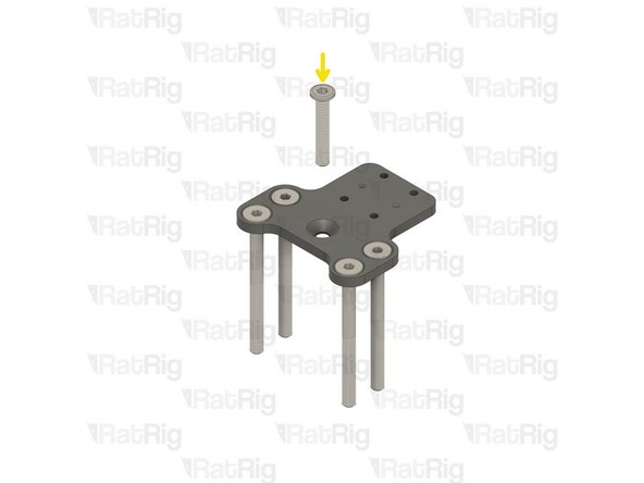
M5x30 Low Profile Screw
-
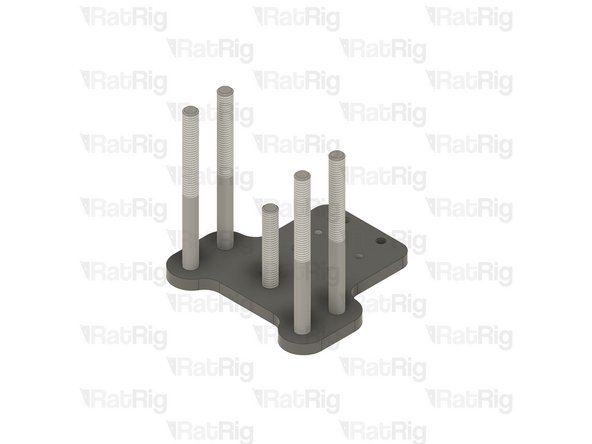
Insert the screws on the plate and flip the assembly upside down as shown.
-
-
-
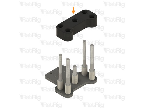
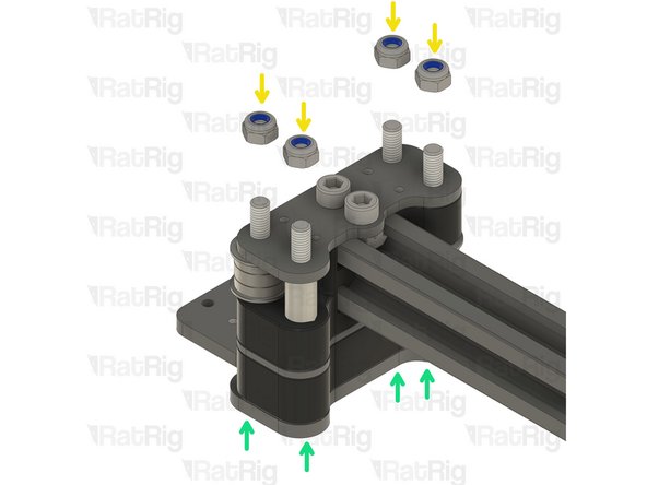
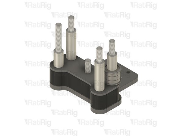
Aluminium Spacer 5x8x14mm
-
Insert one Aluminium spacer on each screw
-
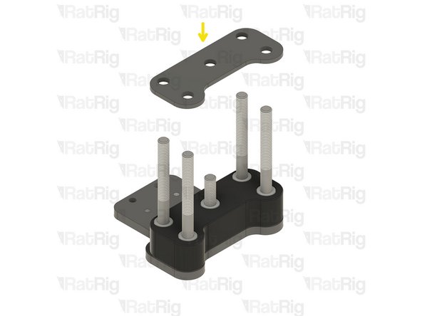
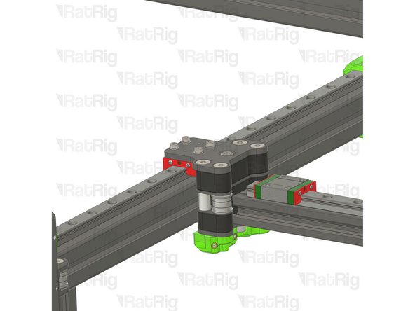
vc4_x_endstop printed part
-
Align the printed part and insert it through the aluminium spacers.
-
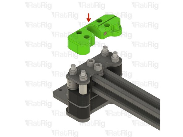
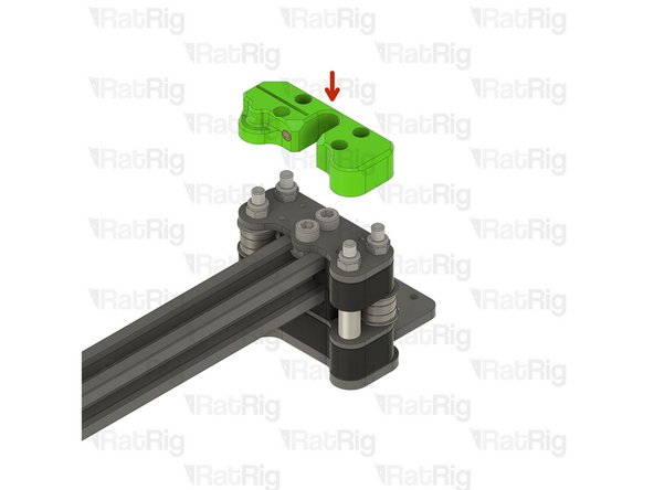
vc4_xy_joiner_middle plate
-
Align the plate and insert it through the screws.
-
-
-
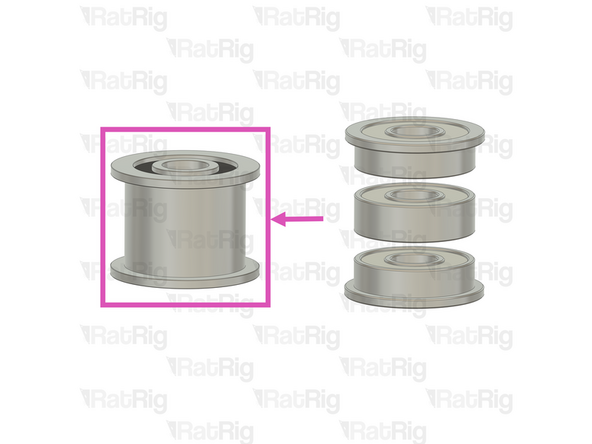
2x vc4_xy_spacer
-
4x Ball Bearing 695ZZ
-
8x Ball Bearing F695ZZ
-
4x Mini Precision Shim 8x5x1mm
-
4x Aluminium Spacer 5x8x27mm
-
4x Heavy-Duty Idler – The latest V-Core 4 kits now feature these heavy-duty idlers as a replacement for the previously used bearing stack assemblies.
-
-
-
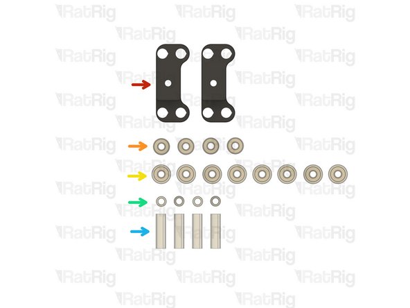
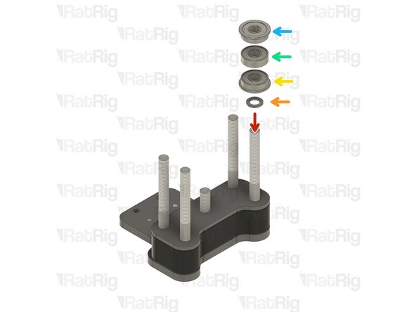
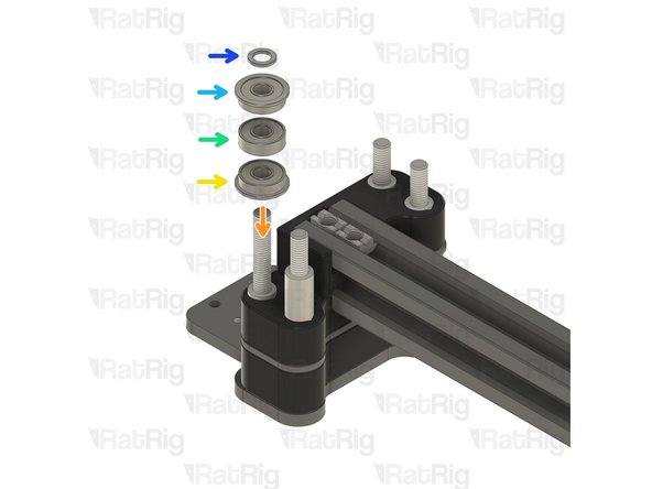
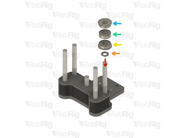
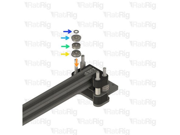
Install the following components in the order shown in the image:
-
Mini Precision Shim
-
F695ZZ Ball Bearing (Flange at the bottom)
-
695ZZ Ball Bearing
-
F695ZZ Ball Bearing (Flange at the top)
-
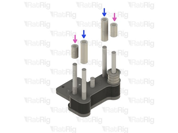
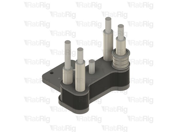
Aluminium Spacer 5x8x27mm
-
Aluminium Spacer 5x8x14mm
-
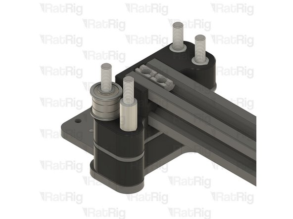
Insert the aluminium spacers on the designated screws.
-
-
-
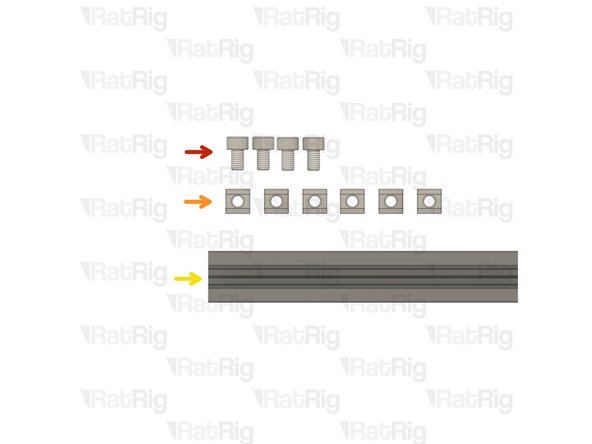
4x M5x8 Cap Head Screw
-
6x T-Nut M5 Square type for 2020
-
V-Slot 2020 - 525mm
-
-
-
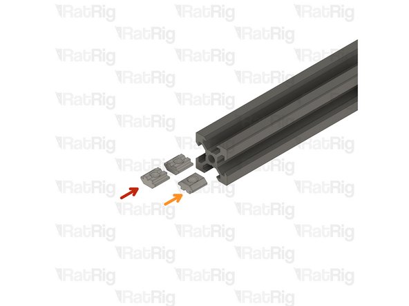
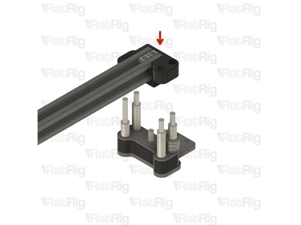
Insert two T-Nut Square type for 2020 on the top slot.
-
Insert one T-Nut Square type for 2020 on the lower slot.
-
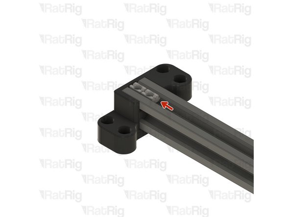
Gently insert the V-Slot 2020 extrusion inside the vc4_xy_spacer. The two square T-nuts must be facing the opening on the printed part, as shown.
-
Ensure the extrusion and the printed part are flush.
-
-
-
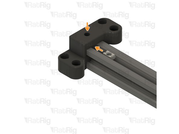
Push the two T-Nut Square type to the end of the assembly
-
Flip the gantry upside down and push the single T-Nut Square type underneath the printed part, ensuring it is aligned with the hole on the printed part.
-
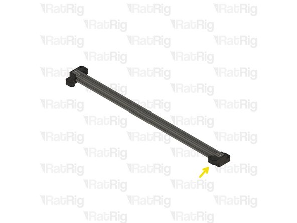
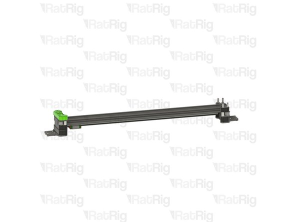
Repeat Steps 7 and 8 and prepare the other end of the assembly.
-
-
-
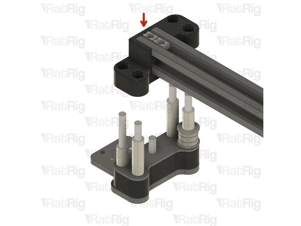
Take the assembly from the previous Step and insert the printed part holes in the aluminium spaces of the left joiner from Step 5
-
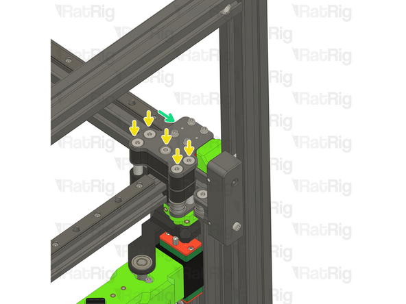
Install the following components in the order shown in the image:
-
F695ZZ Ball Bearing (Flange at the bottom)
-
695ZZ Ball Bearing
-
F695ZZ Ball Bearing (Flange at the top)
-
Mini Precision Shim
-
-
-
2x vc4_xy_joiner_lower plate
-
vc4_xy_trim_left printed part
-
vc4_xy_trim_right printed part
-
8x M5 Hex Locking nut
-
8x M3x8 Cap Head Screw
-
-
-
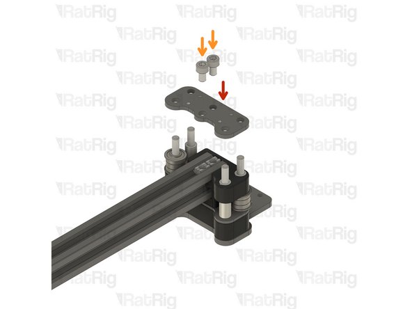
vc4_xy_joiner_lower plate
-
2x M5x8 Cap Head Screw
-
Insert the screws through the plate, and tighten them to the t-nuts on the 2020 extrusion.
-
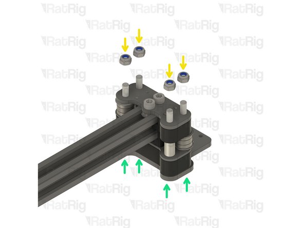
M5 Hex Locking nut
-
Thread a M5 hex locking nut in each screw
-
Tighten the screws in each of M5 hex locking nuts were inserted
-
Do not overtighten the screws as too much force can cause the gantry to bind when installed on the V-Core 4.
-
-
-
vc4_xy_trim_left printed part
-
4x M3x8 Cap Head Screw
-
Insert the screws through the printed part and tighten them to the plate
-
-
-
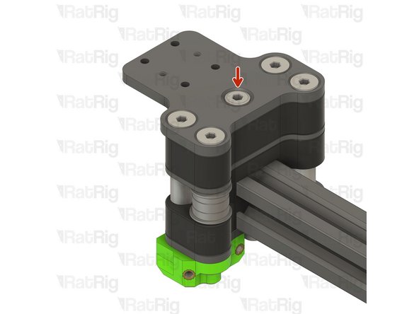
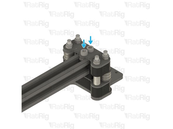
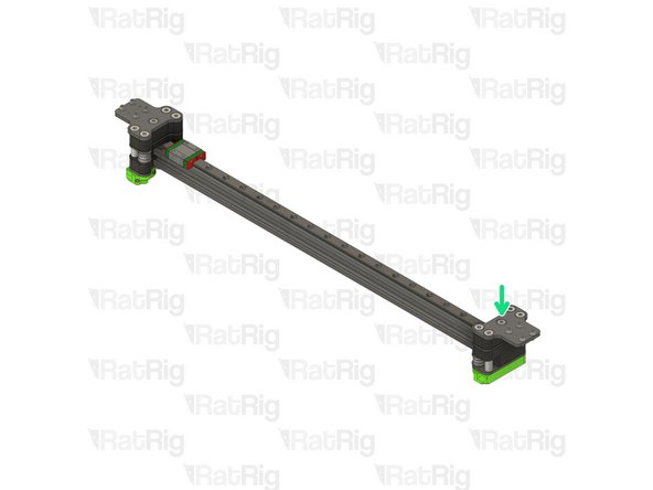
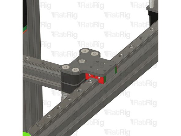
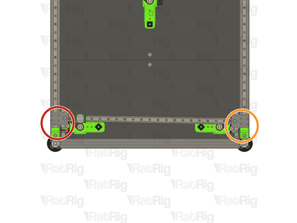
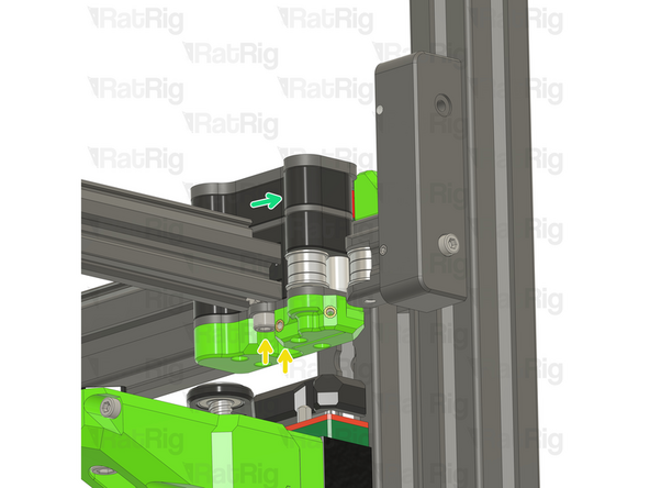
Tighten the marked screw to better secure the gantry to the joiner.
-
This is how the left joiner should look like, carefully inspect your assembly before proceeding.
-
-
-
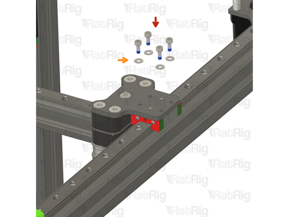
vc4_xy_joiner_upper plate
-
M5x60 Countersink Screw
-
M5x30 Low Profile Screw
-
Insert the screws on the plate and flip the assembly upside down as shown.
-
-
-
Aluminium Spacer 5x8x14mm
-
Insert one Aluminium spacer on each screw
-
vc4_x_endstop printed part
-
Align the printed part and insert it though the aluminium spacers.
-
vc4_xy_joiner_middle plate
-
Align the plate and insert it though the screws.
-
-
-
Install the following components in the order shown in the image:
-
Mini Precision Shim
-
F695ZZ Ball Bearing (Flange at the bottom)
-
695ZZ Ball Bearing
-
F695ZZ Ball Bearing (Flange at the top)
-
Aluminium Spacer 5x8x27mm
-
Aluminium Spacer 5x8x14mm
-
Insert the aluminium spacers on the designated screws.
-
-
-
Take the assembly from Step 16 and insert the printed part holes in the aluminium spaces of the right joiner from the previous Step.
-
Install the following components in the order shown in the image:
-
F695ZZ Ball Bearing (Flange at the bottom)
-
695ZZ Ball Bearing
-
F695ZZ Ball Bearing (Flange at the top)
-
Mini Precision Shim
-
-
-
vc4_xy_joiner_lower plate
-
2x M5x8 Cap Head Screw
-
Insert the screws through the plate, and tighten them to the t-nuts on the 2020 extrusion.
-
M5 Hex Locking nut
-
Thread a M5 hex locking nut in each screw
-
Tighten the screws in each of M5 hex locking nuts were inserted
-
Do not overtighten the screws as too much force can cause the gantry to bind when installed on the V-Core 4.
-
-
-
vc4_xy_trim_left printed part
-
4x M3x8 Cap Head Screw
-
Insert the screws through the printed part and tighten them to the plate
-
Tighten the marked screw to better secure the gantry to the joiner.
-
Set the assembly aside, it will be used further in the Guide
-
-
-
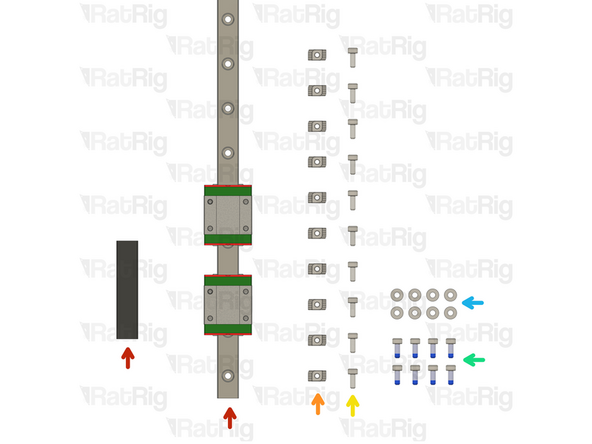
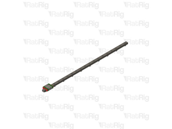
475mm MGN12C Linear Rail & MGN12C carriage holder
-
10x 2020 Drop-in T-Nut - M3
-
10x M3x8 Cap Head Screw
-
V-Core 4 400 - 12 Screws + T-nuts
-
V-Core 4 500 - 14 Screws + T-nuts
-
8x M3x8 Cap Head Screw with blue thread lock
-
The plastic bag has a BT label
-
8x M3 Washer
-
-
-
ONLY remove the second carriage if you are not assembling the IDEX variant.
-
Keeping the second carriage in the X rail will result in poor belt tunning and input shaper results.
-
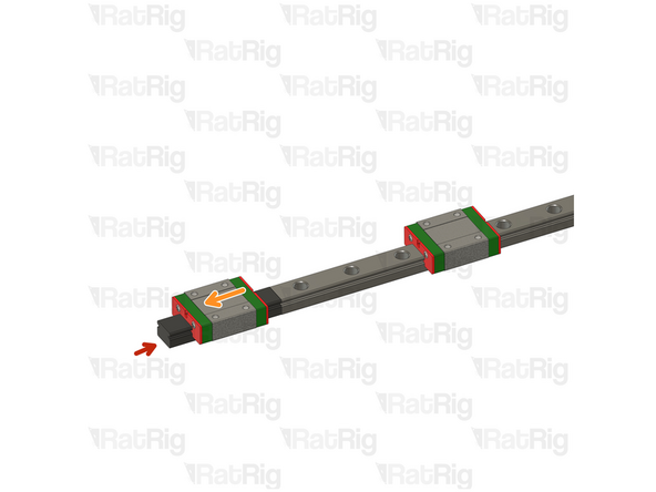
Align the mgn12c carriage mount with the linear rail
-
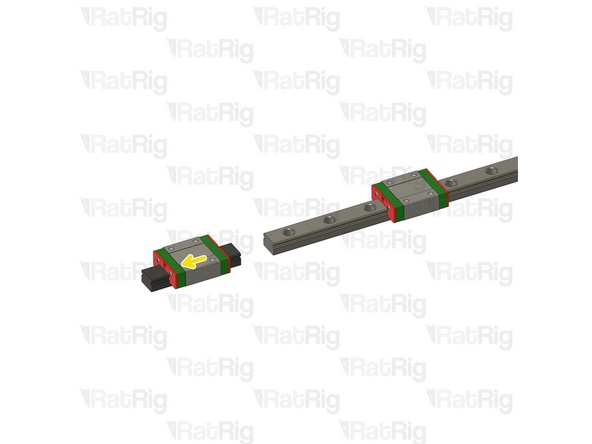
Slowly slide one carriage to the mount
-
Carefully store the carriage, this will be essential for the IDEX upgrade.
-
Ensure the carriage never leaves the mount, to avoid loosing any of the ball bearings inside.
-
-
-
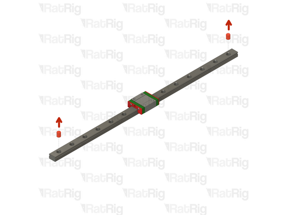
Remove the plastic stops installed in the ends of the linear rail
-
475mm MGN12 Linear Rail
-
10x M3x8 Cap Head Screw
-
10x 2020 Drop-in T-Nut - M3
-
-
-
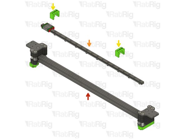
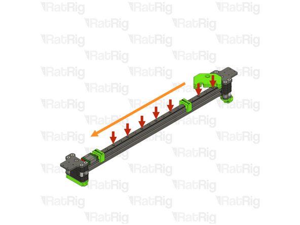
X-Axis Gantry Assembly from Step19
-
Linear rail assembly from the previous Step
-
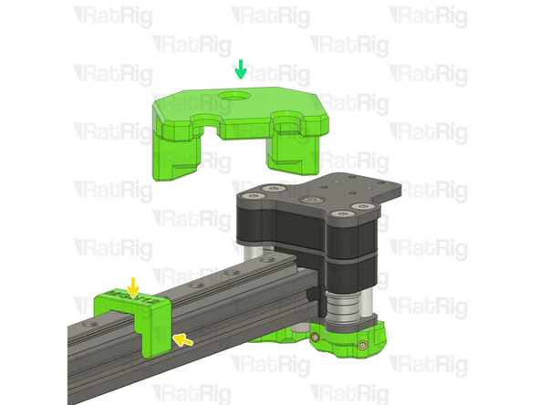
2x align_2020_mgn12
-
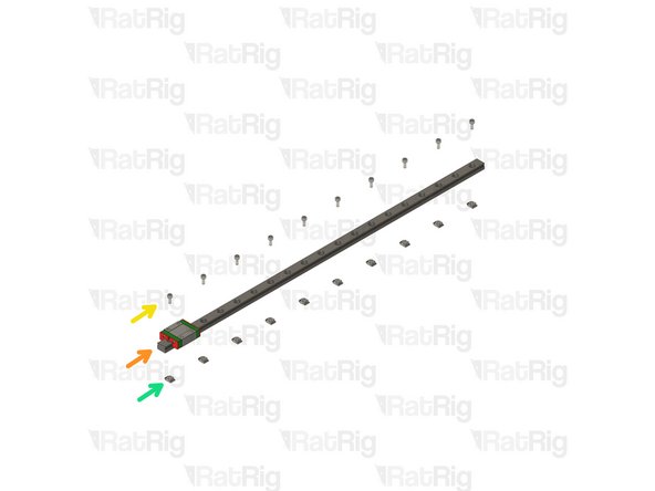
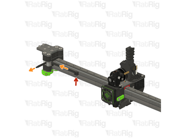
Use the jigs to align the mng12 linear rail on the 2020 extrusion
-
Frame jig from Chapter One
-
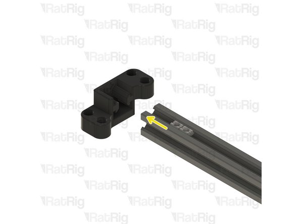
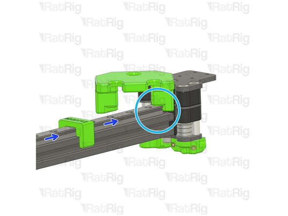
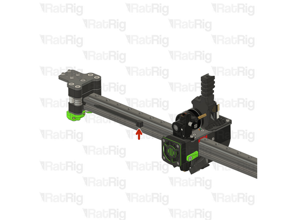
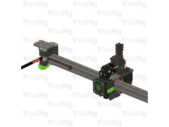
Insert the small tab between the gantry joiner and the linear rail as shown
-
Push the linear rail against the frame jig to ensure they sit flush.
-
-
-
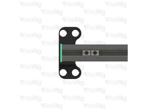
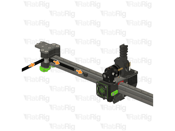
Fasten all M3x8 screws, starting from the jig side. The orange arrow indicates the direction to follow.
-
Do not overtighten the screws as it can cause the linear rail to bind.
-
-
-
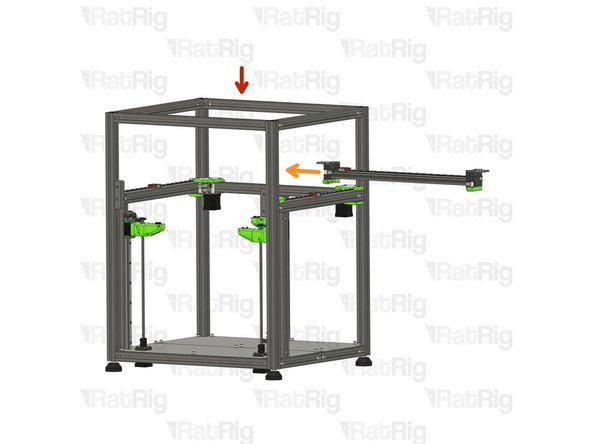
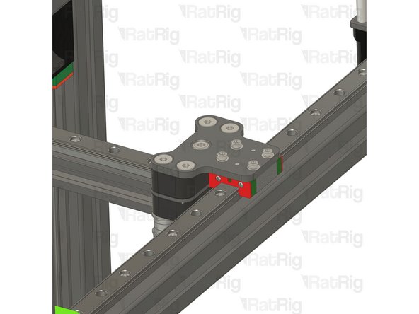
V-Core 4 Frame Assembly
-
X-Axis gantry Assembly
-
Carefully insert the gantry assembly into the V-Core 4 frame from the side, as shown.
-
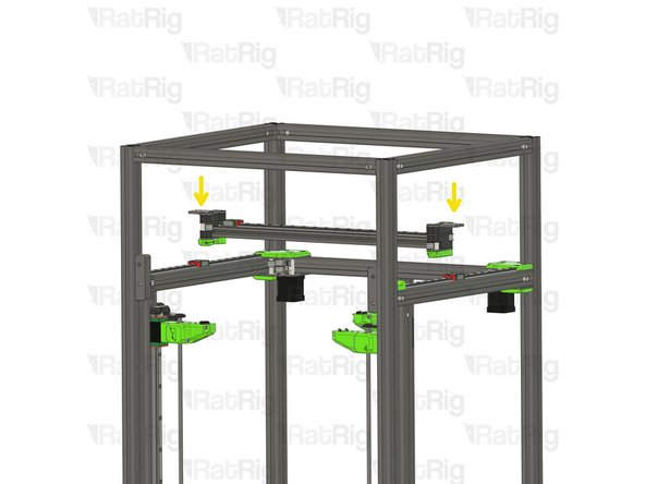
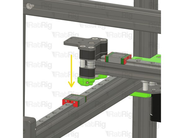
Place the Joiners on top of the linear rail carriages.
-
When installing, keep the gantry's left and right orientation in mind. Installing it in reverse will prevent the belt routing from working.
-
-
-
4x M3x8 Cap Head Screw with threadlock (blue on ends of screw threads)
-
4x M3 washer
-
Insert an M3x8 Cap Head screw with an M3 washer through the joiner plate and tighten it to the linear rail carriage
-
Don't overtighten the screws as it can cause the gantry to bind in the Y direction
-
-
-
4x M3x8 Cap Head Screw
-
4x M3 washer
-
Insert an M3x8 Cap Head screw with an M3 washer through the joiner plate and tighten it to the linear rail carriage
-
Don't overtighten the screws as it can cause the gantry to bind in the Y direction
-
-
-
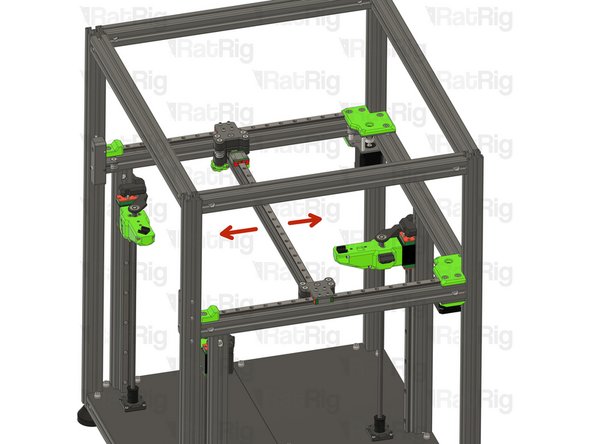
Test the movement of the y-axis over the full travel distance
-
Small changes in resistance are normal, but becoming much harder to push, or binding completely are not
-
If the Gantry feels hard to push, you can undo the M3x8 Cap Head screws installed on the previous Steps a quarter of a turn, ensuring there is no play between the joiner plates and the linear rail carriages
-
-
-
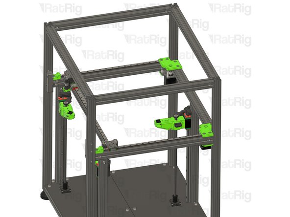
Move the gantry to the front.
-
Both Joiners must hit the Y bumper printed parts at the same time.
-
An exaggerated example of a misaligned gantry, there is a gap on one side, but not the other.
-
The right side sits flush with the Y bumper, or vice versa.
-
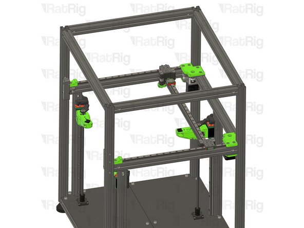
If your gantry isn't bumping into both printed parts at the same time, follow the next steps:
-
Gently loosen all screws in both joiners.
-
Push the joiners against the Y bumper printed parts by hand.
-
Firmly Retighten all screws on both Joiners and go back to Step 27
-
-
-
Take the belt package inside the HW3693MK - Rat Rig V-Core 4.0 - Base Hardware Pack - All Versions and cut it in half, one half will be used for the top belt path and the other for the lower belt path.
-
If you are building the hybrid machine you have 2 belt packages, you should use the longest one at this stage.
-
-
-
This step is not mandatory, it's just a Rat Rig tip on how to feed the belts on the idlers.
-
Zip Tie
-
The wider the zip tie is, the easier the process will be
-
Bend the tip of the zip tie a little bit and feed it between the joiner assembly and the idler, as shown
-
-
-
Insert the belt between the zip tie and the idler
-
Slowly feed the belt and pull the zip tie at the same time
-
-
-
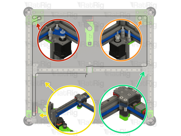
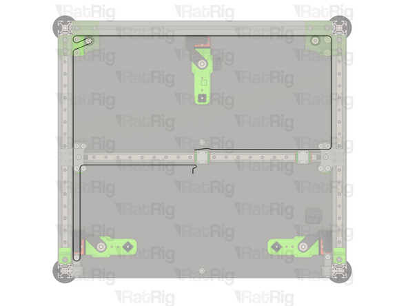
Ensure the belt teeth are facing the stepper motor pulleys.
-
Take one end of the top CoreXY belt, and feed it as shown:
-
Feed the belt through the left stepper motor bearing stacks.
-
Feed the belt behind the left xy_joiner, through the front tensioner and finally the front bearing stack on the xy_joiner.
-
Take the other end of the top CoreXY belt, and feed it as shown:
-
Feed the belt through the right stepper motor bearing stacks.
-
Feed the belt around the rear bearing stack on the xy_joiner.
-
Do not cut the excess belt at this stage.
-
-
-
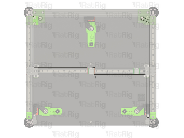
Ensure the belt teeth are facing the stepper motor pulleys.
-
Ensure the belt teeth are facing the stepper motor pulleysTake one end of the lower CoreXY belt, and feed it as shown:
-
Feed the belt through the left stepper motor bearing stacks.
-
Feed the belt around the rear bearing stack on the xy_joiner.
-
Take the other end of the top CoreXY belt, and feed it as shown:
-
Feed the belt through the right stepper motor bearing stacks.
-
Feed the belt behind the left xy_joiner, through the front tensioner and finally the front bearing stack on the xy_joiner.
-
Do not cut the excess belt at this stage.
-


Cancel: I did not complete this guide.
46 other people completed this guide.
