
Steps
29
- 07. Bed Arm Assemblies 29 steps

User-Contributed Guide
This guide is not managed by the site's staff.
Quiz
0
Introduction
Please note: The lead screw measurements provided in this guide are based upon building a 300x300 V-Core 3.
If you are building a machine of a different size, please refer to the following list for the correct lead screw length for your machine:
- 200x200: 3x 280mm lead screws
- 300x300: 3x 380mm lead screws
- 400x400: 3x 480mm lead screws
- 500x500: 3x 580mm lead screws
-
-
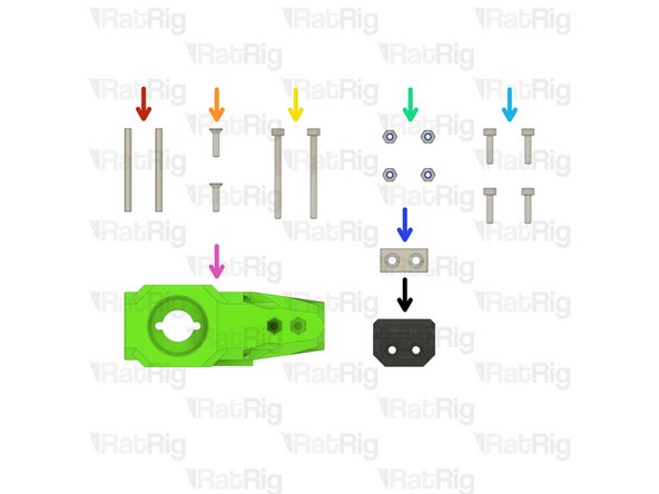
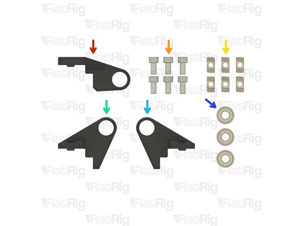
1x bed_arm_right_3.1 Printed Part
-
1x bed_arm_left_3.1 Printed Part
-
4x M3x12 Countersink Screw
-
4x 3x35mm Dowel Pin
-
2x Neodymium Magnet
-
4x M3 Nylon Locking Hex Nut
-
-
-
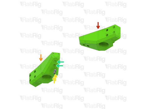
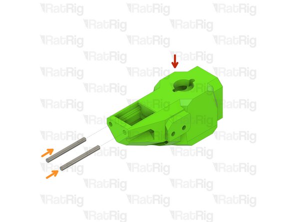
bed_arm_left_3.1 Printed Part
-
bed_arm_right_3.1 Printed Part
-
3x35mm Dowel Pin
-
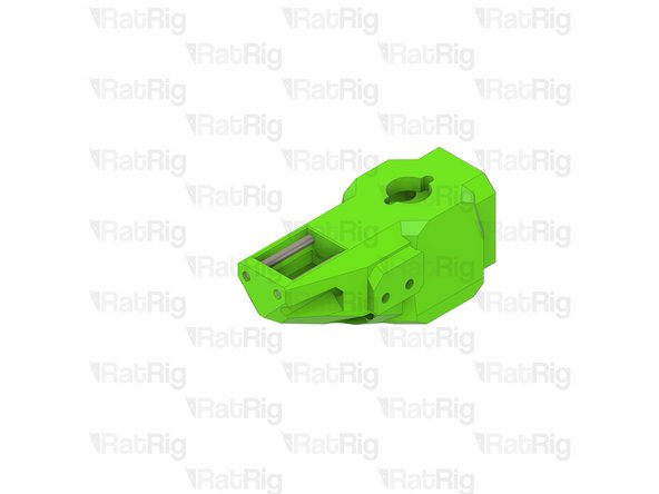
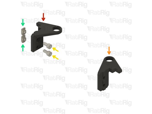
Insert two dowel pins into each arm as shown
-
Please note: The dowel pins are quite a tight fit. It is recommended to use a pair of pliers to install them by twisting each pin in the same manner you would install a screw
-
Do not use excessive force to install the pins as this can cause damage to the printed part
It should be 4x35mm Dowel Pin instead if 3x35mm Dowel Pin
Pieter Van Nueten - Resolved on Release Reply
3x35mm means 3mm diameter x 35 mm length dowel pins. The quantity of 4 was stated in the prior step.
Jeremy -
-
-
-
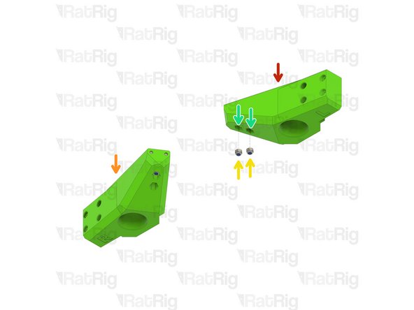
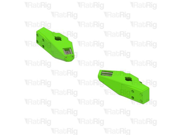
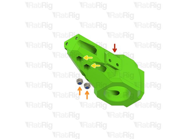
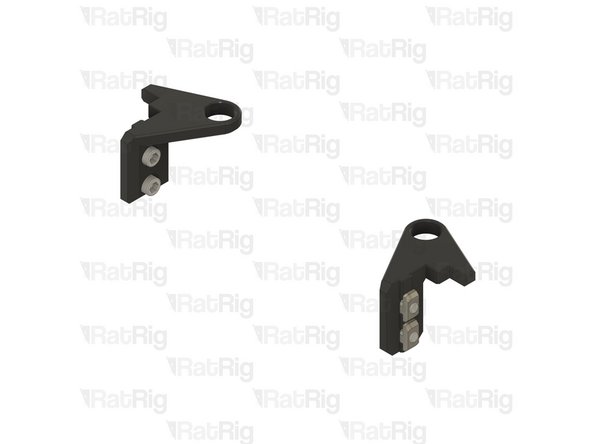
Left Bed Arm Assembly
-
Right Bed Arm Assembly
-
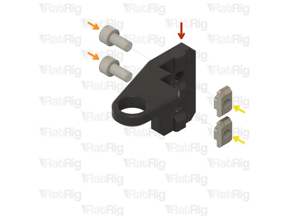
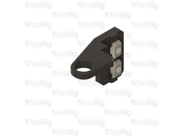
M3 Nylon Locking Hex Nut
-
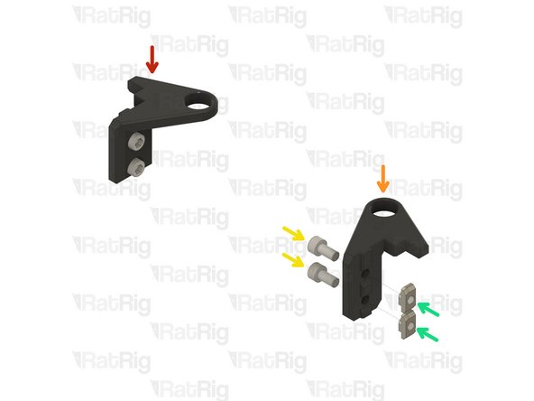
Insert an M3 nut into each marked position
The nut holes were very tight for me, so I took a large hex driver and lightly hammered them into place
Henrik Paul - Resolved on Release Reply
-
-
-
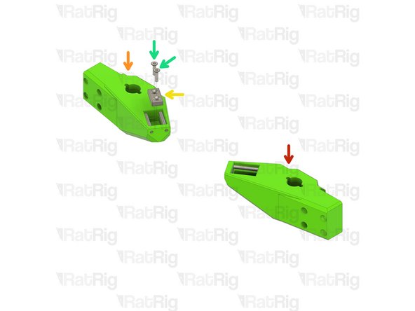
Left Bed Arm Assembly
-
Right Bed Arm Assembly
-
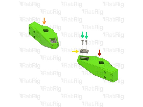
Neodymium Magnet
-
M3x12 Countersink Screw
-
Install two M3x12 countersink screws into each magnet and then install them into the arms as shown
-
Take care not to over tighten the M3x12 screws as you can crack the magnets and/or damage the printed parts
-
Set these assemblies aside until Step 7
-
-
-
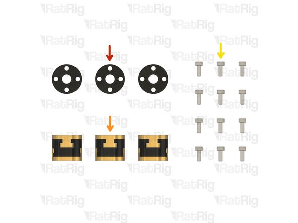
3x TR8x4 POM Lead screw Nut
-
3x Rat Rig Bi-Material Lead Screw Decoupler
-
12x M3x8 Cap Head Screw
-
-
-
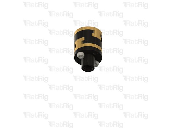
Rat Rig Bi-Material Lead Screw Decoupler
-
TR8x4 POM Lead screw Nut
-
M3x8 Cap Head Screw
-
Assemble all three lead screw decouplers as shown. Set one aside until Step 13, keep the other two for the next step
-
-
-
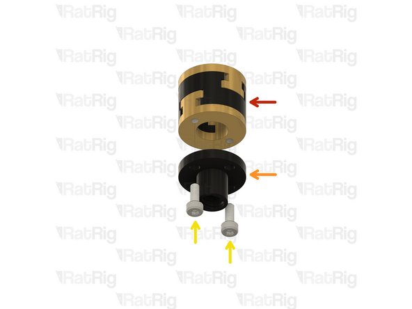
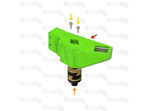
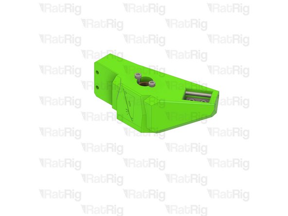
Left bed arm assembly
-
Lead screw decoupler assembly
-
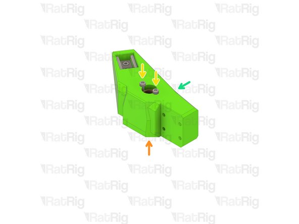
M3x8 Cap Head Screw
-
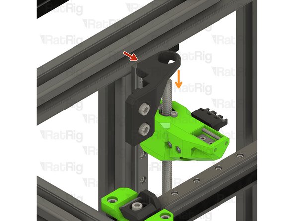
Install a lead screw decoupler assembly into each arm as shown
-
Take care not to over tighten the M3x8 screws as you damage the printed parts
-
Right bed arm assembly
-
-
-
2x 3x35mm Dowel Pin
-
2x M3x12 Countersink Screw
-
2x M3x35 Cap Head Screw
-
4x M3 Nylon Locking Hex Nut
-
4x M3x12 Cap Head Screw
-
1x Neodymium Magnet
-
1x bed_arm_rear_3.1 Printed Part
-
1x bed_cable_relief_3.1 Printed Part
-
-
-
bed_arm_rear_3.1 Printed Part
-
3x35mm Dowel Pin
-
Insert two dowel pins into the arm as shown
-
Please note: The dowel pins are quite a tight fit. It is recommended to use a pair of pliers to install them by twisting each pin in the same manner you would install a screw
-
Do not use excessive force to install the pins as this can cause damage to the printed part
It should be 2x35mm Dowel Pin instead if 3x35mm Dowel Pin
Pieter Van Nueten - Resolved on Release Reply
I think the author makes reference to the size of the pin, not the quantity. Assuming they are two elements as it can be viewed in the picture.
Albert -
-
-
-
Rear bed arm assembly
-
M3 Nylon Locking Hex Nut
-
Insert an M3 nut into each marked position
-
-
-
Rear bed arm assembly
-
Neodymium Magnet
-
M3x12 Countersink Screw
-
Install two M3x12 countersink screws into the magnet and then install it into the arm as shown
-
Take care not to over tighten the M3x12 screws as you can crack the magnet and/or damage the printed part
-
-
-
Rear bed arm assembly
-
M3 Nylon Locking Hex Nut
-
bed_cable_relief_3.1 Printed Part
-
M3x35 Cap Head Screw
-
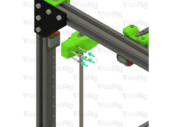
Install the M3x35 screws through the bed_cable_relief_3.1 printed part, rear bed arm, and fasten them into the M3 nylon locking nuts
-
Take care not to over tighten the M3x35 screws as you can damage the printed parts
-
-
-
V-Core 3.1 Frame Assembly
-
Rear bed arm assembly
-
M3x12 Cap Head Screw
-
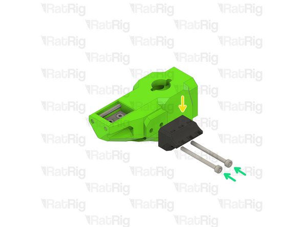
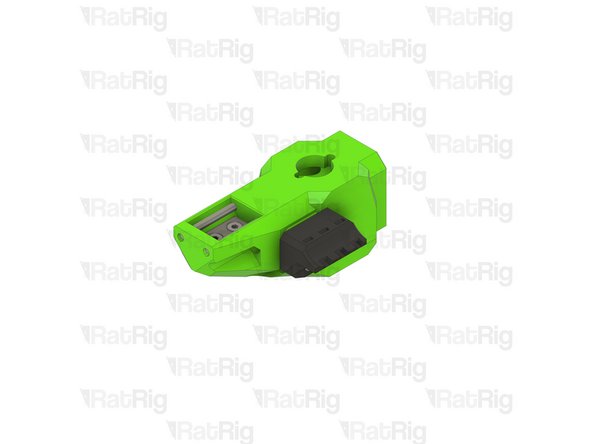
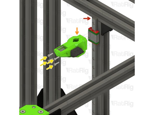
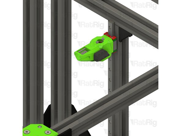
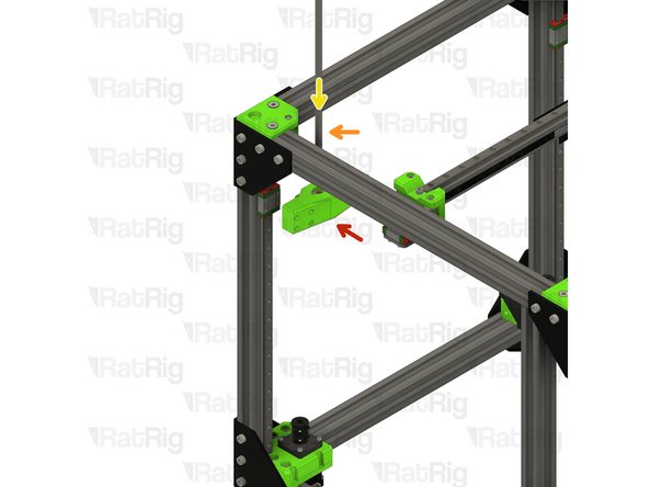
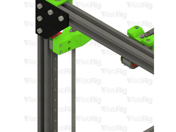
Install the M3x12 screws into the arm as shown, then fasten the arm to the rear linear rail carriage
-
Lead screw decoupler assembly from Step 6
-
M3x8 Cap Head Screw
-
Install a lead screw decoupler assembly into the rear arm as shown
-
Take care not to over tighten the M3 screws as you damage the printed part
I used a 5mm drill bit from the front to make the holes large enough to push the m3 screws through to the back - then a long allen wrench to start them. I had about 1 mm through the back before trying to mount them on the block
david wilson - Resolved on Release Reply
I clip the centering tool at the top of the back rail as a reminder.
Brentley Beerline - Resolved on Release Reply
If you are as stupid or unlucky as I was you’ll pull the carriage over the end of the linear rail while trying to install the rear arm ;) I recomment putting a piece of tape on the end of the rail to avoid that. It only takes a few minutes to find the small steel balls and put them into the carriage again , but it still make you feel less intelligent and you are screwed if you cannot find all the balls.
Kenneth Jensen - Resolved on Release Reply
I found it easier to use a long needle nose pliers to insert the M3x12 cap screws into the rear bed arm assembly and push them into the holes with a long hex wrench. If you try to go through the holes as marked, you run the risk of the cap screw falling off the wrench before it seats into the other hole.
Matt Modica - Resolved on Release Reply
-
-
-
Rear bed arm assembly
-
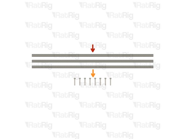
380mm TR8x4 Lead Screw
-
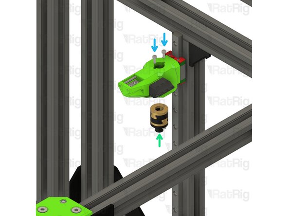
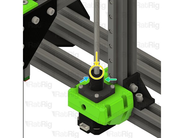
Install the lead screw through the rear bed arm and decoupler
-
Do not force the lead screw through the POM nut on the decoupler as this can cause damage. It should thread through smoothly
-
Rigid Lead Screw Coupler
-
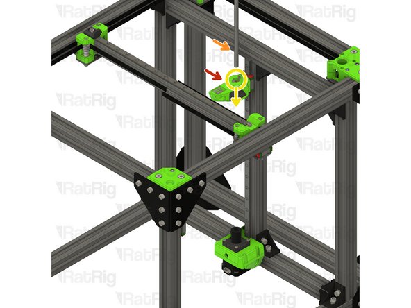
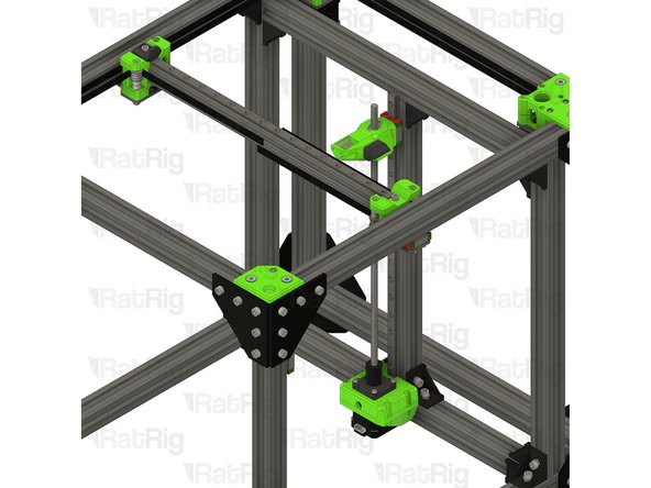
Continue threading the lead screw through the arm until it reaches the rigid lead screw coupler on the rear Z-axis motor mount
-
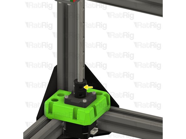
Insert the lead screw fully into the rigid coupler
-
Fasten the marked M3 screw to secure the lead screw to the NEMA17 motor
-
-
-
Front right bed arm assembly
-
380mm TR8x4 lead screw
-
Install the lead screw through the front bed arm and decoupler
-
Do not force the lead screw through the POM nut on the decoupler as this can cause damage. It should thread through smoothly
-
Continue threading the lead screw through the arm until it reaches the rigid lead screw coupler on the front right Z-axis motor mount
-
M3x20 Cap Head Screw
-
Install each screw through the bed arm assembly as shown, then fasten the arm to the linear rail carriage
-
-
-
Rigid Lead Screw Coupler
-
Insert the lead screw fully into the rigid coupler
-
Fasten the marked M3 screw to secure the lead screw to the NEMA17 motor
-
-
-
Front left bed arm assembly
-
380mm TR8x4 lead screw
-
Install the lead screw through the front bed arm and decoupler
-
Do not force the lead screw through the POM nut on the decoupler as this can cause damage. It should thread through smoothly
-
Continue threading the lead screw through the arm until it reaches the rigid lead screw coupler on the front left Z-axis motor mount
-
M3x20 Cap Head Screw
-
Install each screw through the bed arm assembly as shown, then fasten the arm to the linear rail carriage
-
-
-
Rigid Lead Screw Coupler
-
Insert the lead screw fully into the rigid coupler
-
Fasten the marked M3 screw to secure the lead screw to the NEMA17 motor
-
-
-
1x lead_screw_constraint_rear_3.1 Printed Part
-
6x M6x12 Cap Head Screw
-
6x 3030 Drop-in T-Nut - M6
-
1x lead_screw_constraint_front_left_3.1 Printed Part
-
1x lead_screw_constraint_front_right_3.1 Printed Part
-
3x F688ZZ Ball Bearing
i followed the order of the instructions, but had to use a large pliers to seat the bearing when it was placed on the support.
Also curious what distance from the top the bearing should end up. No real instructions on that
david wilson - Resolved on Release Reply
It must be aligned with the horizontal 2020 extrusion or with the end of the rail, depending on the screw that you are aligning.
Albert -
I totally agree with Roberto. I simply used a quick grip to insert them, but it’s so much easier to do it before installation. Be aware of the correct orientation of the bearing. The flange is to be on top(opposite side of the screws) but this is easy to see in the instructions below.
Kenneth Jensen - Resolved on Release Reply
Beware that the bearing part might be difficult if done in the order suggested. I had to disassemble and do the bearing outside and use a clamp to force it. Depending how your printed your parts it might be a real tight fit. Lower the arm a bit instead of the top so that the constraint can drop in with the lead screw having more ‘play’. If not you wont be able to get it in if you do the bearing first.
Roberto Hernandez - Resolved on Release Reply
-
-
-
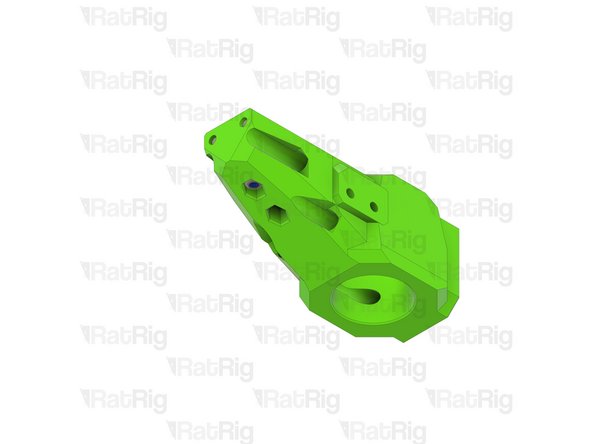
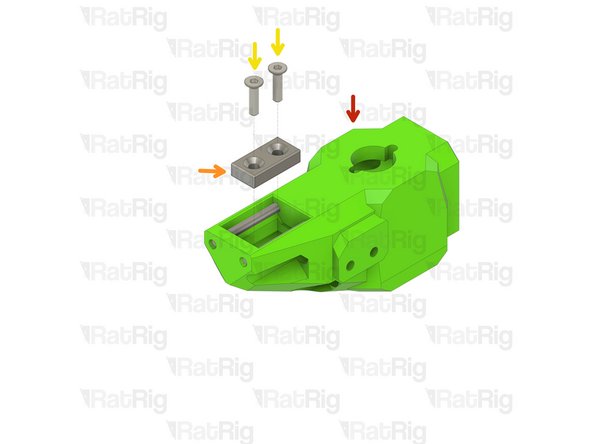
lead_screw_constraint_rear_3.1 Printed Part
-
M6x12 Cap Head Screw
-
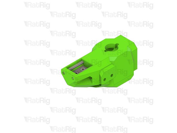
Insert an M6x12 cap head screw into each position on the lead screw constraint as shown
-
3030 Drop-in T-Nut - M6
-
Loosely thread a 3030 T-Nut onto each of the M6x20 screws. Do not tighten them at this point
-
-
-
lead_screw_constraint_left_3.1 Printed Part
-
lead_screw_constraint_right_3.1 Printed Part
-
M6x12 Cap Head Screw
-
Insert an M6x12 cap head screw into each position on the lead screw constraint as shown
-
3030 Drop-in T-Nut - M6
-
Loosely thread a 3030 T-Nut onto each of the M6x20 screws. Do not tighten them at this point
-
-
-
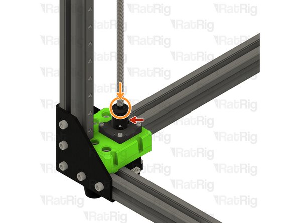
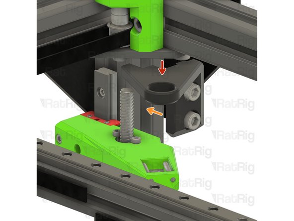
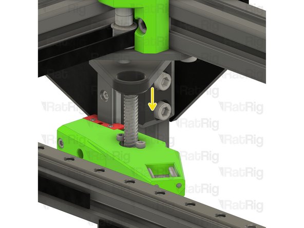
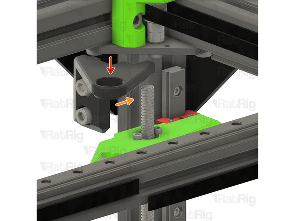
Rear lead screw constraint assembly from Step 21
-
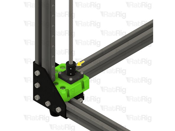
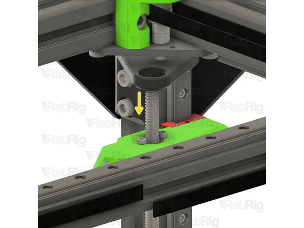
Position the constraint assembly so that the rear lead screw passes through the hole
-
Rotate the constraint assembly clockwise and fit it to the rear 3030 extrusion as shown
-
Push the constraint assembly upwards until it touches the horizontal 3030 extrusion
Useful comment! I also applied small amount of liquid soap on the printed parts in the bearing bushing.
Mihály Farkas - Resolved on Release Reply
Bearings were a really tight fit in my constraint part. I installed them before assembling onto the frame. This worked great.
Lane Slabaugh - Resolved on Release Reply
-
-
-
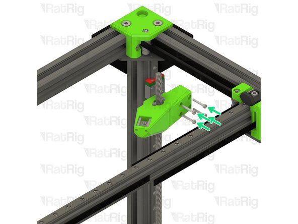
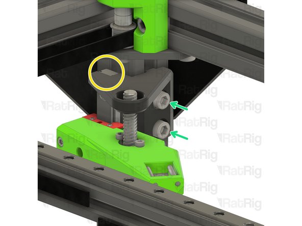
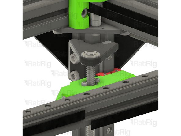
M6x12 Cap Head Screw
-
Fasten both M6x12 screws to secure the constraint assembly to the V-Core 3.1 frame
-
Take care not to over tighten the M6 screws as you damage the printed part
-
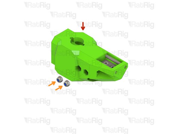
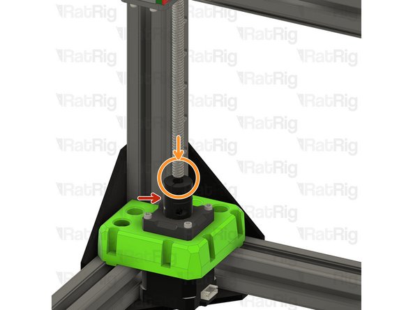
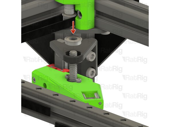
F688ZZ Ball Bearing
-
Fit the bearing onto the lead screw and into the constraint assembly as shown
-
-
-
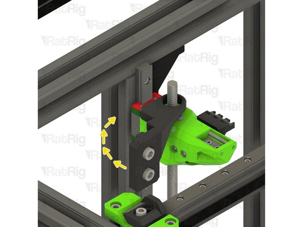
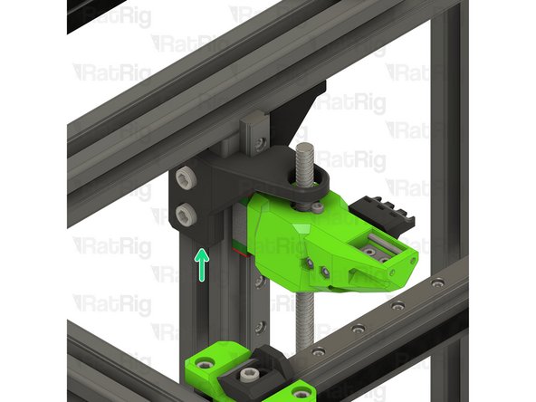
Right lead screw constraint assembly from Step 22
-
Fit the constraint assembly to the frame as shown
-
Push the constraint assembly downwards until its top is flush with the top of the linear rail
-
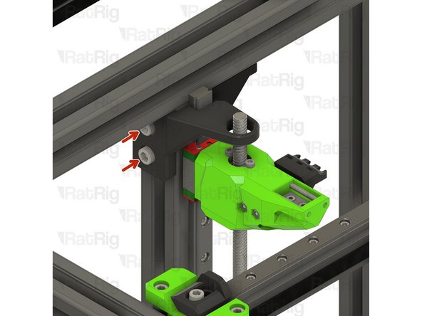
Fasten both M6x12 screws to secure the constraint assembly to the V-Core 3.1 frame
-
-
-
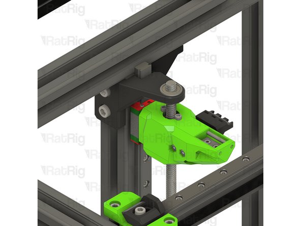
F688ZZ Ball Bearing
-
Fit the bearing onto the lead screw and into the constraint assembly as shown
-
-
-
Left lead screw constraint assembly from Step 22
-
Fit the constraint assembly to the frame as shown
-
Push the constraint assembly downwards until its top is flush with the top of the linear rail
-
Fasten both M6x12 screws to secure the constraint assembly to the V-Core 3.1 frame
-
-
-
F688ZZ Ball Bearing
-
Fit the bearing onto the lead screw and into the constraint assembly as shown
-


Cancel: I did not complete this guide.
30 other people completed this guide.