
Steps
21
- 02. Z-Axis Assemblies 21 steps

User-Contributed Guide
This guide is not managed by the site's staff.
Quiz
0
-
-
2x lead_screw_motor_cage_front_3.1 printed part
-
2x Axial Thrust Bearing
-
2x pillow_block printed part
-
2x Rigid Lead Screw Coupler
-
2x 48mm NEMA17 Stepper Motor
-
-
-
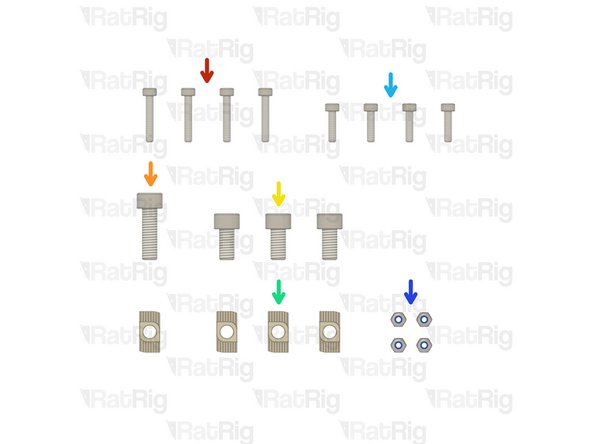
8x M3x18 Cap Head Screw
-
8x M6x20 Cap Head Screw
-
8x 3030 Drop-in T-Nut - M6
-
8x M3 Nylon Locking Hex Nut
-
8x M3x12 Cap Head Screw
-
-
-
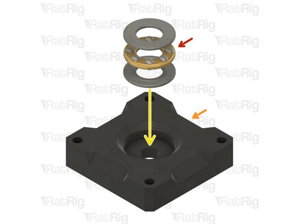
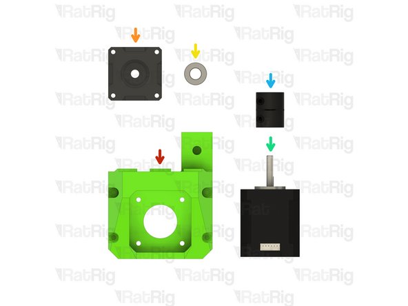
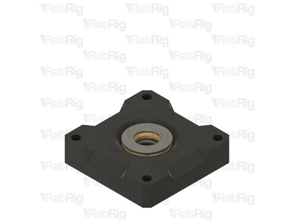
Axial Thrust Bearing
-
The axial thrust bearing has three components. Two end caps and an inner bearing assembly.
-
pillow_block printed part
-
Assemble the axial thrust bearing into the pillow_block as shown
-
Make sure that the thrust bearing is fully inserted into the printed part. The top ring of the thrust bearing should be flush with the top of the pillow_block.
-
If desired, you may add a drop of light oil to the inner bearing assembly of the thrust bearing
-
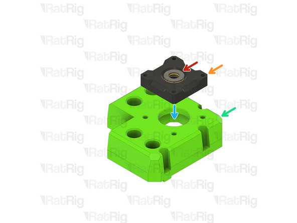
lead_screw_motor_cage_front_3.1 printed part
-
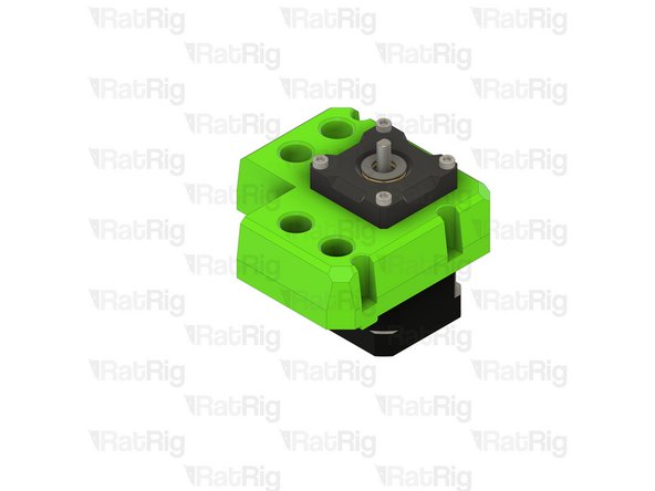
Place the pillow_block assembly atop the lead_screw_motor_cage_front_3.1 in preparation for the next step
-
-
-
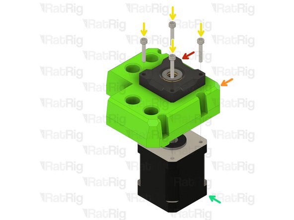
pillow_block and axial thrust bearing assembly
-
lead_screw_motor_cage_front_3.1 printed part
-
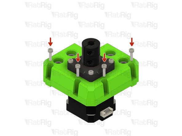
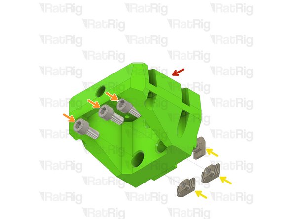
M3x18 Cap Head Screw
-
48mm NEMA17 Stepper Motor
-
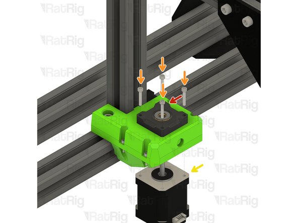
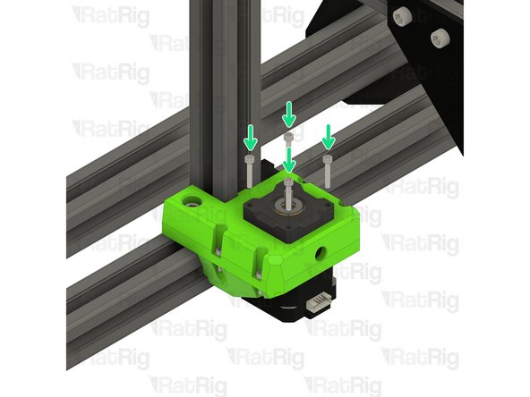
Insert the NEMA17 motor into the lead_screw_motor_cage printed part, as shown
-
Insert each M3x18 cap head screw through the pillow block, the lead screw motor cage, and fasten them into the NEMA17 motor
-
Take care not to over tighten the M3x18 screws as you can damage the printed parts
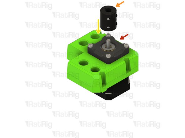
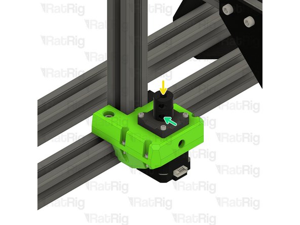
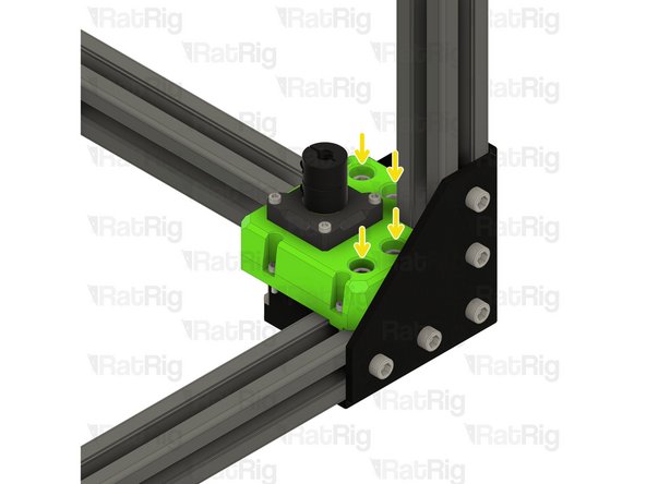
To add a little more detail on the motor orientation:
The Fusion 360 CAD assembly shows that both motor plugs should face the rear of the 3D printer. So, for each of these two motor mounts the plug will be oriented differently. In other words, don’t build both of them identically to each other.
In Step 4 here you’re building up the front right motor mount. If you’re looking at the first image, the orange and red arrows are pointing at the side where the plug should be. This can also be seen in Step 8 as mentioned in the previous comments.
Then in Step 9 when you build up the front left motor mount, the connector should face a different side. Once again looking at the first image here in Step 4, it will be the side that the green arrow is facing.
The CAD assembly model available via OnShape shows a different orientation of the motor electrical connector from that shown in Step 8, below. Maybe either one is OK, as long as the connector is not facing a 3030 extrusion?
John Vybiral - Resolved on Release Reply
Check the correct orientation of the plug on the motor in step 8
Kenneth Jensen - Resolved on Release Reply
-
-
-
Assembly from the previous step
-
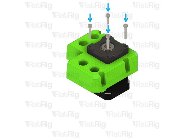
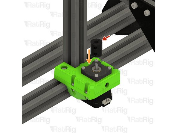
Rigid Lead Screw Coupler
-
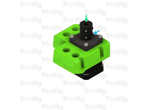
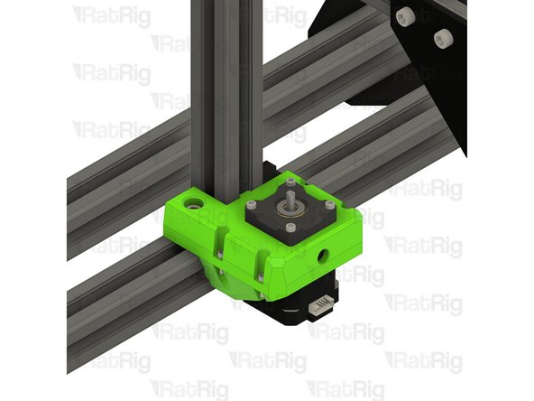
Install the lead screw coupler on to the exposed shaft of the NEMA17 motor
-
Apply downward pressure to the top of the lead screw coupler whilst tightening the marked screw
-
Tighten the marked M3 screw to secure the lead screw coupler to the motor shaft
-
-
-
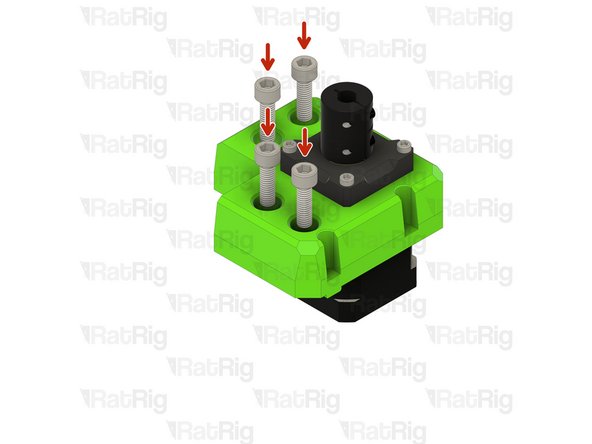
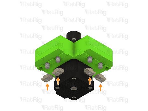
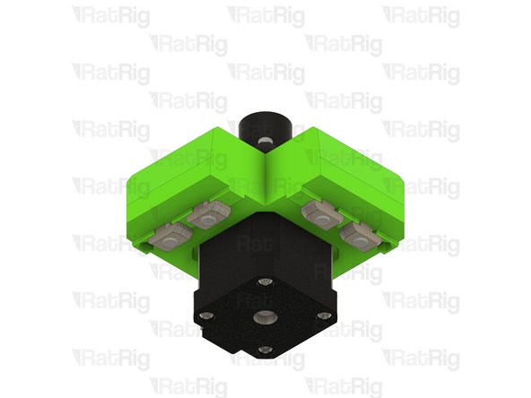
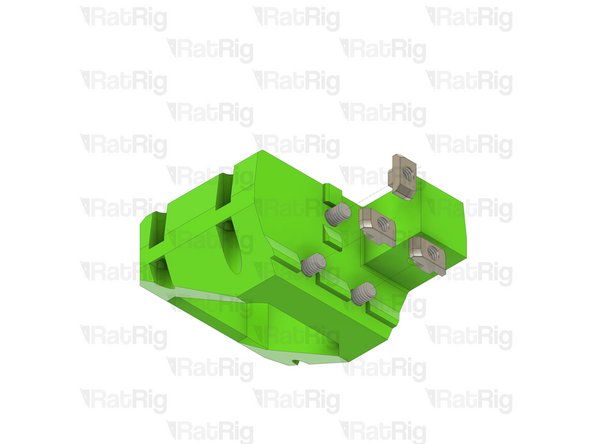
M6x20 Cap Head Screw
-
Insert each M6x20 cap head screw into the lead screw motor mount as shown
-
3030 Drop-in T-Nut - M6
-
Loosely thread a 3030 T-Nut onto each of the M6x20 screws. Do not tighten them at this point.
-
-
-
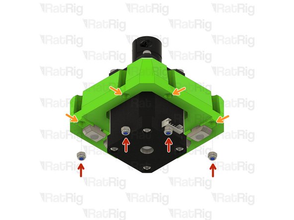
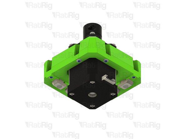
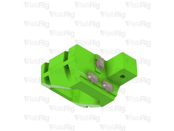
M3 Nylon Locking Hex Nut
-
Insert an M3 nut into each marked position
-
Do not worry about fully seating the M3 nuts into the mount, this will be done in the next step
The ”M3 nylon hex locking nut” is the bag called just “hex locking nut M3”. The nuts are metal, they just have a nylon insert to lock the screw
Henrik Paul - Resolved on Release Reply
-
-
-
M3x12 Cap Head Screw
-
Insert each M3x12 cap head screw into the lead screw motor mount as shown
-
Slowly tighten the each screw to seat the M3 nut below
-
Take care not to over tighten the M3x12 screws as you can damage the printed part
-
These screws are used to mount the optional printed trim part when using a base panel
The trim looks to be for the optional 3.1 enclosure base panel, and the trim files are with the enclosure printed parts.
Brian Pickens - Resolved on Release Reply
-
-
-
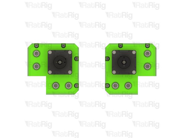
Repeat Steps 3 to 8 to assemble the right Z-axis motor mount
-
Once you have both front Z-axis motor mounts assembled as shown, proceed to the next step
-
-
-
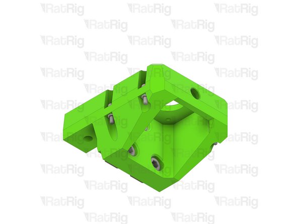
lead_screw_motor_cage_rear_3.1 printed part
-
pillow_block printed part
-
Axial Thrust Bearing
-
48mm NEMA17 Stepper Motor
-
Rigid Lead Screw Coupler
-
-
-
4x M3x18 Cap Head Screw
-
1x M6x20 Cap Head Screw
-
3x M6x12 Cap Head Screw
-
4x 3030 Drop-in T-Nut - M6
-
4x M3x12 Cap Head Screw
-
4x M3 Nylon Locking Hex Nut
-
-
-
Axial Thrust Bearing
-
The axial thrust bearing has three components. Two end caps and an inner bearing assembly.
-
pillow_block printed part
-
Assemble the axial thrust bearing into the pillow_block as shown
-
Make sure that the thrust bearing is fully inserted into the printed part. The top ring of the thrust bearing should be flush with the top of the pillow_block.
-
If desired, you may add a drop of light oil to the inner bearing assembly of the thrust bearing
-
Set the pillow block assembly aside until Step 17
-
-
-
lead_screw_motor_cage_rear_3.1 printed part
-
M6x12 Cap Head Screw
-
Insert each M6x12 cap head screw into the lead screw motor cage as shown
-
3030 Drop-in T-Nut - M6
-
Loosely thread a 3030 T-Nut onto each of the M6x20 screws. Do not tighten them at this point.
-
-
-
M3 Nylon Locking Hex Nut
-
Insert an M3 nut into each marked position
-
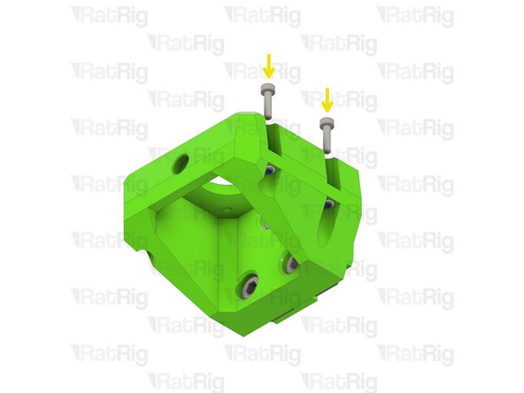
M3x12 Cap Head Screw
-
Insert each M3x12 cap head screw into the lead screw motor cage as shown
-
Slowly tighten the each screw to seat the M3 nut below
-
Take care not to over tighten the M3x12 screws as you can damage the printed part
-
These screws are used to mount the optional printed trim part when using a base panel
-
-
-
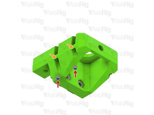
M3 Nylon Locking Hex Nut
-
Insert an M3 nut into each marked position
-
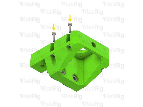
M3x12 Cap Head Screw
-
Insert each M3x12 cap head screw into the lead screw motor cage as shown
-
Slowly tighten the each screw to seat the M3 nut below
-
Take care not to over tighten the M3x12 screws as you can damage the printed part
-
These screws are used to mount the optional printed trim part when using a base panel
-
-
-
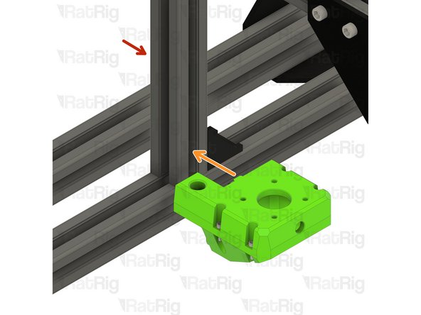
V-Core 3.1 Frame Assembly
-
Install the rear lead screw motor cage onto the frame as shown
-
The rear lead screw motor cage is designed so that it can only be installed in the correct position. If the part doesn't fit correctly, check the position of the 3030 T-nuts and make sure it is positioned as shown
-
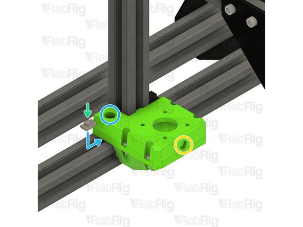
Tighten the three M6x12 screws inside the rear lead screw motor cage to secure it to the frame. The top M6x12 screw can be accessed through the marked hole
-
3030 Drop-in T-Nut - M6
-
Place the 3030 T-nut into the extrusion channel and slide it under the lead screw motor cage as shown. Position the T-nut so that you are able to see it through the marked hole
-
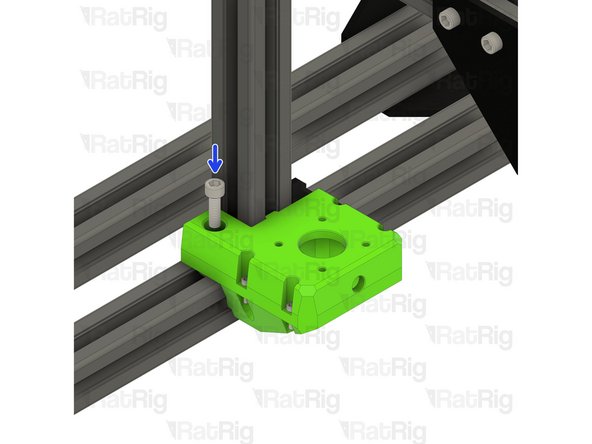
M6x20 Cap Head Screw
-
Insert the M6x20 screw as shown and secure it into the previously positioned 3030 T-nut
-
-
-
pillow_block and axial thrust bearing assembly
-
M3x18 Cap Head Screw
-
48mm NEMA17 Stepper Motor
-
Insert the NEMA17 motor into the rear lead screw motor cage printed part, as shown
-
Insert each M3x18 cap head screw through the pillow block, the lead screw motor cage, and fasten them into the NEMA17 motor
-
Take care not to over tighten the M3x18 screws as you can damage the printed parts
-
-
-
Rigid Lead Screw Coupler
-
Install the lead screw coupler on to the exposed shaft of the NEMA17 motor
-
Apply downward pressure to the top of the lead screw coupler whilst tightening the marked screw
-
Tighten the marked M3 screw to secure the lead screw coupler to the motor shaft
Hold off putting on the coupler as you would need to then take it off again to install the linear rail
Absolute Prodigy - Resolved on Release Reply
-
-
-
V-Core 3.1 Frame Assembly - Front Left Corner
-
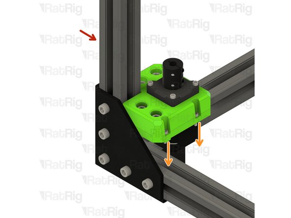
Install the front left lead screw motor cage onto the frame as shown
-
The front lead screw motor cages are designed so that they can only be installed in the correct position. If the part doesn't fit correctly, check the position of the 3030 T-nuts and make sure the assembly is positioned as shown
-
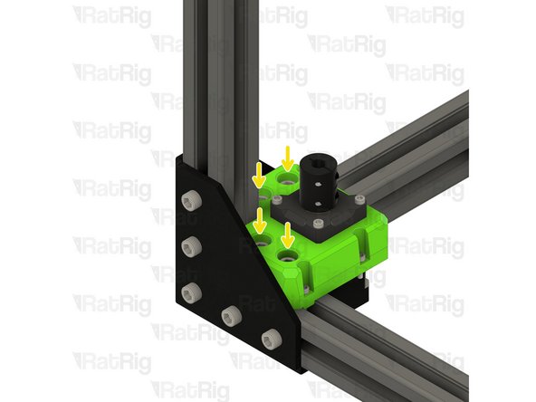
Tighten the four marked M6x12 screws to secure the front lead screw motor cage to the frame
-
-
-
V-Core 3.1 Frame Assembly - Front Right Corner
-
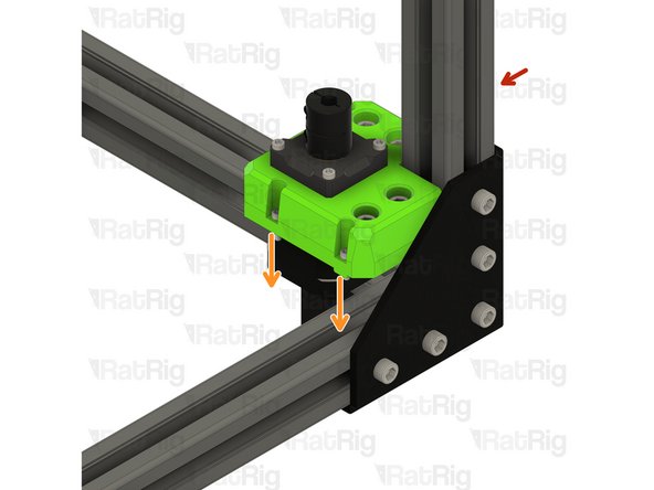
Install the front right lead screw motor cage onto the frame as shown
-
The front lead screw motor cages are designed so that they can only be installed in the correct position. If the part doesn't fit correctly, check the position of the 3030 T-nuts and make sure the assembly is positioned as shown
-
Tighten the four marked M6x20 screws to secure the front lead screw motor cage to the frame
-


Cancel: I did not complete this guide.
35 other people completed this guide.
One Comment
As you begin this section, remember that you need to rotate the printer upright, from the inverted assembly position from the last section.
jay@waveshaper.com - Resolved on Release Reply