Introduction
BEFORE STARTING:
Before beginning this guide, you must prepare all the necessary wires for the assembly. Below is a list of the required wires. The following nomenclature will be used: (Wire Length)_(AWG)_(Wire Color)_(A-End Connector)_(B-End Connector)_(ID number).
Use a small piece of tape to label each wire to ensure a smooth assembly process.
- 120mm - 16AWG RED (A-Fork, B-Fork) (4)
- 800mm - 16AWG RED (A-Fork, B-Ferrule) (5)
- 800mm - 16AWG RED (A-Fork, B-Fork) (6)
- 600mm - 16AWG RED (A-Fork, B-Ferrule) (7)
- 600mm - 16AWG BLACK (A-Fork, B-Ferrule) (8)
- 700mm - 16AWG BLACK (A-Fork, B-Ferrule) (9)
- 100mm - 16AWG BLACK (A-Fork, B-Ferrule) (10)
- 900mm - Multicore 2 Conductor - 24AWG (A-2xFerrule, B-2xFerrule) (11)
- 200mm - 18AWG BROWN (A-Fork, B-Ferrule) (12)
- 200mm - 18AWG BLUE (A-Fork, B-Ferrule) (13)
- 200mm - 18AWG YELLOW/GREEN (A-Fork, B-Ferrule) (14)
-
-
Power Supply Weho - 350Watt 24V
-
2x M4x8 Cap Head Screw
-
2x M4 Washer
-
4x Hex Locking Nut - M3
-
4x M3x25 Cap Head Screw
-
4x Nylon Spacer - 3.2x6x16mm
-
BigTreeTech & Rat Rig - Rodent CNC Controller TMC2160
-
-
-
It is recommended to wire the power supply before installing it in the electronics enclosure. Please connect the following wires:
-
200mm - 18AWG BROWN (A-Fork, B-Ferrule) (12)
-
200mm - 18AWG BLUE (A-Fork, B-Ferrule) (13)
-
200mm - 18AWG YELLOW/GREEN (A-Fork, B-Ferrule) (14)
-
740mm - 16AWG BLACK (A-Fork, B-Ferrule) (8)
-
740mm - 16AWG RED (A-Fork, B-Ferrule) (7)
-
Connect all the wires above to the Power Supply, using the Fork connectors on each wire.
-
After insertion, attempt to pull the wire to verify that it is securely attached.
-
-
-
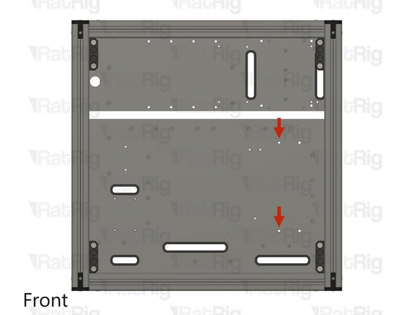
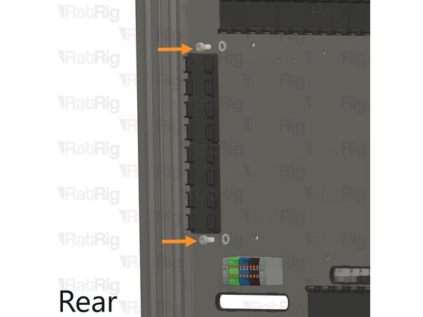
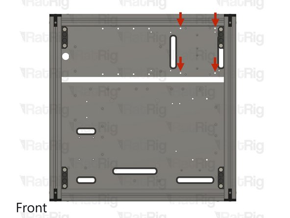
Install the component using the designated holes.
-
2x M4x8 Cap Head Screw + M4 Washer
-
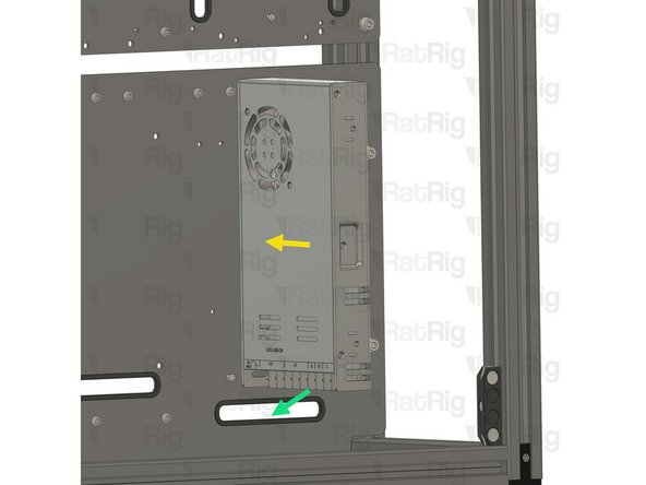
Power Supply Weho - 350Watt 24V
-
Install the power supply as illustrated, securing it by screwing the M4 screw into the threaded holes on the side of the power supply body.
-
Feed all the wires through the designated slot.
-
The AC wires will be connected in another guide.
-
-
-
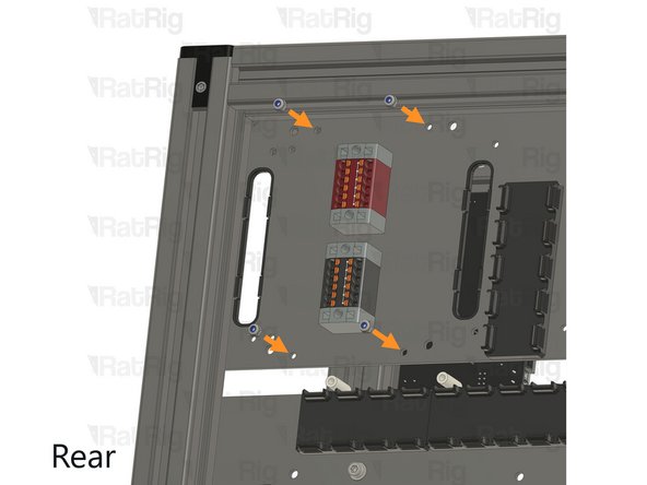
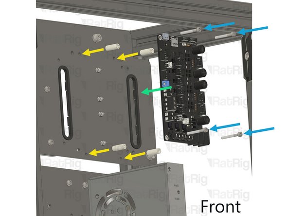
Install the component using the designated holes.
-
4x Hex Locking Nut - M3
-
4x Nylon Spacer - 3.2x6x16mm
-
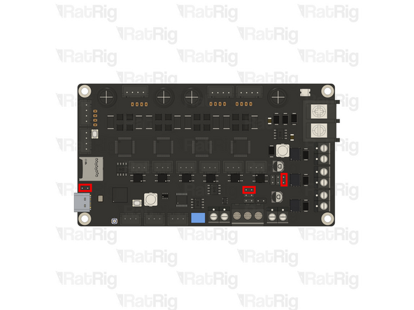
BigTreeTech & Rat Rig - Rodent CNC Controller TMC2160
-
4x M3x25 Cap Head Screw
-
Insert the M3x25 cap head screws through the rodent and nylon spacers, then through the designated holes on the plate. Finally, secure them by fastening to the M3 hex locking nuts on the back.
-
-
-
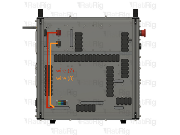
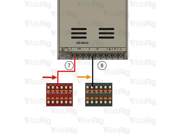
600mm - 16AWG RED (A-Fork, B-Ferrule) (7)
-
Wire (7) should be attached to the power supply 02. Common components . Route it as shown and connect the ferrule end to the +24V RED PTFix terminal.
-
600mm - 16AWG BLACK (A-Fork, B-Ferrule) (8)
-
Wire (8) should be attached to the power supply 02. Common components . Route it as shown and connect the ferrule end to the -24V BLACK PTFix terminal.
-
After insertion, attempt to pull the wire to verify that it is securely attached.
-
-
-
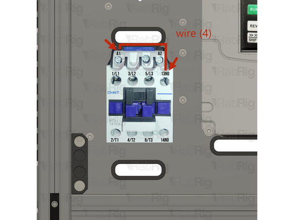
120mm - 16AWG RED (A-Fork, B-Fork) (4)
-
Insert wire (4) in the 13NO terminal on the contactor and connect it to the A1 terminal of the contactor.
-
After insertion, attempt to pull the wire to verify that it is securely attached.
-
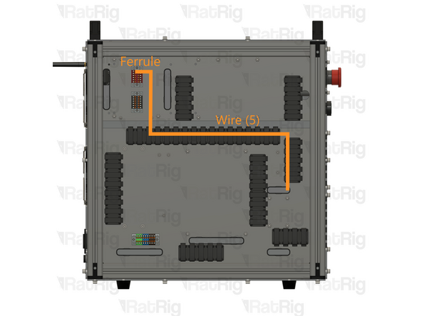
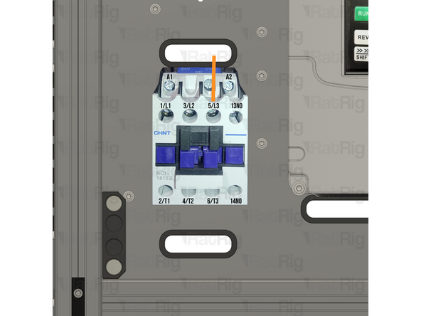
800mm - 16AWG RED (A-Fork, B-Ferrule) (5)
-
Insert wire (5) in the 5/L3 terminal on the contactor and connect it to the +24V Red PTFix block.
-
-
-
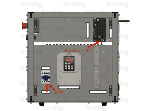
800mm - 16AWG RED (A-Fork, B-Fork) (6)
-
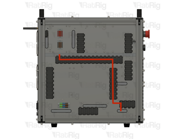
Route the wire as shown.
-
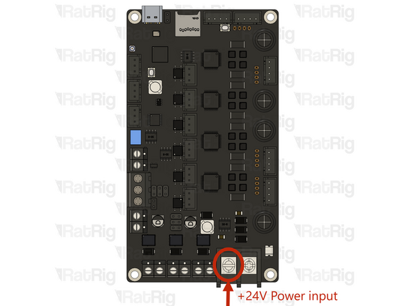
Insert wire (6) in the 6/T3 terminal on the contactor and connect it to the +24V Rodent input.
-
After insertion, attempt to pull the wire to verify that it is securely attached.
-
-
-
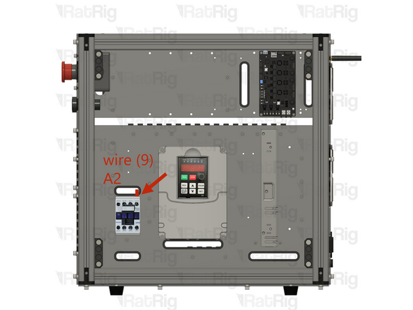
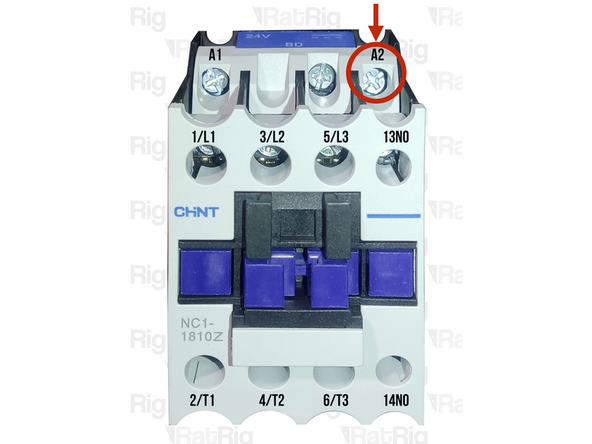
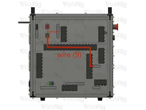
700mm - 16AWG BLACK (A-Fork, B-Ferrule) (9)
-
Insert wire (9) in the A2 terminal on the contactor and connect it to the -24V Black PTFix with the ferrule.
-
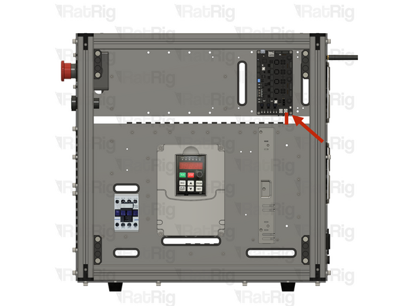
Route the wire as shown.
-
After insertion, attempt to pull the wire to verify that it is securely attached.
-
-
-
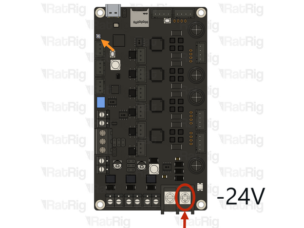
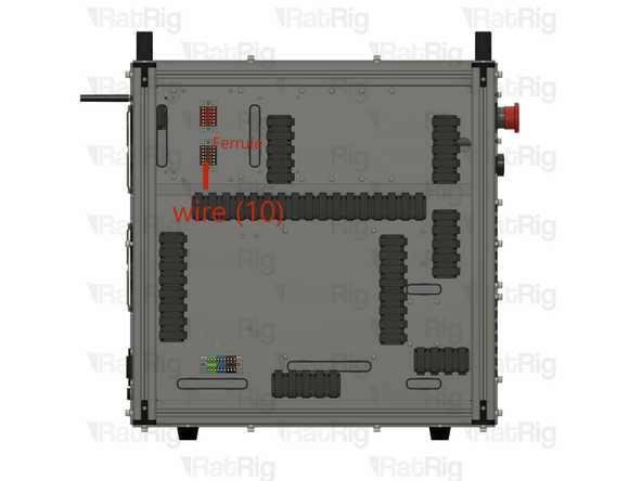
100mm - 16AWG BLACK (A-Fork, B-Ferrule) (10)
-
Insert wire (10) on the -24V Black PTFix with the ferrule and connect it to the -24V Rodent input.
-
Route the wire as shown.
-
After insertion, attempt to pull the wire to verify that it is securely attached.
-
Connect the Wifi antenna wire to the rodent
-
-
-
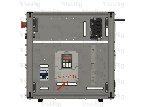
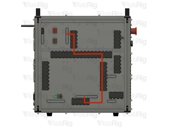
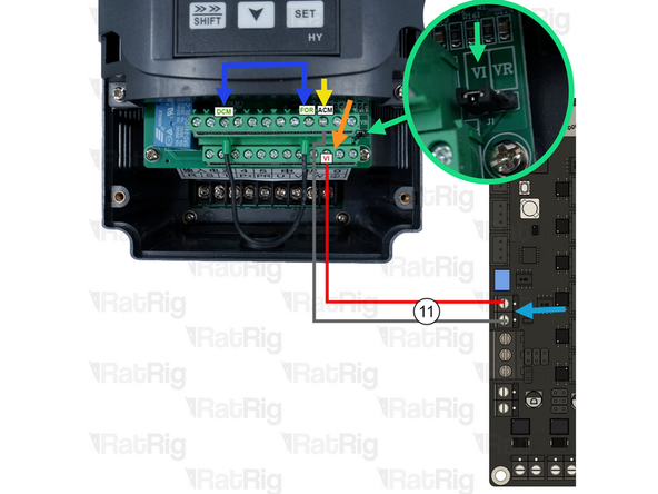
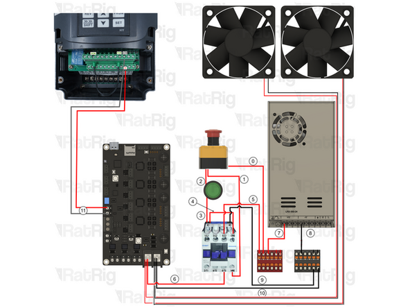
900mm - Multicore 2 Conductor - 24AWG (A-2xFerrule, B-2xFerrule) (11)
-
Connect the Red wire to the VI input on the VFD.
-
Connect the Black wire to the ACM input on the VFD
-
Ensure the VI jumper is set as shown.
-
Connect the Red and Black ferrules as to the Rodent output as shown.
-
Ensure the VFD Jumper wire is set between the ACM and FOR terminals.
-
-
-
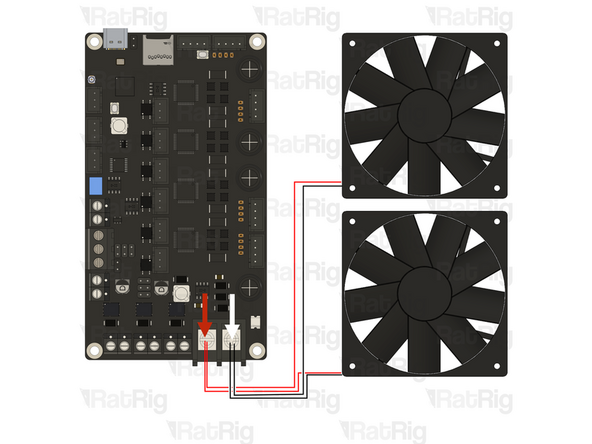
Cut the JST connectors on the cooling fans and crimp both red wires in the same ferrule, then insert it into the left power terminal of the rodent controller.
-
Cut the JST connectors on the cooling fans and crimp both black wires in the same ferrule, then insert it into the right power terminal of the rodent controller.
-
-
-
Take your time to double-check all the connections previously made.
-