
-
-
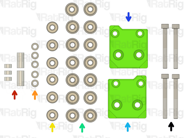
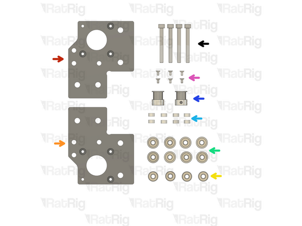
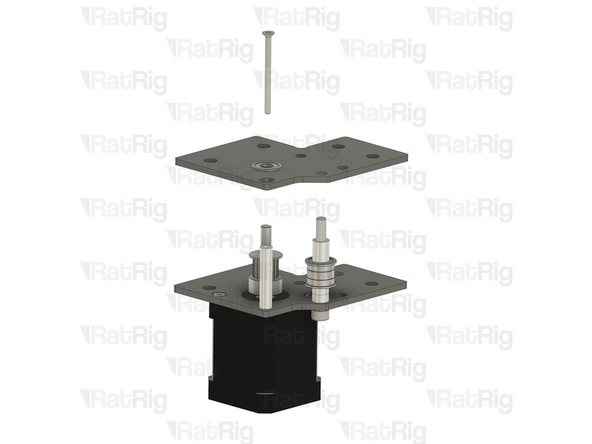
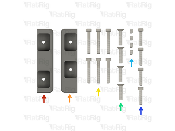
Right Stepper motor plate assembly from Step 28 of chapter 01.Frame assembly
-
Left Stepper motor plate assembly from Step 28 of chapter 01.Frame assembly
-
2x Nema 17 Stepper motor - HT - 48mm
-
2x 20 Tooth 2GT Timing Pulley for 9mm Belt
-
6x M3x6 Countersink Screws
-
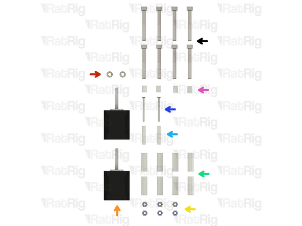
2x M5x85 Cap Head Screws
-
-
-
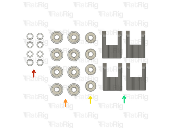
3x Aluminium spacer 5x8x4mm + 1x Aluminium spacer 5x8x14mm + Aluminium spacer 5x8x17mm
-
5x Mini precision shim 8x5x1mm
-
6x Ball bearing 695ZZ
-
14x Ball bearing F695ZZ
-
Right vc4_motor_spacer
-
Left vc4_motor_spacer
-
4x M5x45 Cap Head Screws
-
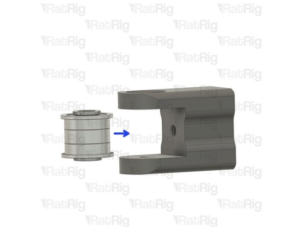
6x Heavy-Duty Idler – The latest V-Core 4 kits now feature these heavy-duty idlers as a replacement for the previously used bearing stack assemblies.
-
-
-
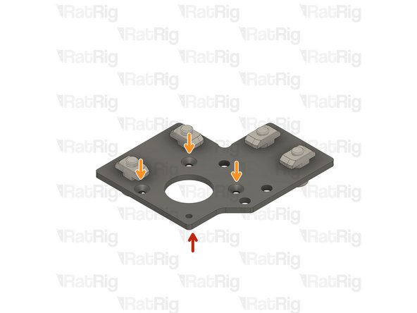
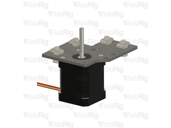
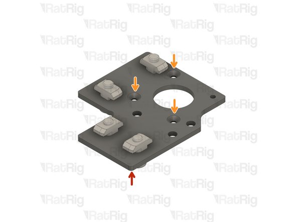
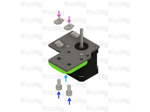
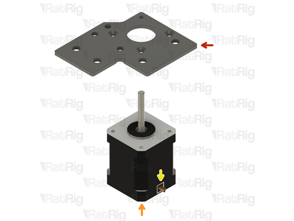
Right Stepper motor plate assembly from Step 28 of chapter 01.Frame assembly
-
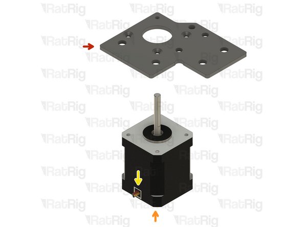
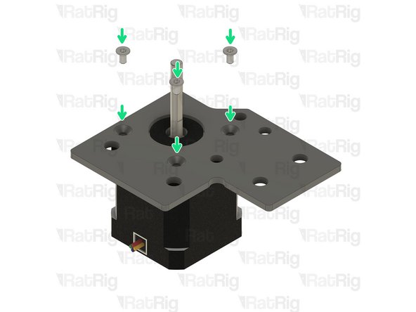
Ensure the t-nuts are on the same side as the countersink bores.
-
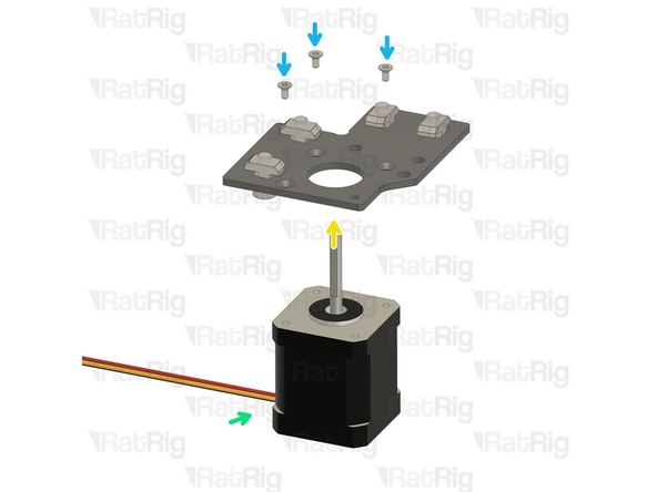
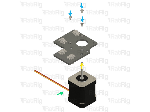
Nema 17 Stepper motor - HT - 48mm
-
Make sure the cable from the stepper motor faces the direction shown in the image
-
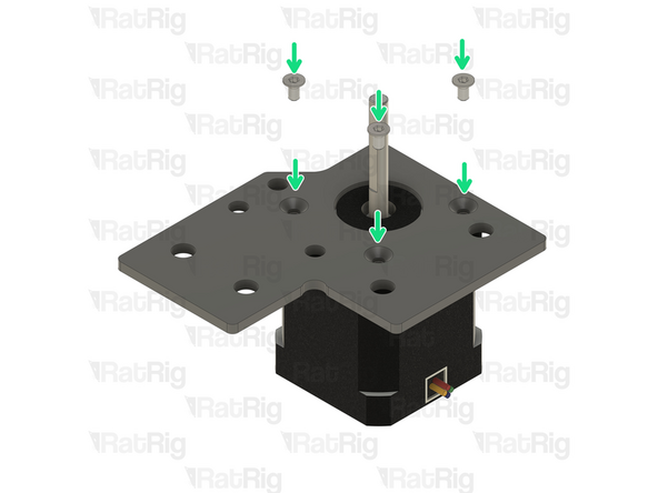
3x M3x6 Countersink Screws
-
Insert the M3x6 screws into the Right Stepper motor plate assembly as shown, and fasten them to secure the NEMA17 motor.
-
-
-
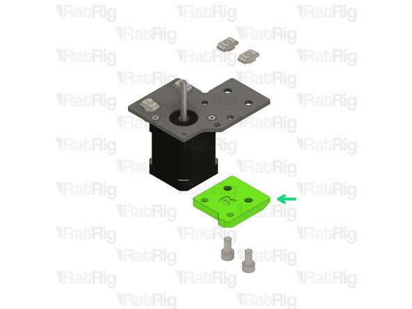
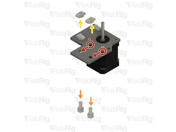
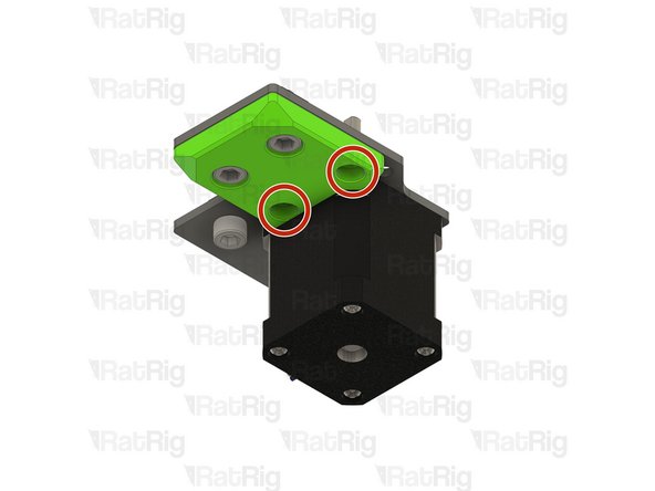
Refer to the side of the assembly which has the M5 holes
-
Remove the two M6x12 Cap Head Screws
-
Remove the two 3030 Drop-in T-Nut - M6
-
Right vc4_motor_spacer
-
Install the printed part next to the nema 17 stepper motors, and make sure the holes are aligned.
-
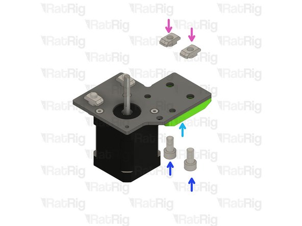
Insert the two M6x12 Cap Head Screws
-
Insert the two 3030 Drop-in T-Nut - M6
-
Loosely thread a 3030 T-Nut onto each of the M6x12 screws. Do not tighten them at this point.
-
-
-
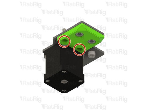
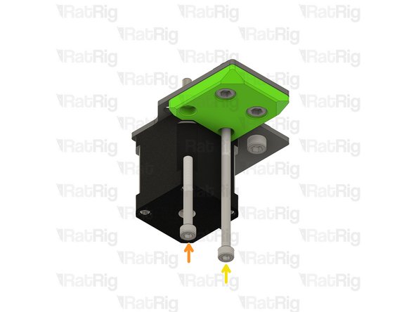
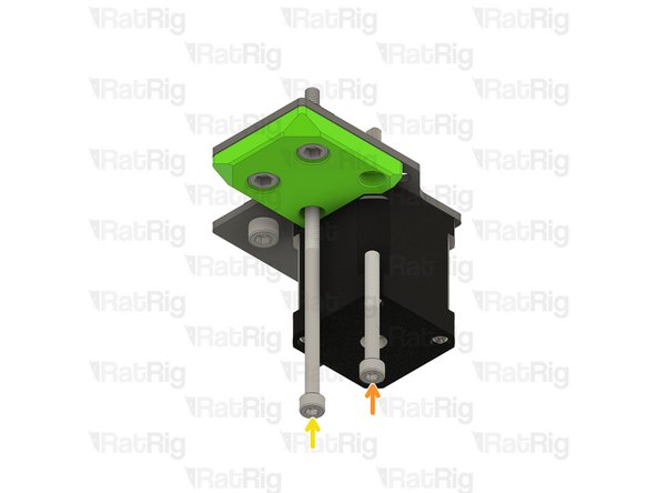
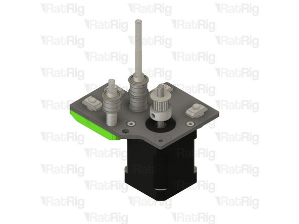
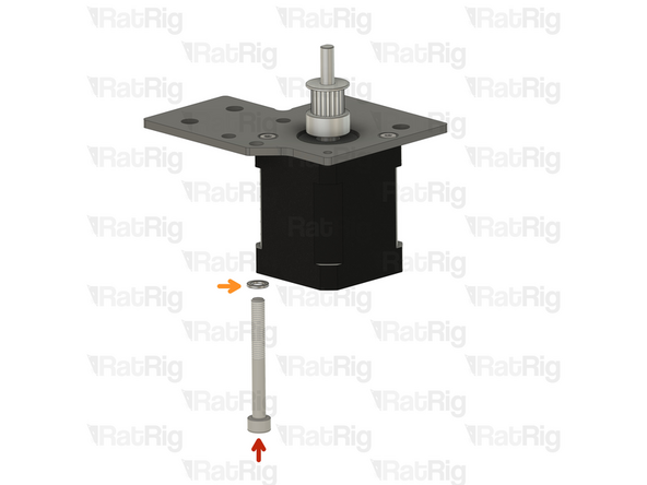
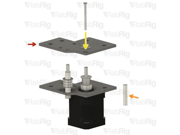
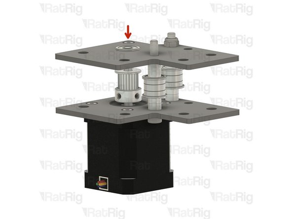
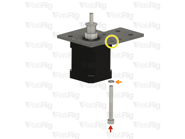
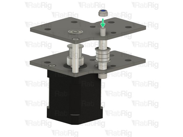
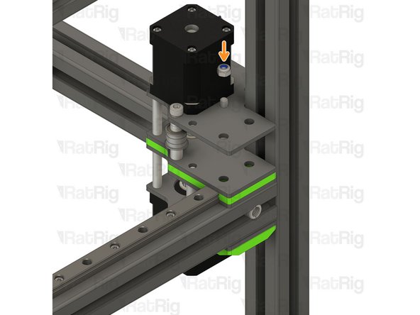
Ensure the right vc4_motor_spacer printed part is aligned with the plate
-
Insert the M5x45 Cap Head Screw all the way
-
Insert the M5x85 Cap Head Screw all the way
-
Once inserted, the printed part should be able to hold them in place
-
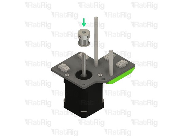
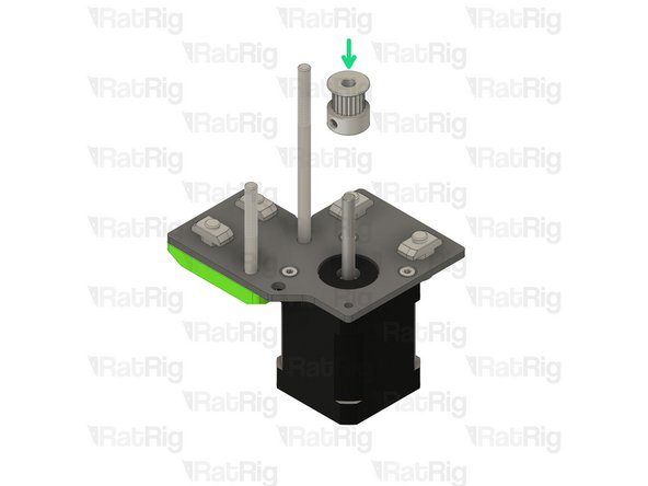
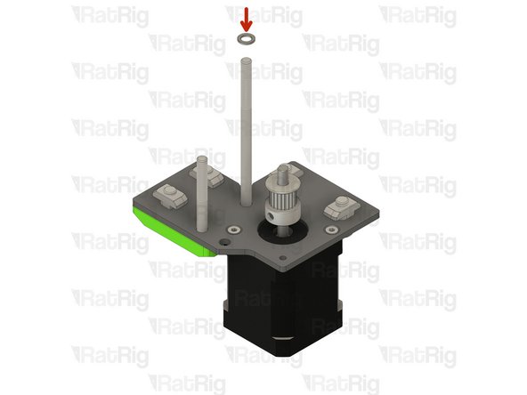
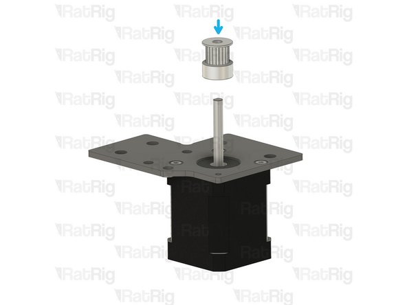
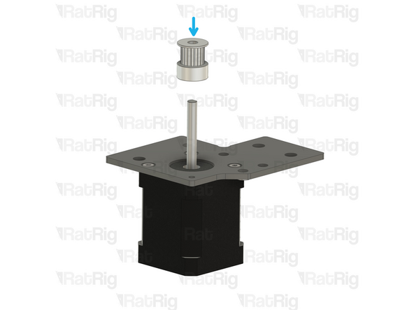
Install the timing pulley onto the NEMA17 shaft, oriented as shown
-
The timing pulley will be aligned and fully secured in a later step. Do not tighten the M3 grub screws
-
-
-
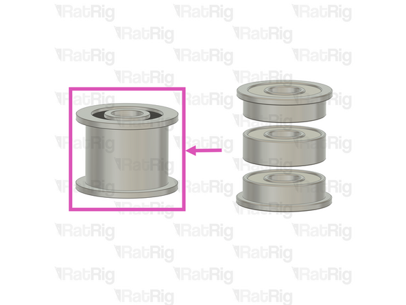
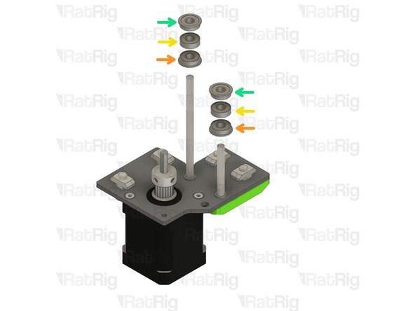
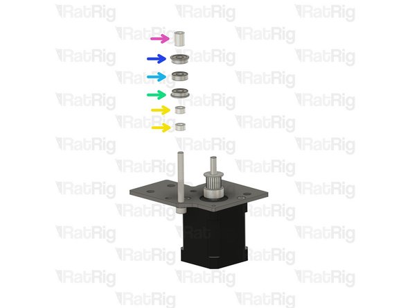
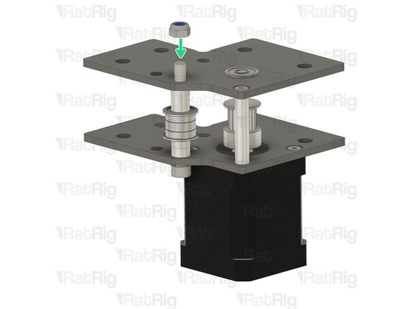
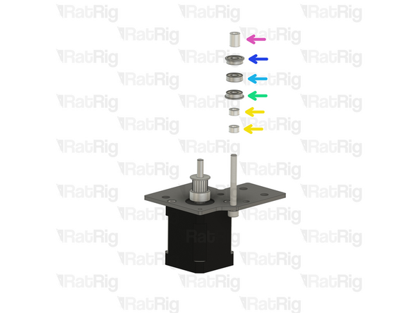
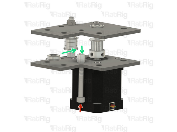
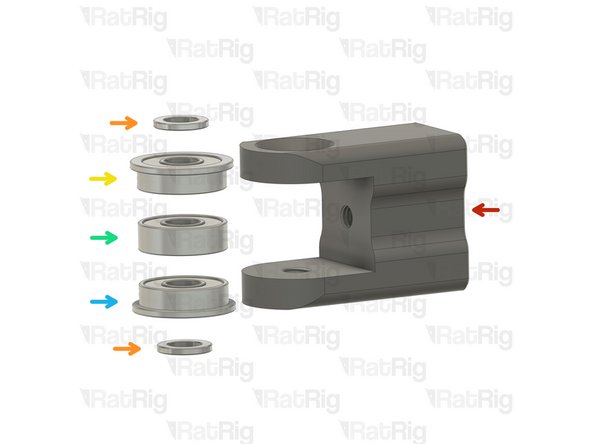
Install the following components in the order shown in the image:
-
Mini Precision Shim
-
F695ZZ Ball Bearing (Flange at the bottom)
-
695ZZ Ball Bearing
-
F695ZZ Ball Bearing (Flange at the top)
-
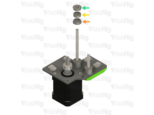
If you purchased the heavy duty idler pulleys, replace each ball bearings stack shown with a heavy duty idler pulley. This applies throughout the build.
-
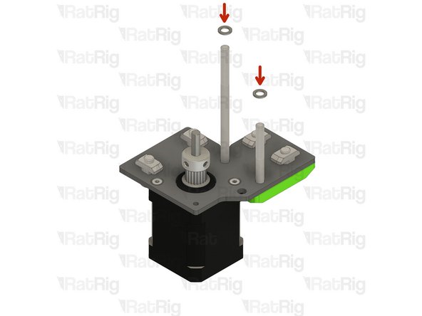
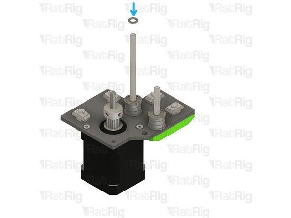
Insert a Mini Precision Shim on the rear M5x85 Screw
-
-
-
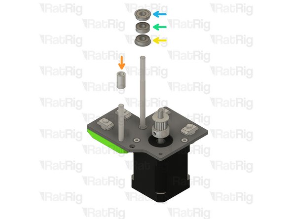
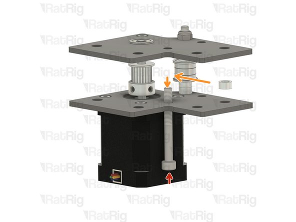
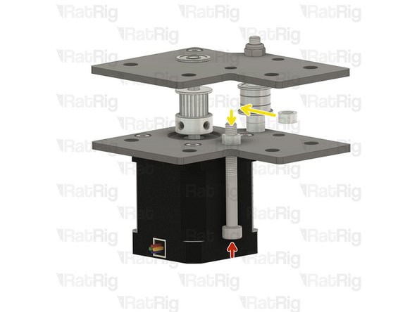
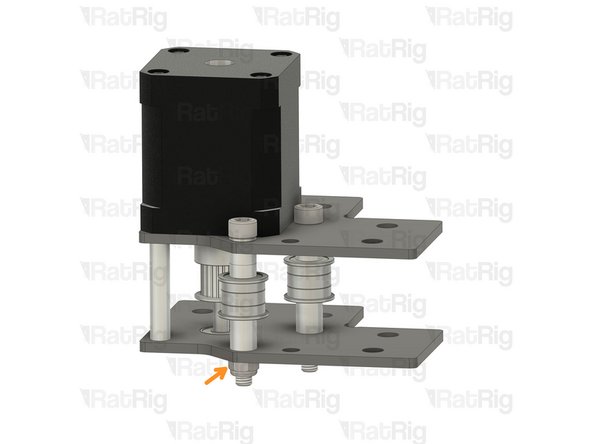
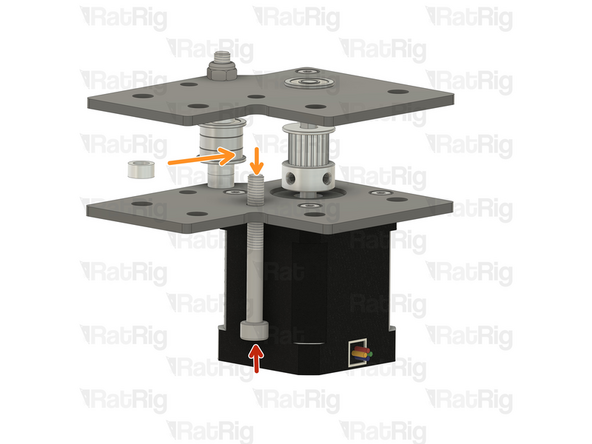
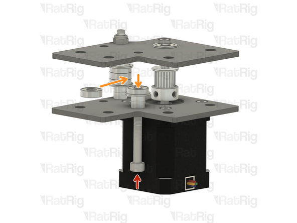
Install the following components on the rear M5x85 Screw in the order shown in the image:
-
F695ZZ Ball Bearing (Flange at the bottom)
-
695ZZ Ball Bearing
-
F695ZZ Ball Bearing (Flange at the top)
-
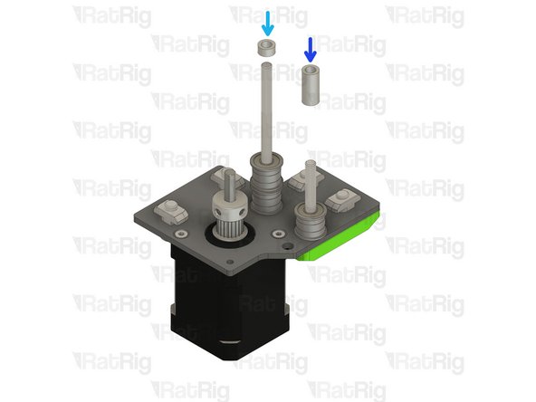
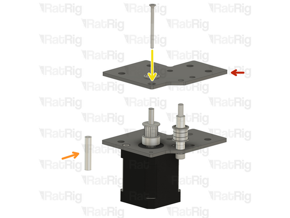
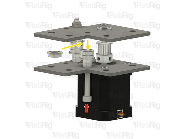
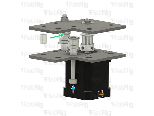
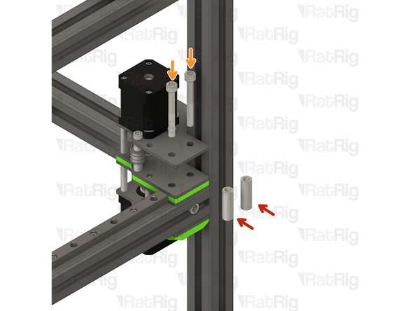
Install an Aluminium spacer 5x8x4mm on the rear M5x85 Screw
-
Install an Aluminium spacer 5x8x17mm on the front M5x45 Screw
-
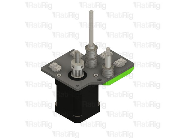
Set the assembly aside, let's assemble the left stepper motor.
-
-
-
Left Stepper motor plate assembly from Step 28 of chapter 01.Frame assembly
-
Ensure the t-nuts are on the same side as the countersink bores.
-
Nema 17 Stepper motor - HT - 48mm
-
Make sure the cable from the stepper motor faces the direction shown in the image
-
3x M3x6 Countersink Screws
-
Insert the M3x6 screws into the Left Stepper motor plate assembly as shown, and fasten them to secure the NEMA17 motor.
-
-
-
Refer to the side of the assembly which has the M5 holes
-
Remove the two M6x12 Cap Head Screws
-
Remove the two 3030 Drop-in T-Nut - M6
-
Left vc4_motor_spacer
-
Install the printed part next to the nema 17 stepper motors, and make sure the holes are aligned.
-
Insert the two M6x12 Cap Head Screws
-
Insert the two 3030 Drop-in T-Nut - M6
-
Loosely thread a 3030 T-Nut onto each of the M6x12 screws. Do not tighten them at this point.
-
-
-
Ensure the left vc4_motor_spacer printed part is aligned with the plate
-
Insert the M5x45 Cap Head Screws all the way
-
Insert the M5x85 Cap Head Screws all the way
-
Once inserted, the printed part should be able to hold them in place
-
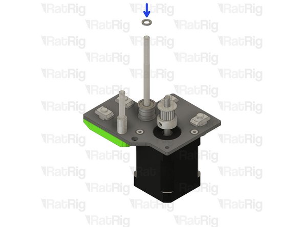
Install the timing pulley onto the NEMA17 shaft, oriented as shown
-
The timing pulley will be aligned and fully secured in a later step. Do not tighten the M3 grub screws
-
-
-
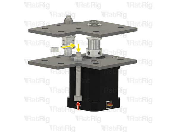
Insert a Mini Precision Shim on the rear M5x85 Screw
-
Install an Aluminium spacer 5x8x14mm on the front M5x45 Screw
-
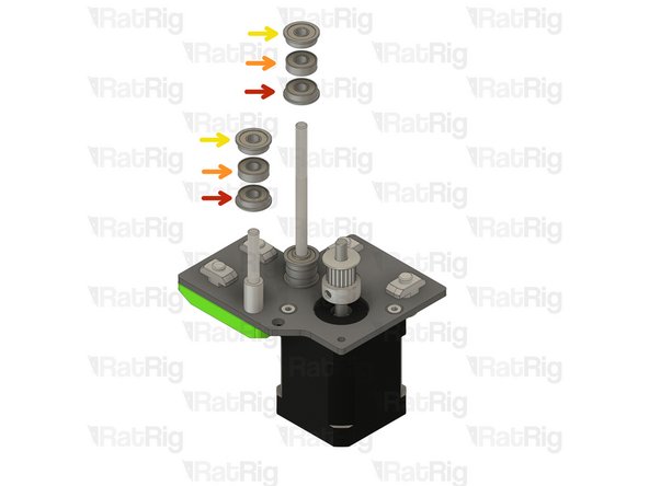
Install the following components on the rear M5x85 Screw in the order shown in the image:
-
F695ZZ Ball Bearing (Flange at the bottom)
-
695ZZ Ball Bearing
-
F695ZZ Ball Bearing (Flange at the top)
-
Insert a Mini Precision Shim on the rear M5x85 Screw
-
-
-
Install the following components in the order shown in the image:
-
F695ZZ Ball Bearing (Flange at the bottom)
-
695ZZ Ball Bearing
-
F695ZZ Ball Bearing (Flange at the top)
-
Aluminium spacer 5x8x4mm
-
Set the assembly aside, it will be used in a few steps
-
-
-
2x vc4_xy_motor_upper_ right
-
2x vc4_xy_motor_upper_ left
-
2x vc4_dual_motor_motor_spacer
-
4x F695ZZ Bearing
-
4x M5 Nylon Locking Nut
-
4x M3x40 Countersink Screws
-
4x Aluminium Spacer 3x6x30mm
-
8x 3030 Drop-in T-Nut - M6
-
-
-
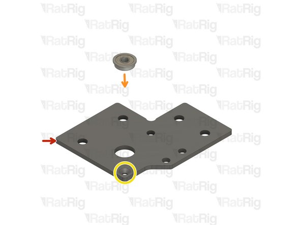
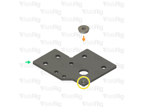
vc4_xy_motor_upper_right
-
Ball bearing F695ZZ
-
Ensure the bearing flange is on the same side as the countersink bore.
-
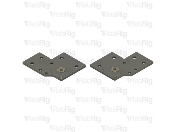
vc4_xy_motor_upper_left
-
Repeat the previous steps and assemble the upper left plate
-
-
-
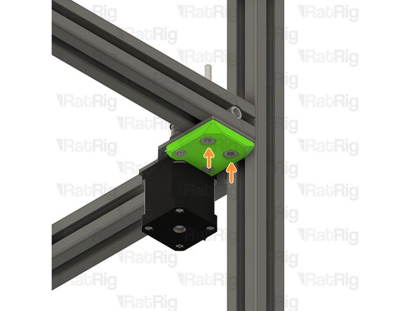
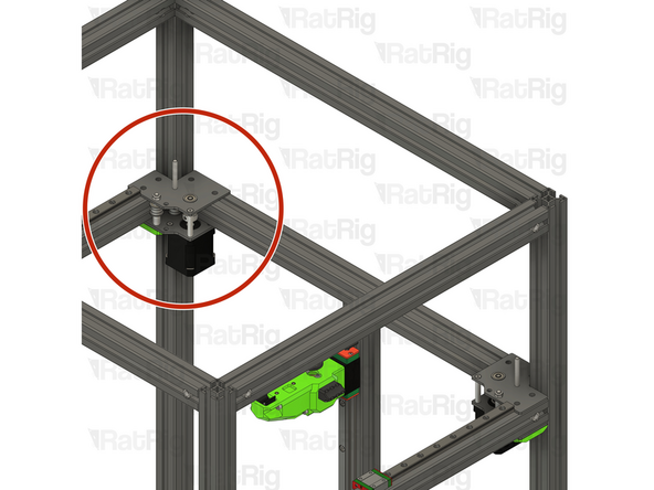
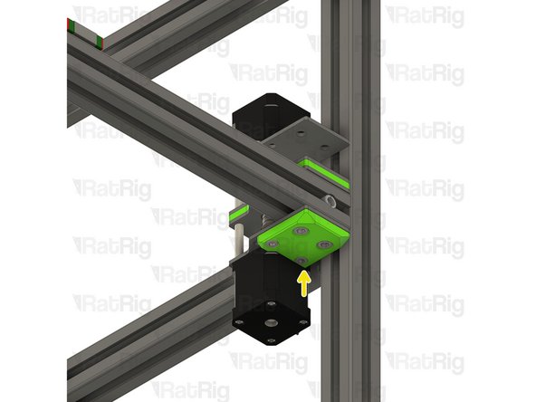
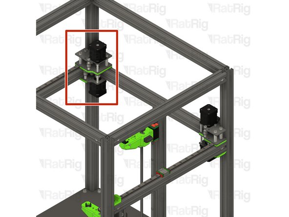
Place the right stepper motor assembly from Step 12 in the frame.
-
Make sure the plate is fully seated against the 3030 extrusion before the next step.
-
-
-
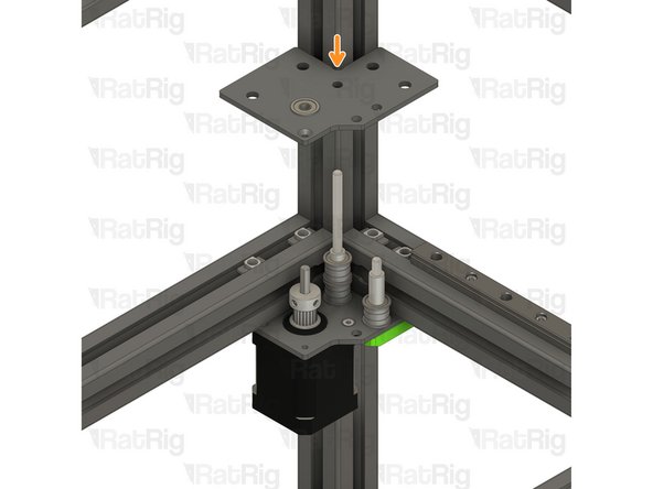
Tighten the four M6x12 screws to secure the motor plate assembly to the frame
-
Take care not to over tighten the M6x12 screws as you can damage the printed parts
-
-
-
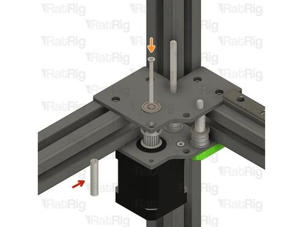
4x 3030 Drop-in T-Nut - M6
-
Insert the T-Nuts inside the profile in the shown orientation.
-
Upper right plate assembly from Step 14
-
Make sure the Stepper motor shaft is aligned with the F695ZZ Bearing inner hole.
-
-
-
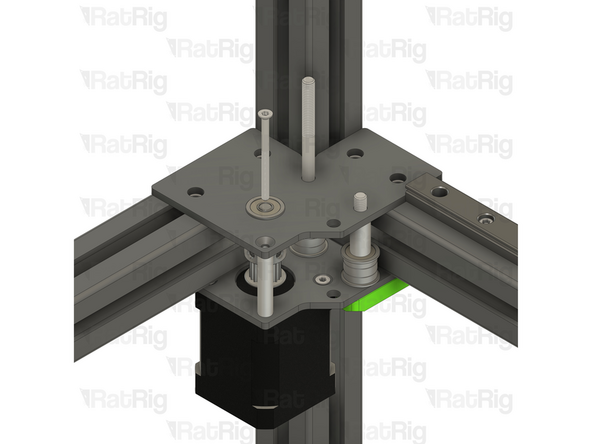
Insert the Aluminium Spacer 3x6x30mm between the top and bottom plates
-
Insert the M3x40 countersink screw through the top plate, the aluminium spacer 3x6x30mm, and the bottom plate.
-
Do not thread it to the stepper motor at this stage
-
M5 Hex Locking nut
-
Thread the locking nut in the M5x45mm Cap Head Screw
-
-
-
Hold the Locking nut with the appropriate size wrench.
-
Tighten the M5x45mm Cap Head Screw
-
Ensure the bearings rotate freely.
-
Tighten the M3x40 Countersink Screw
-
-
-
Repeat Steps 15 to 19 and install the left stepper motor to the V-Core 4 frame.
-
-
-
1x vc4_xy_motor_lower_right
-
1x vc4_xy_motor_lower_left
-
4x 695ZZ Bearing
-
8x F695ZZ Bearing
-
8x Aluminium Spacer 5x8x4mm
-
2x 20 Tooth 2GT Timing Pulley for 9mm Belt
-
6x M3x6 Countersink Screw
-
4x M5x45 Cap Head Screw
-
-
-
2x Mini precision shim 8x5x1mm
-
2x Nema 17 Stepper motor - HT - 48mm
-
6x M5 Hex Locking nut
-
8x Aluminium Spacer 6x10x30mm
-
2x Aluminium Spacer 3x6x30
-
2x M3x40 CounterSink Screw
-
4x Aluminium Spacer 5x8x10mm
-
8x M6x50 Cap Head Screw
-
-
-
vc4_XY_motor_lower_left
-
Nema 17 Stepper motor - HT - 48mm
-
Be mindful of the cable orientation.
-
3x M3x6 Countersink Screws
-
Insert the M3x6 screws into the Right Stepper motor plate assembly as shown, and fasten them to secure the NEMA17 motor.
-
20 Tooth 2GT Timing Pulley for 9mm Belt
-
The timing pulley will be aligned and fully secured when needed. Do not tighten the M3 grub screws
-
-
-
M5x45 Cap Head Screw
-
Insert a mini precision shim on the screw, before installing it on the plate.
-
Install the following components in the order shown in the image:
-
2x Aluminium spacer 5x8x4mm
-
F695ZZ Ball Bearing (Flange at the bottom)
-
695ZZ Ball Bearing
-
F695ZZ Ball Bearing (Flange at the top)
-
Aluminium spacer 5x8x10mm
-
-
-
vc4_xy_motor_upper_right
-
Aluminium Spacer 3x6x30mm
-
Insert the Aluminium Spacer between the top and bottom plates
-
M3x40 Countersink Screw
-
Insert the M3x40 countersink screw through the top plate, the aluminium spacer 3x6x30mm, and the bottom plate. Loosely thread it onto the stepper motor. Do not tighten them at this point.
-
Ensure the screw head is on the same side as the countersink bore.
-
M5 Nylon Locking Nut
-
Thread the locking nut on to the M5x45 Cap Head Screw
-
-
-
M5x45 Cap Head Screw
-
Insert it in the designated hole and push it in 5-10mm
-
Insert the following items while pushing the M5x45 Cap head screw further:
-
Aluminium spacer 5x8x4mm
-
Insert the M5x45 further
-
Aluminium spacer 5x8x4mm
-
Insert the M5x45 further
-
F695ZZ Ball Bearing (Flange at the bottom)
-
-
-
Insert the following items while pushing the M5x45 Cap head screw further:
-
695ZZ Ball Bearing
-
Insert the M5x45 further
-
F695ZZ Ball Bearing (Flange at the top)
-
Insert the Aluminium spacer 5x8x10mm
-
Fully insert the M5x45mm Cap Head Screw
-
Don't allow it to drop!
-
-
-
Flip the assembly upside down, ensuring the M5x45 Cap Head Screw can't fall.
-
Tighten the M3 countersink screw
-
Tighten the M5 nylon locking nut
-
Put the assembly aside, it will be used later in the guide.
-
-
-
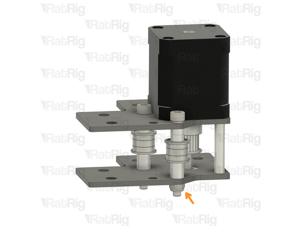
vc4_XY_motor_lower_right
-
Nema 17 Stepper motor - HT - 48mm
-
Be mindful of the cable orientation.
-
3x M3x6 Countersink Screws
-
Insert the M3x6 screws into the Right Stepper motor plate assembly as shown, and fasten them to secure the NEMA17 motor.
-
20 Tooth 2GT Timing Pulley for 9mm Belt
-
The timing pulley will be aligned and fully secured in a later step. Do not tighten the M3 grub screws
-
-
-
M5x45 Cap Head Screw
-
Insert a mini precision shim on the screw, before installing it on the plate.
-
Install the following components in the order shown in the image:
-
2x Aluminium spacer 5x8x4mm
-
F695ZZ Ball Bearing (Flange at the bottom)
-
695ZZ Ball Bearing
-
F695ZZ Ball Bearing (Flange at the top)
-
Aluminium spacer 5x8x10mm
-
-
-
vc4_xy_motor_upper_left
-
Aluminium Spacer 3x6x30mm
-
Insert the Aluminium Spacer between the top and bottom plates
-
M3x40 Countersink Screw
-
Insert the M3x40 countersink screw through the top plate, the aluminium spacer 3x6x30mm, and the bottom plate. Loosely thread it onto the stepper motor. Do not tighten them at this point.
-
Ensure the screw head is on the same side as the countersink bore.
-
M5 Nylon Locking Nut
-
Thread the locking nut on to the M5x45 Cap Head Screw
-
-
-
M5x45 Cap Head Screw
-
Insert it in the designated hole and push it in 5-10mm
-
Insert the following items while pushing the M5x45 Cap head screw further:
-
Aluminium spacer 5x8x4mm
-
Insert the M5x45 further
-
Aluminium spacer 5x8x4mm
-
Insert the M5x45 further
-
F695ZZ Ball Bearing (Flange at the bottom)
-
-
-
Insert the following items while pushing the M5x45 Cap head screw further:
-
695ZZ Ball Bearing
-
Insert the M5x45 further
-
F695ZZ Ball Bearing (Flange at the top)
-
Insert the Aluminium spacer 5x8x10mm
-
Fully insert the M5x45mm Cap Head Screw
-
Don't allow it to drop!
-
-
-
Flip the assembly upside down, ensuring the M5x45 Cap Head Screw can't fall.
-
Tighten the M3 countersink screw
-
Tighten the M5 nylon locking nut
-
Put the assembly aside, it will be used later in the guide.
-
-
-
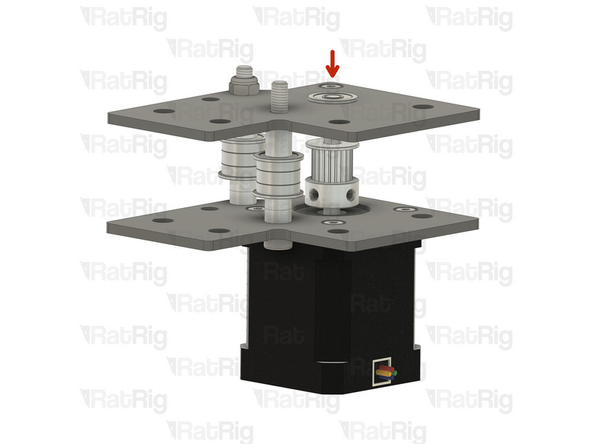
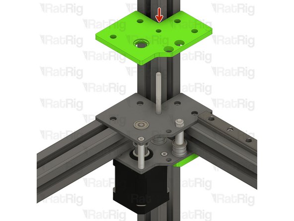
vc4_dual_motor_spacer
-
Insert the printed part through the screws.
-
Ensure the t-nuts are aligned with the printed part holes, this will be critical in the next steps. You can use a small allen key to help align them
-
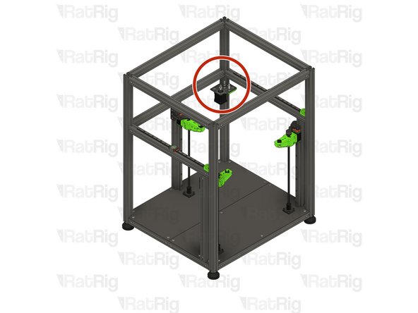
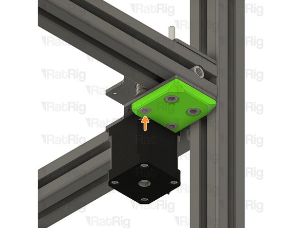
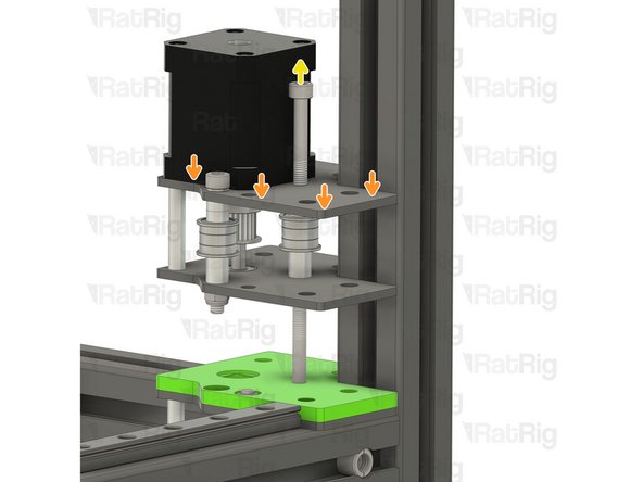
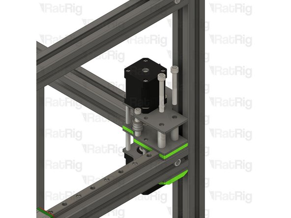
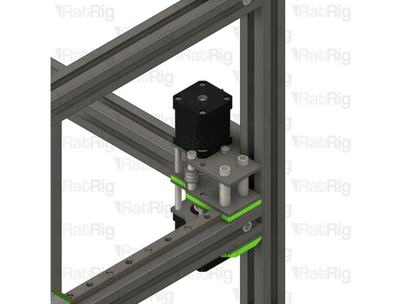
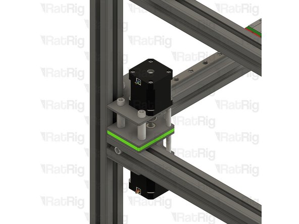
Upper right Y motor assembly from Step 28
-
Make sure the assembly is flush with the frame extrusion before proceeding.
-
-
-
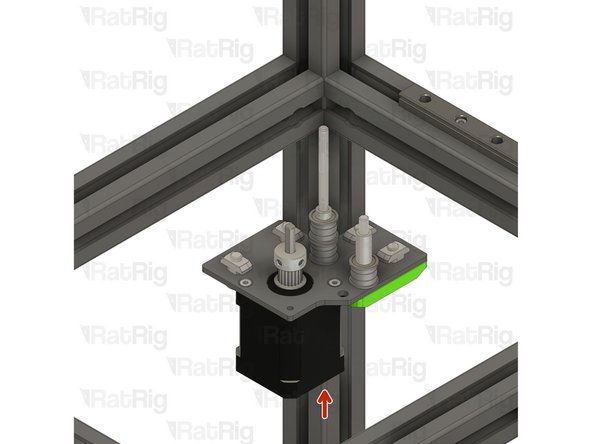
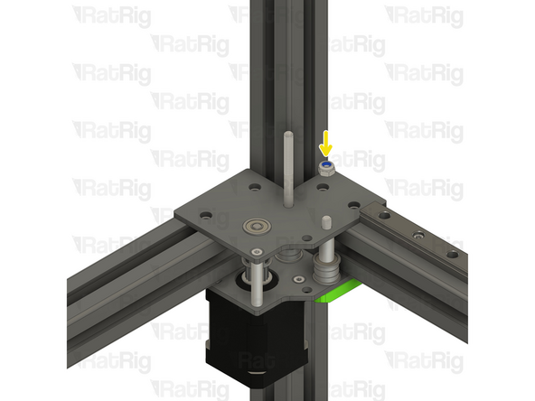
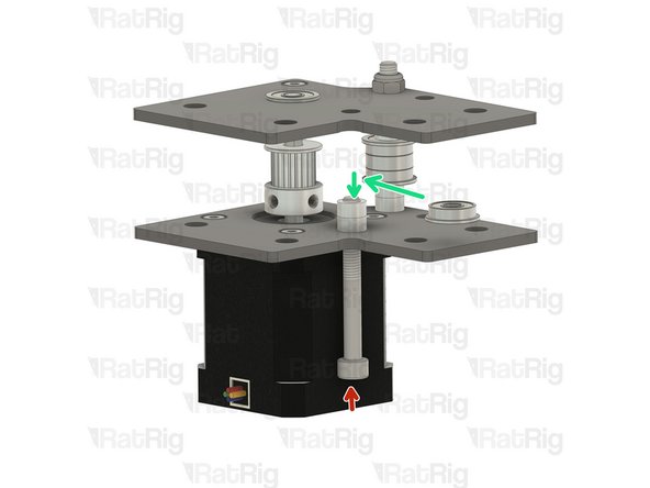
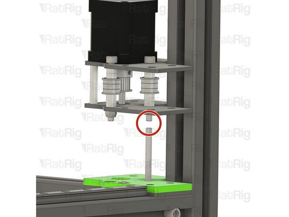
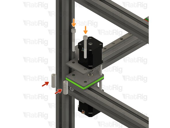
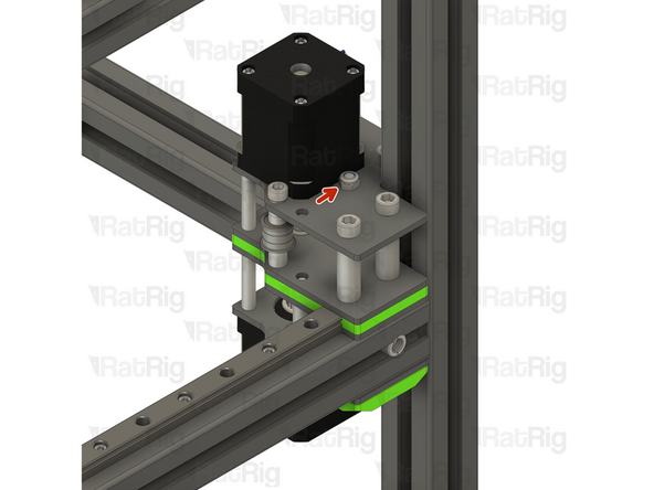
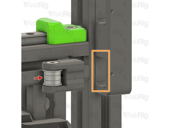
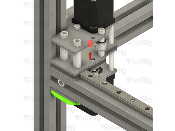
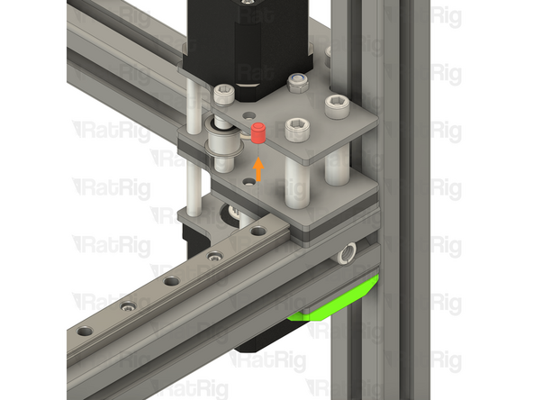
Align the M5x85 Cap Head Screw already on the V-Core 4, with the M5x45 Cap Head Screw on the Top Y stepper assembly
-
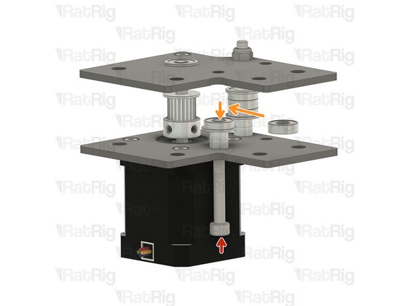
Slowly drop the Top Y stepper assembly
-
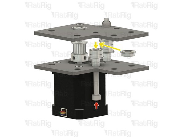
While allowing the M5x85 Screw to push the M5x45 Screw out.
-
Take it slowly, as it's crucial that all components get transferred to the M5x85 Cap Head Screw
-
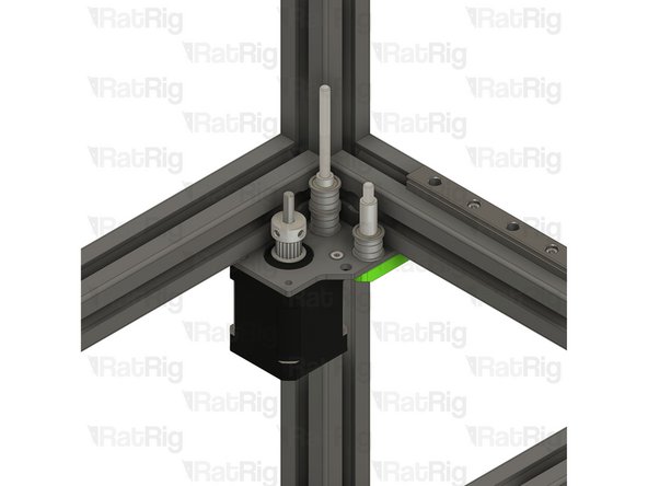
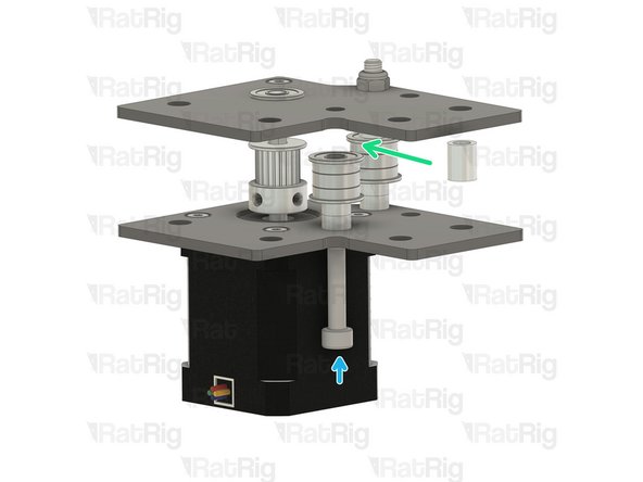
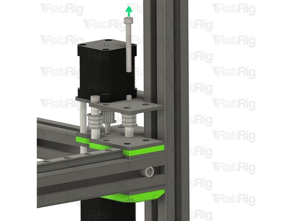
Completely remove the M5x45 Cap Head Screw, it won't be used anymore.
-
Store it in the "upcoming project spare parts box"
-
-
-
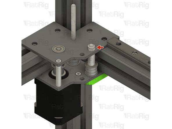
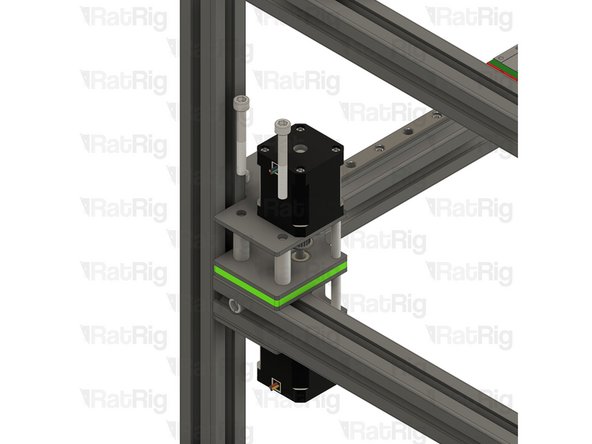
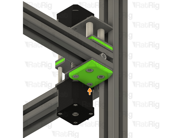
Make sure the Top Y Stepper assembly is fully seated on the printed part
-
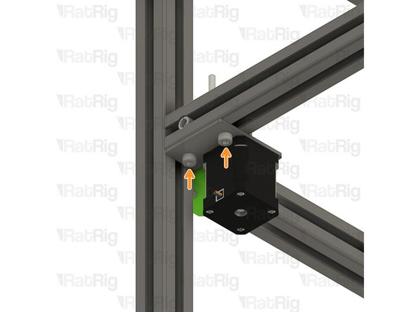
M5 Nylon Locking Nut
-
Hold the Locking nut with the appropriate size wrench.
-
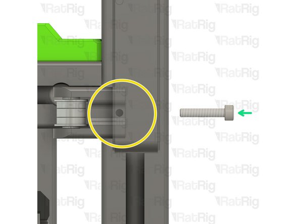
Thread the M5x85 Cap Head Screw in to the M5 Nylon Locking Nut
-
Do not fully tighten it yet, it will be addressed further in the guide.
-
-
-
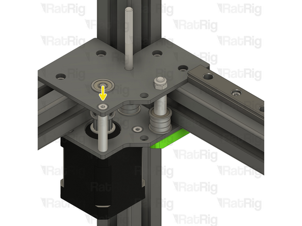
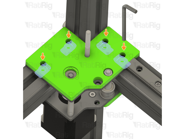
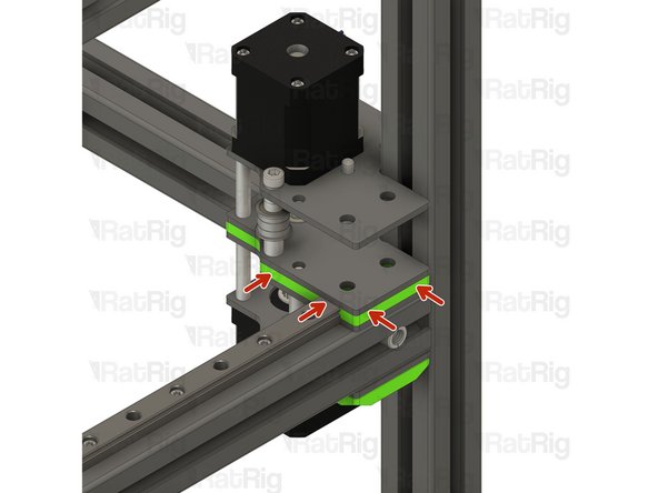
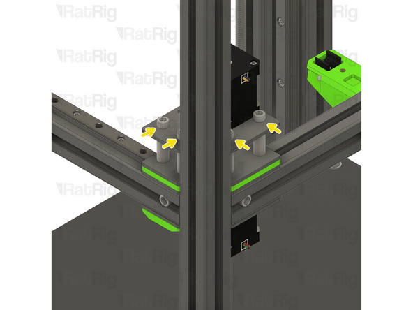
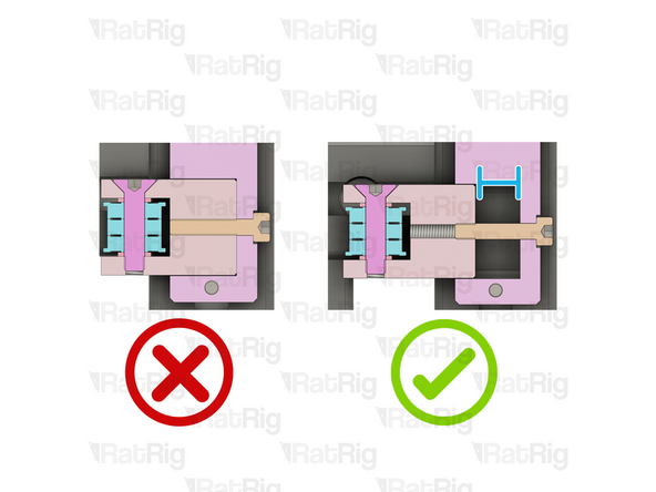
Verify that all T-nuts are aligned with the holes on the Top Y Stepper assembly.
-
Use a small allen key, or a screw if any t-nut is misaligned.
-
-
-
2x Aluminium Spacer 6x10x30mm
-
Insert the spacer between the plates and align it with the holes
-
2x M6x50 Cap Head Screws
-
Insert the screws through the top plate, spacers and bottom plate, threading them into the previously inserted M6 T-nuts. Do not fully tighten them yet
-
-
-
2x Aluminium Spacer 6x10x30mm
-
Insert the spacer between the plates and align it with the holes
-
2x M6x50 Cap Head Screws
-
Insert the screws through the top plate, spacers and bottom plate, threading them into the previously inserted M6 T-nuts. Do not fully tighten them yet
-
-
-
Hold the Locking nut with the appropriate size wrench.
-
Tighten the M5x85 Cap Head Screw
-
Ensure the bearings rotate freely.
-
Tighten all the M6x50 to secure the assembly
-
-
-
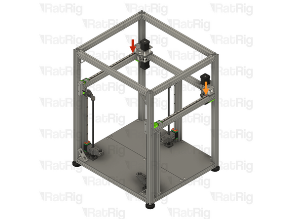
Repeat Steps 35 to 41 and install the upper left Y motor assembly from Step 34 on the V-Core 4 frame.
-
-
-
Rat Rig V-Core 4.0 - Tensioner Body - Right v1.0
-
Rat Rig V-Core 4.0 - Tensioner Body - Left v1.0
-
6x M4x30 Cap Head Screw
-
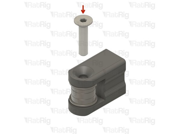
4x M5x22 Countersink Screw
-
4x M4x6 Set Screw
-
4x M4x20 Cap Head Screw
-
-
-
8x Mini precision shim 8x5x1mm
-
8x Ball bearing F695ZZ
-
4x Ball bearing 695ZZ
-
4x Rat Rig V-Core 4.0 - Tensioner Arm v1.0
-
4x Heavy-Duty Idler – The latest V-Core 4 kits now feature these heavy-duty idlers as a replacement for the previously used bearing stack assemblies.
-
-
-
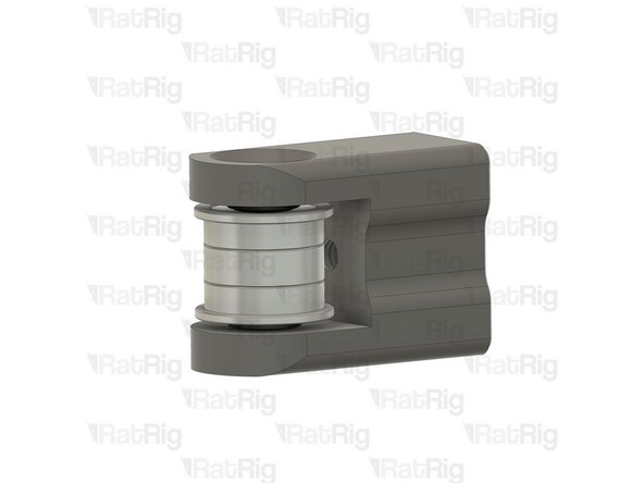
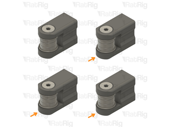
Rat Rig V-Core 4.0 - Tensioner Arm v1.0
-
Install the following components in the order shown in the image:
-
Mini Precision Shim
-
F695ZZ Ball Bearing (Flange at the top)
-
695ZZ Ball Bearing
-
F695ZZ Ball Bearing (Flange at the bottom)
-
Mini Precision Shim
-
-
-
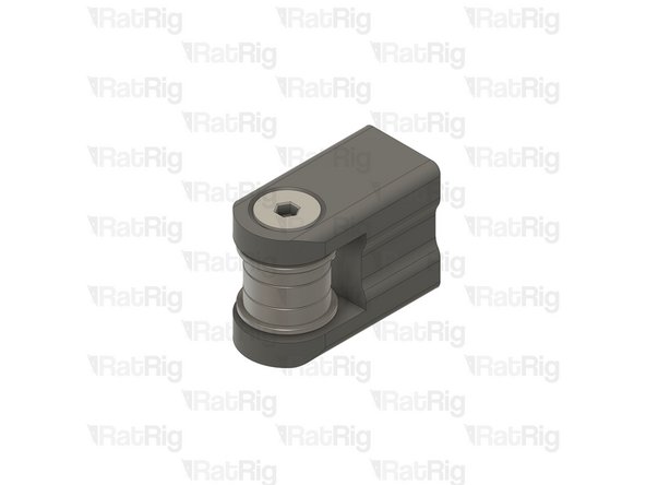
Insert the M5x22 Countersink Screw and tighten it to secure the assembly.
-
Repeat Steps 45 and 46 to assemble another three tensioner arms
-
-
-
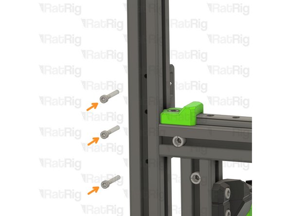
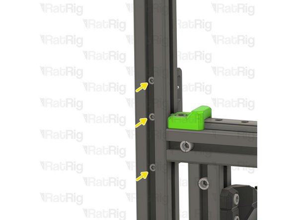
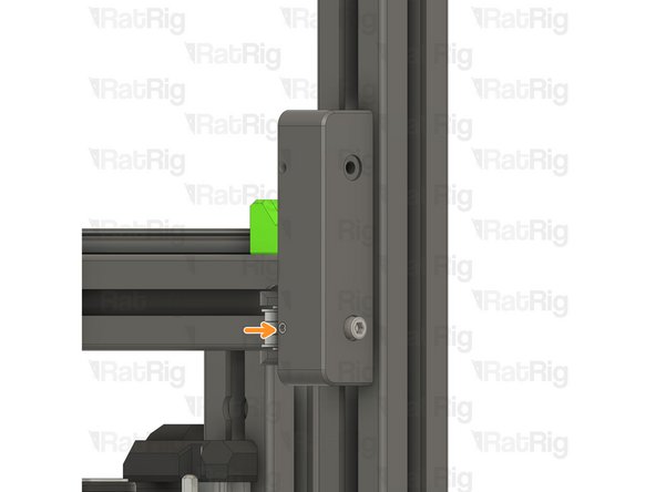
Rat Rig V-Core 4.0 - Tensioner Body - Right v1.0
-
3x M4x30 Cap Head Screws
-
Insert the screws through the holes on the V-Core 4 frame extrusion and thread them in the Tensioner Body - Right v1.0.
-
Tighten the M4x30 cap head screws.
-
-
-
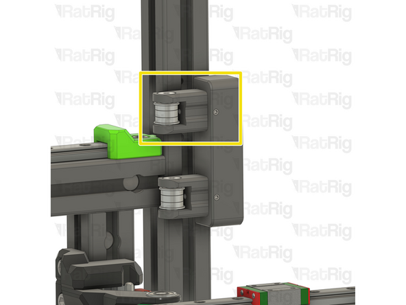
Front tensioner arm assembly from Step 46
-
Insert the tensioner arm in the lower slot of the tensioner body.
-
Make sure the tensioner arm has cleared the hole on the tensioner body.
-
M4x20 Cap Head Screw
-
Insert the screw through the tensioner body and lightly thread it to the tensioner arm.
-
The M4x20 screw must be partially, but not fully, threaded into the tensioner arm. This allows the largest possible range for tensioning the belts further in the guide.
-
-
-
M4x6 Set Screw
-
Tighten the Screw to secure the tensioner arm in place
-
Repeat Step 48 and install the top tensioner arm.
-
-
-
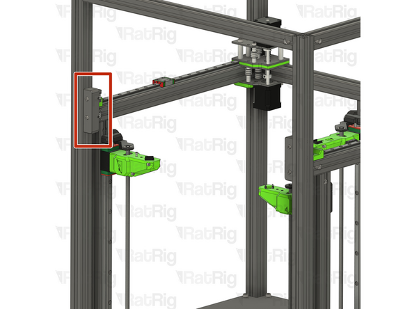
Repeat Steps 47, 48 and 49 and install the left front tensioner assembly.
-
-
-
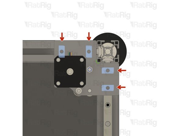
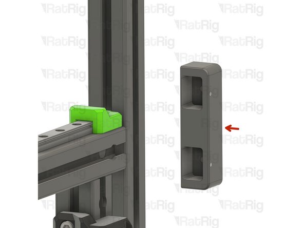
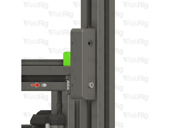
If you installed the Y-axis linear rail plastic stops in step 12 and step 14 of the Y-Axis Assembly guide, remove them now
-
Left-hand Y-axis linear rail plastic stop
-
Right-hand Y-axis linear rail plastic stop
-
The plastic stops are no longer required and can be discarded
-


Cancel: I did not complete this guide.
38 other people completed this guide.
