
-
-
25x Heat Insert M3
-
2x Heat Insert M4
-
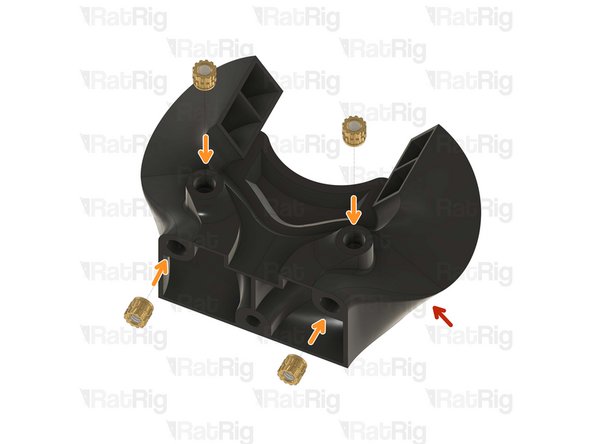
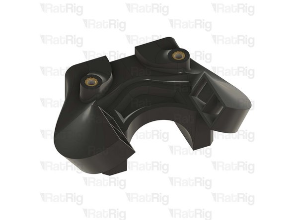
1x rr_vc4_toolhead_duct
-
2x rr_vc4_toolhead_back_clamp
-
1x rr_vc4_toolhead_front
-
1x rr_vc4_toolhead_toolboard_vertical
-
1x rr_vc4_toolhead_back
-
Clean the sacrificial layers on the rr_vc4_toolhead_back_clamp parts, obtaining a clean passthrough hole.
-
-
-
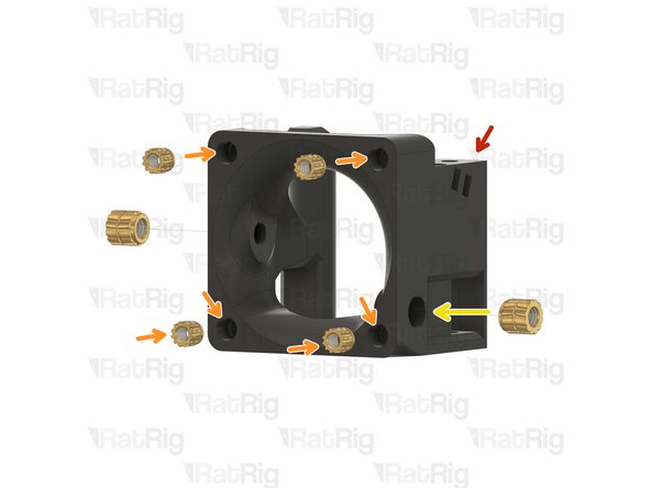
1x rr_vc4_toolhead_front
-
5x Heat Insert M3
-
2x Heat Insert M4
-
-
-
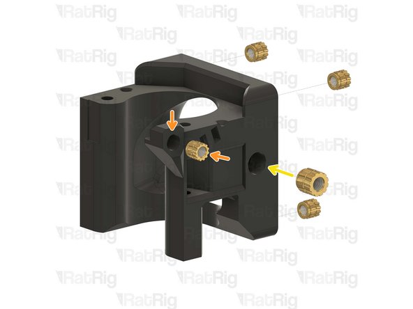
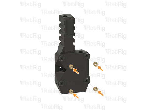
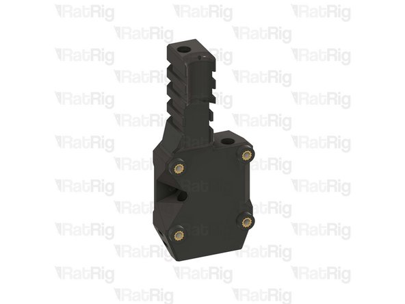
1x rr_vc4_toolhead_toolboard_vertical
-
4x Heat Insert M3
-
-
-
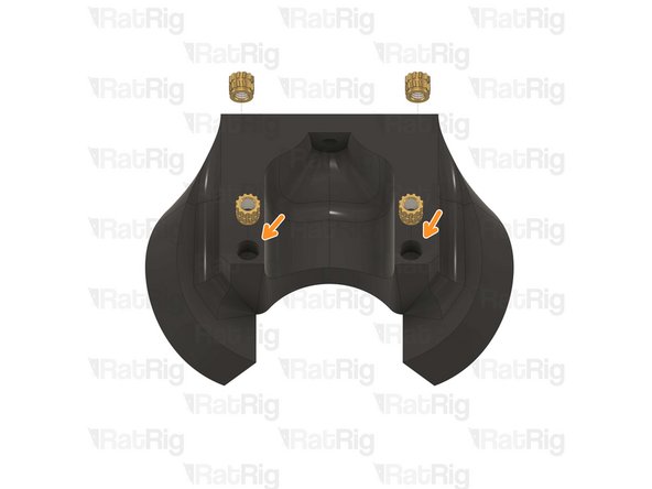
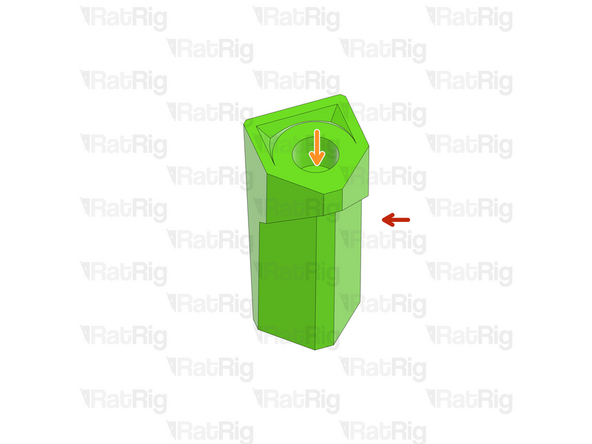
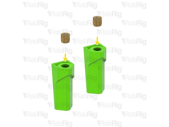
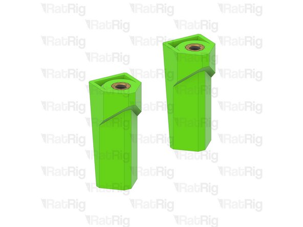
2x rr_vc4_toolhead_back_clamp
-
Remove the sacrificial layer
-
2x Heat Insert M3
-
-
-
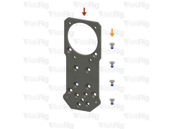
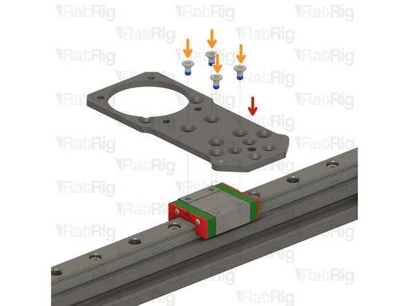
1x Rat Rig toolhead plate
-
4x M3x6 Countersink Screw with applied thread locker
-
-
-
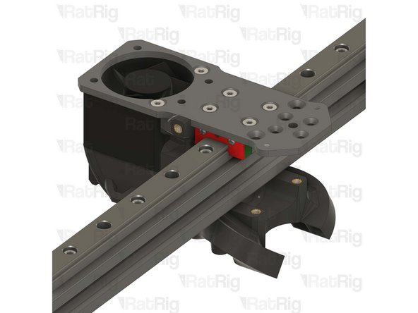
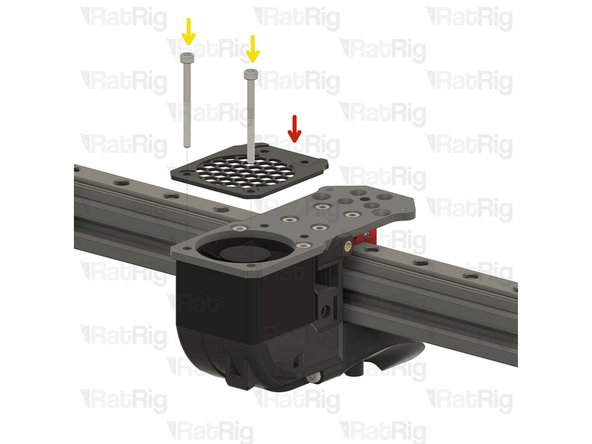
Rat Rig toolhead plate
-
4x M3x6 Countersink Screw
-
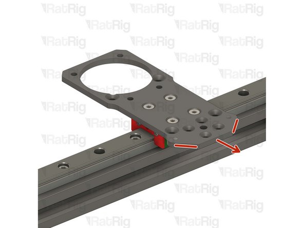
Tighten the M3x6 Countersink Screws to secure the plate to the carriage.
-
Pay attention to the orientation of the metal plate, having the pointy side towards the front of the printer, chamfered holes up.
-
Avoid using a ball end hex key, as they are more prone to damaging the sensitive M3 countersink screw head.
-
After tightening the screws, it is essential to verify that the X carriage retains its free movement. Excessive tightening of the screws may lead to the binding of the carriage.
-
-
-
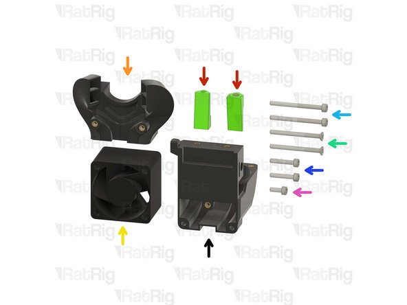
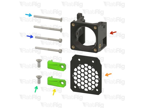
1x rr_vc4_toolhead_back
-
2x rr_vc4_toolhead_back_clamp
-
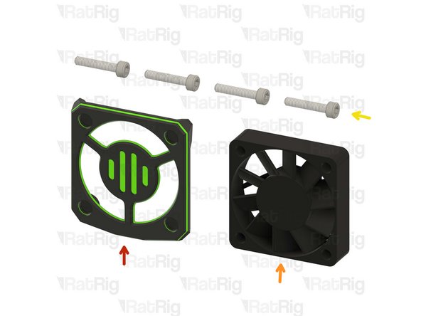
1x rr_vc4_toolhead_duct
-
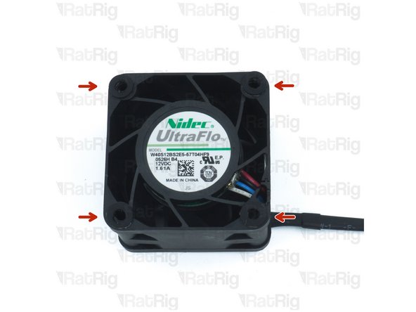
1x 4028 Part Cooling Fan
-
2x M3x35 Countersink Screw
-
2x M3x35 Cap Head Screw
-
2x M3x16 Cap Head Screw
-
1x M3x8 Cap Head Screw
-
-
-
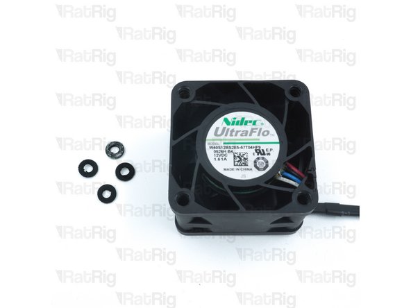
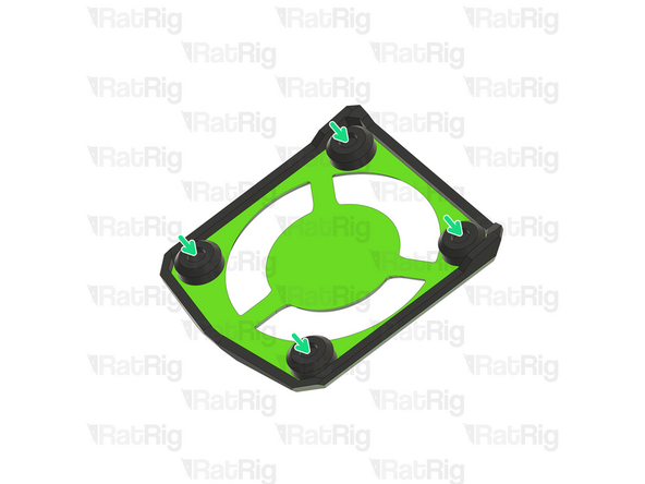
Remove the four rubber spacers on the 4028 Part Cooling Fan
-
-
-
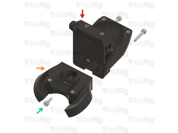
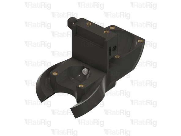
Rat Rig toolhead back printed part
-
Rat Rig toolhead duct printed part
-
2x M3x16 Cap Head Screw
-
1x M3x8 Cap Head Screw
-
Insert the M3x16 screws through the back part and tighten them into the duct.
-
Feed the M3x8 screw from the opposite side and secure the parts together.
-
Take care not to over tighten the screws as you can damage the printed parts.
-
-
-
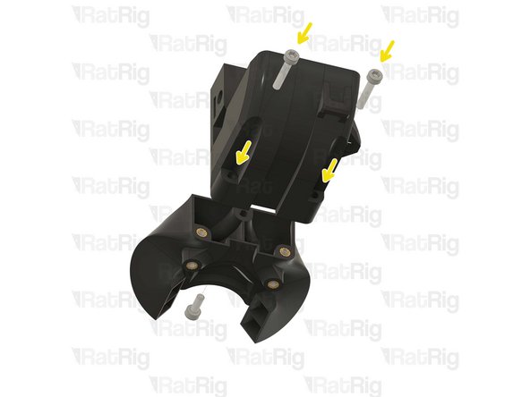
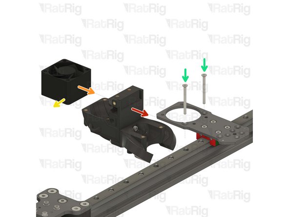
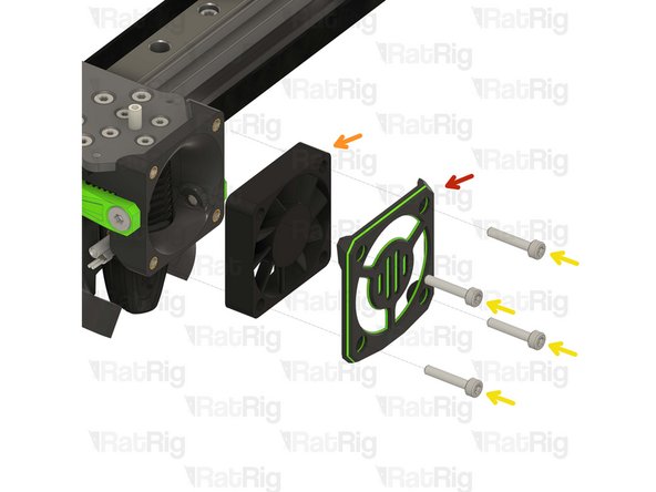
Back part & duct sub-assembly
-
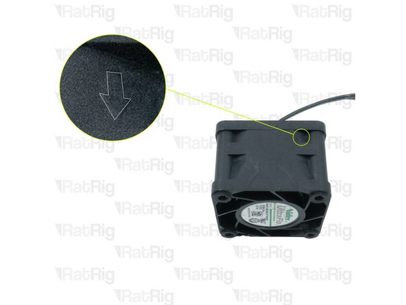
4028 Part Cooling Fan
-
Pay special attention to the fan airflow, it should blow the air towards the cooling duct. Most fans have a small arrow indicating the airflow.
-
Point the fan wires to this side.
-
2x M3x35 Countersink Screw
-
Feed the M3x35 screws into the toolhead plate, through the 4028 part cooling fan and tighten them into the printed sub-assembly.
-
Take care not to over tighten the M3x35 screws as you can damage the printed parts
-
Avoid using a ball end hex key, as they are more prone to damaging the sensitive M3 countersink screw head.
-
-
-
1x rr_vc4_toolhead_front
-
1x rr_vc4_toolhead_fan_grille
-
2x rr_vc4_toolhead_front_clamp
-
2x M4x10 Countersink Screw
-
2x M3x40 Countersink Screw
-
2x M3x35 Cap Head Screw
-
-
-
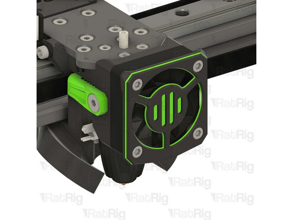
Rat Rig toolhead fan grille printed part
-
Rat Rig toolhead front printed part
-
2x M3x35 Cap Head Screw
-
Feed the M3x35 cap head screws through the grille (pay close attention to its orientation), the aluminium plate and the 4028 fan, tightening them into the back printed part.
-
2x M3x40 Countersink Screw
-
The M3x40 countersink screws must go through the holes on the front assembly and thread into the duct assembly.
-
Take care not to over tighten the screws as you can damage the printed parts
-
Avoid using a ball end hex key, as they are more prone to damaging the sensitive M3 countersink screw head.
-
-
-
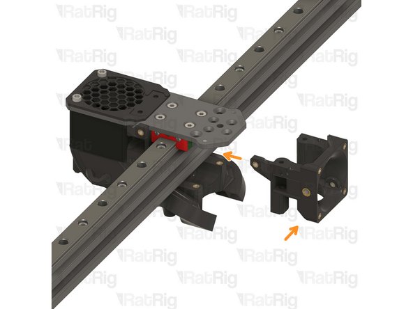
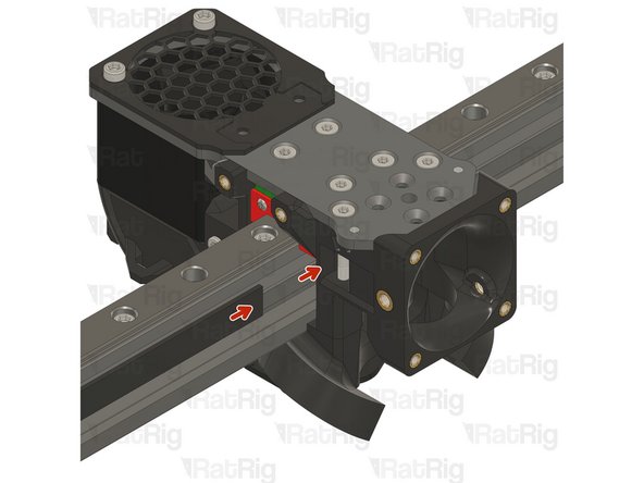
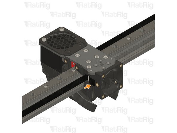
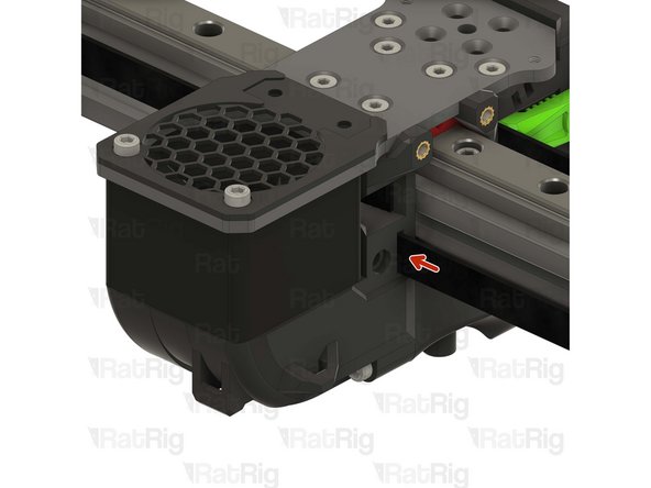
Insert the belt in the designated slot, and ensure the belt end is fed from behind the screw.
-
Pull the belt end and gently place it inside the groove.
-
The belt teeth must be facing the front of the machine.
-
-
-
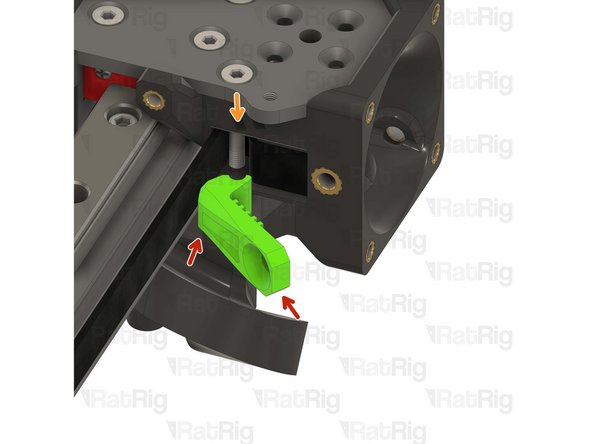
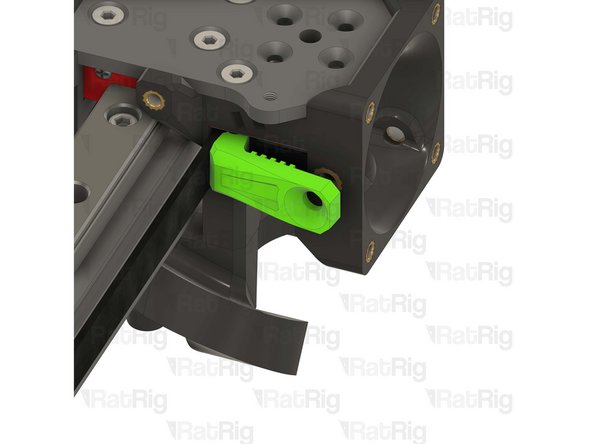
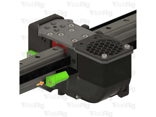
Rat Rig toolhead front belt clamp
-
Lever the belt clamp against the exposed screw section and place it inside the belt slot.
-
-
-
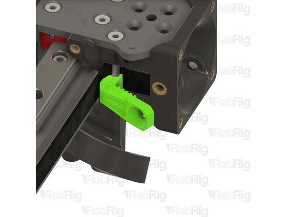
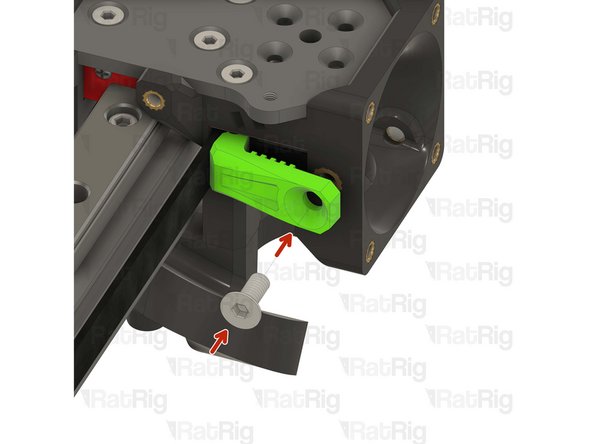
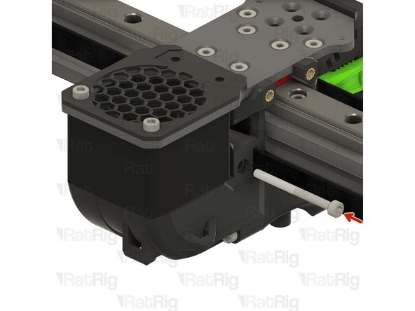
1x M4x10 Countersink Screw
-
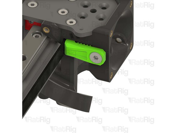
Tighten the M4x10 screw making sure the teeth of the belt clamp mesh with the belt
-
Pay attention to seating the notch on the belt clamp on the exposed screw section. Pull on the belt to make sure it's secured properly.
-
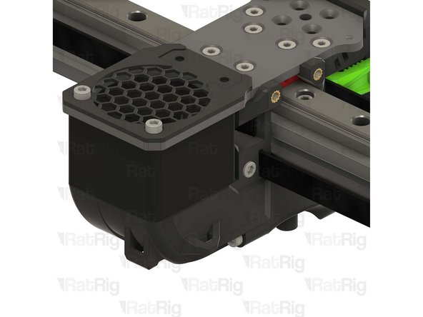
Repeat Steps 15, 16 and 17 to attach the other belt
-
-
-
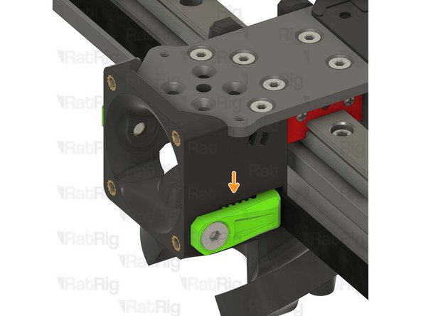
Feed the belt inside the slot on the back part of the toolhead.
-
Rat Rig toolhead back belt clamp
-
Insert the back belt clamp from the other side of the toolhead, while keeping some excess belt.
-
-
-
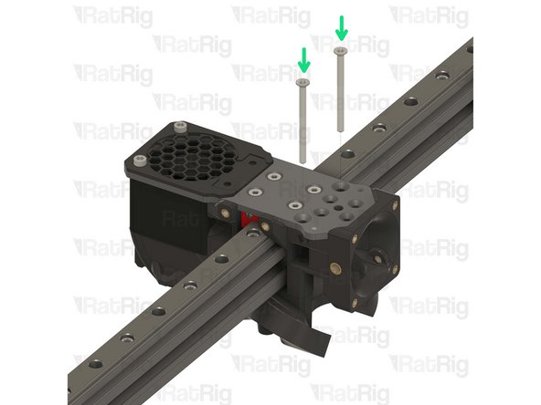
M3x35 Cap Head Screw
-
Tighten the M3x35 Cap Head screw while pulling on the belt from the other side.
-
-
-
Cut the excess belt.
-
Repeat Steps 18, 19 and 20 to attach the other belt.
-
The Hybrid belts will be installed later.
-
-
-
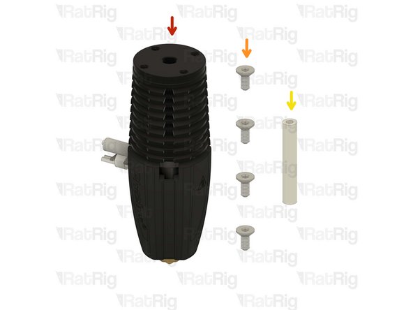
Phaetus Rapido V2 UHF Hotend
-
4x M2.5x6 Countersink Screw
-
PTFE tube - 24.5mm
-
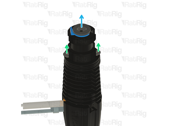
Remove the two countersink screws on top of the rapido
-
Remove the V6-style adapter, it is not required for the RatRig toolhead
-
-
-
Phaetus Rapido V2 UHF
-
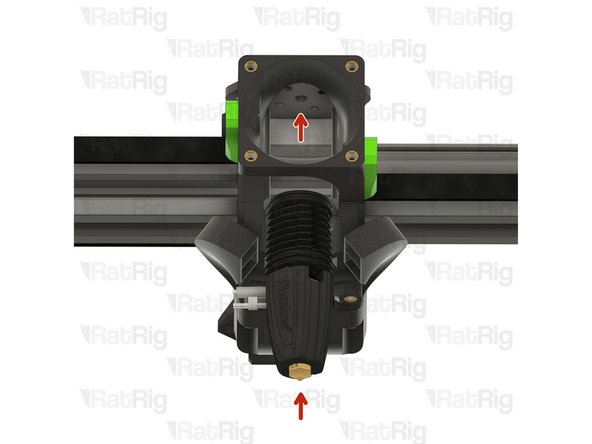
Place the Phaetus Rapido V2 UHF Hotend on the plate, making sure to route the cables through the designated slot
-
Look from above and see if all four holes line up correctly.
-
All the holes on the plate, hotend and printed part should line up:
-
If they align skip to Step 26
-
If they don't align follow the next steps
-
-
-
If the cables of your Rapido 2 hotend don't align perfectly with the toolhead slot, please follow the next steps:
-
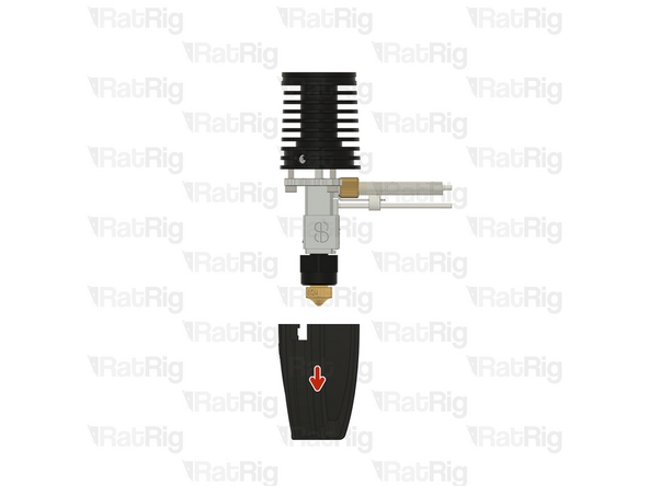
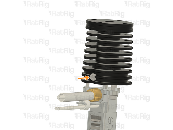
Push down on the silicone sock to remove it
-
Loosen the set screw on the heatsink
-
Do not remove it completely to avoid losing it
-
-
-
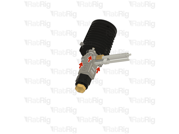
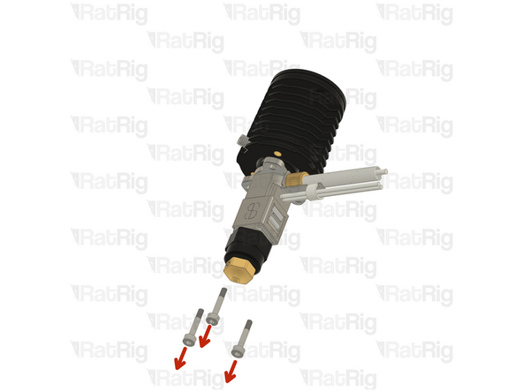
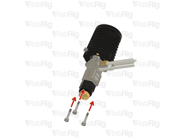
Remove the 2.5mm Cap Head Screws from the hotend
-
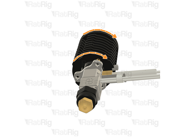
Carefully rotate the heatsink until the three screw holes align again.
-
There isn't a way to tell how much you need to rotate you hotend, it might be just 120º or it might be 240º. It's a matter of trial and error.
-
-
-
Insert the 2.5mm Cap Head Screws back in and tighten them.
-
DO NOT overtighten the screws, they are only 2.5mm and will break if excessive force is applied.
-
Tighten the set screw back in
-
DO NOT overtighten the screw, if excessive force is applied the heatbreak will be permanently damaged.
-
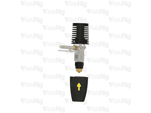
Put the socket back on
-
Try to insert the hotend on the toolhead and see if the cables align with the designated slot, if not, repeat Steps 23, 24 and 25 and try a different angle in Step 22
-
-
-
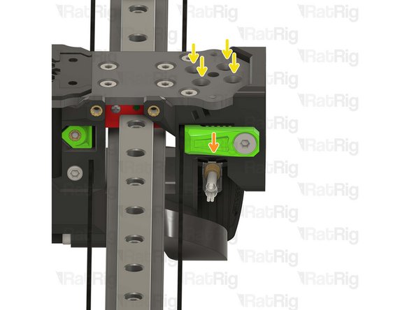
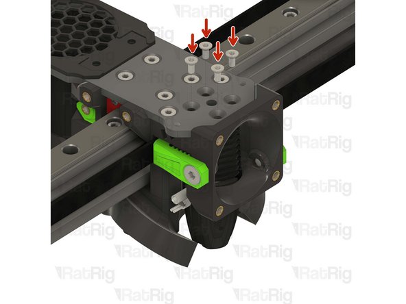
4x M2.5x6 Countersink Screw
-
Tighten the M2.5x6 Countersink Screws to secure the hotend to the plate.
-
Avoid using a ball end hex key, as they are more prone to damaging the sensitive M2.5 countersink screw head.
-
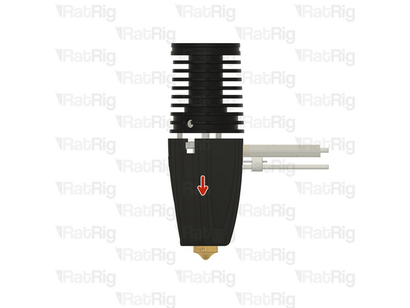
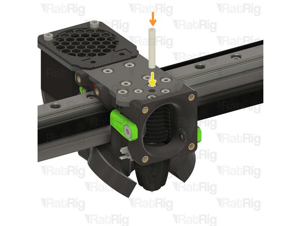
PTFE tube - 24.5mm
-
Insert the PTFE tube in to the marked hole and push it until it stops.
-
-
-
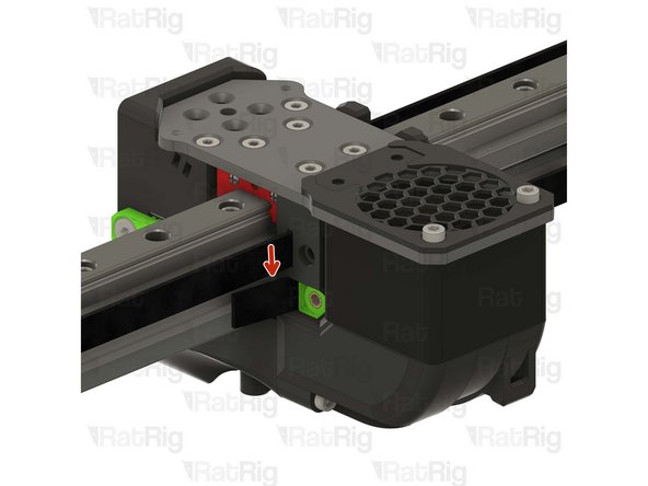
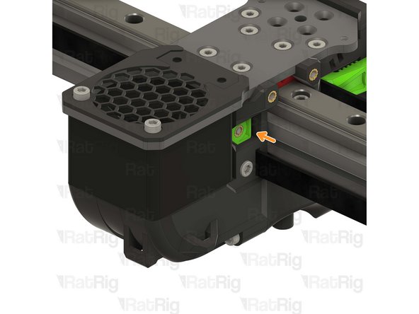
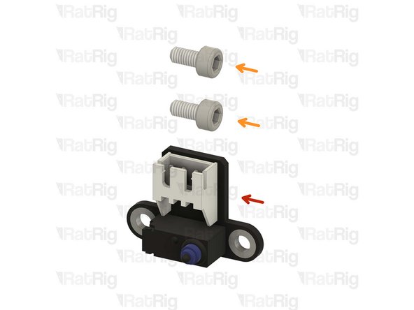
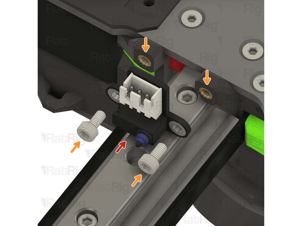
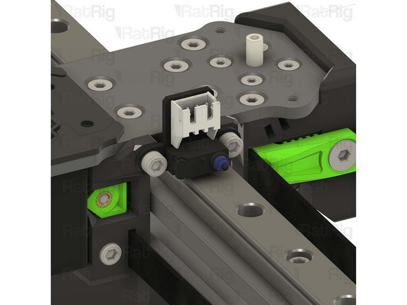
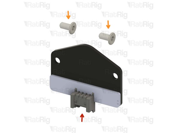
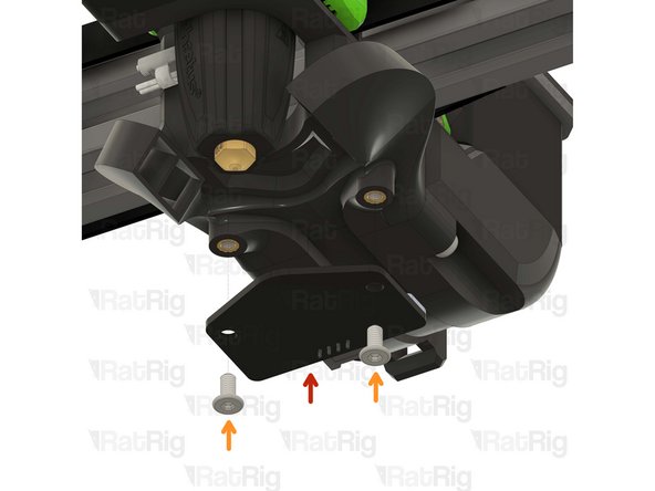
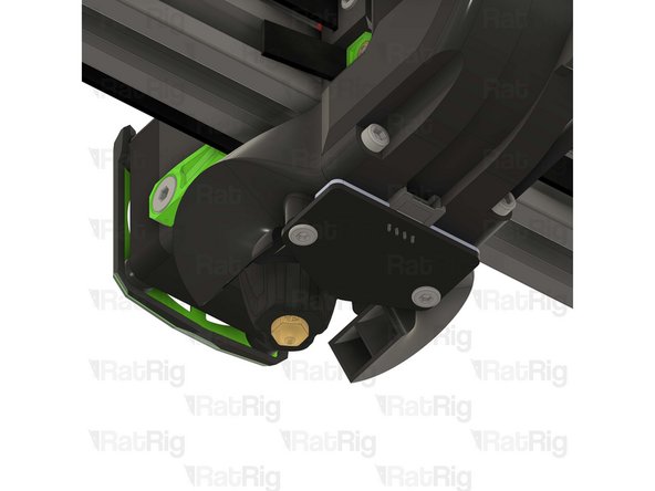
Rat Rig X Endstop
-
2x M3x6 Cap Head Screw
-
Tighten the M3x6 screws to secure the X endstop to the toolhead.
-
Take care not to over tighten the M3x6 screws as you can damage the printed parts.
-
-
-
1x rr_vc4_toolhead_shroud
-
40x10mm 24V Axial Fan
-
4x M3x16 Cap Head Screw
-
Remove the sacrificial layers from the back of the rr_vc4_toolhead_shroud
-
-
-
Rat Rig toolhead fan shroud printed part
-
40x10mm 24V Axial Fan
-
The wires should be positioned where the arrow points.
-
4x M3x16 Cap Head Screw
-
Insert the M3x16 screws into the Rat Rig toolhead shroud printed part, through the 40mm fan, and fasten them into the Rat Rig toolhead front.
-
Take care not to over tighten the M3x16 screws as you can damage the printed parts.
-
Pay special attention to the fan airflow, it should blow the air towards the hot end heat sink. Most fans have a small arrow indicating the airflow. If not, the the fan label should be facing the hotend.
-
-
-
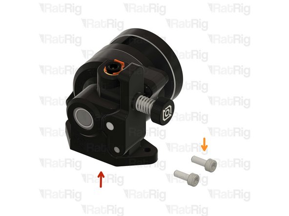
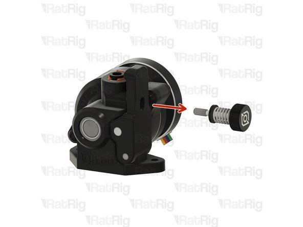
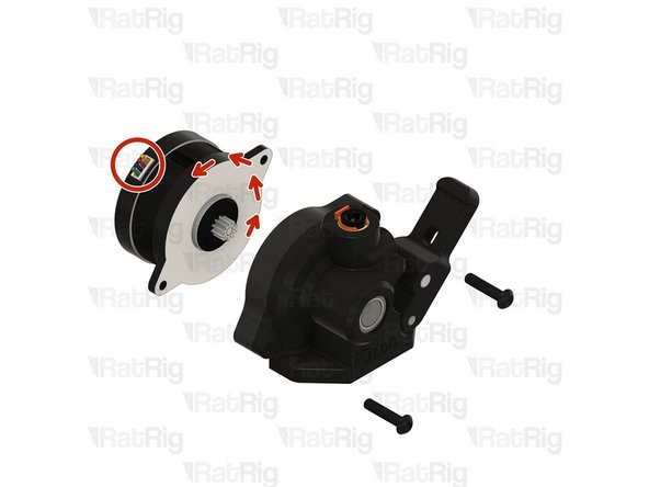
Remove the tensioning screw
-
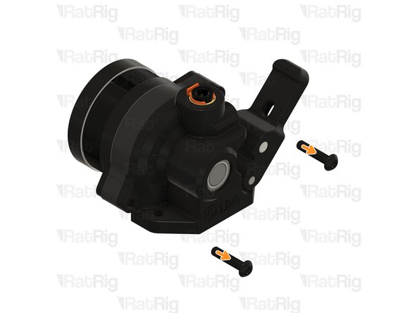
Remove the two front screws
-
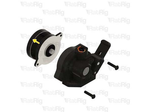
Carefully detach (or rotate) the stepper motor from the housing
-
-
-
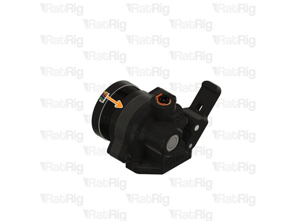
Rotate the stepper motor 180º until the wires come out from the top.
-
Carefully reinstall the stepper on the housing.
-
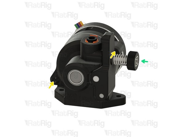
Install the front screws
-
Install the tensioning screw
-
-
-
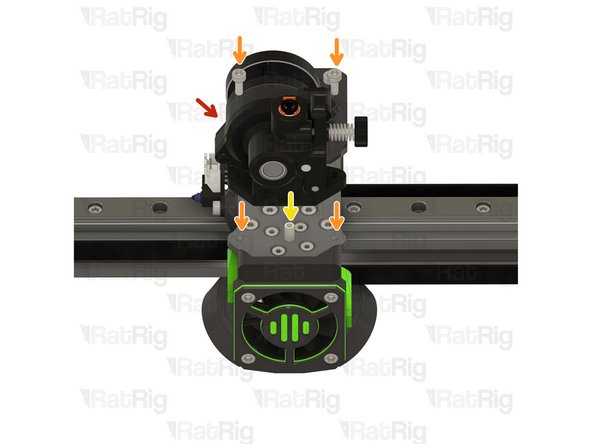
LDO Orbiter V2
-
2x M3x8 Cap Head Screw
-
Carefully align the extruder with the PTFE tube.
-
Insert the M3x8 screws into the LDO Orbiter V2 and fasten them to the Rat Rig toolhead plate.
-
Take care not to over tighten the M3x8 screws as you can strip the toolhead plate threads
-
-
-
Beacon Rev H Low Profile
-
Rat Rig recommends connecting the beacon's cable before mounting it to ensure the connector is fully and securely inserted.
-
2x M3x6 Wafer Head Screw
-
Tighten the M3x6 screws to secure the Beacon to the toolhead.
-
Take care not to over tighten the M3x6 screws as you can damage the PCB and the printed parts.
-
-
-
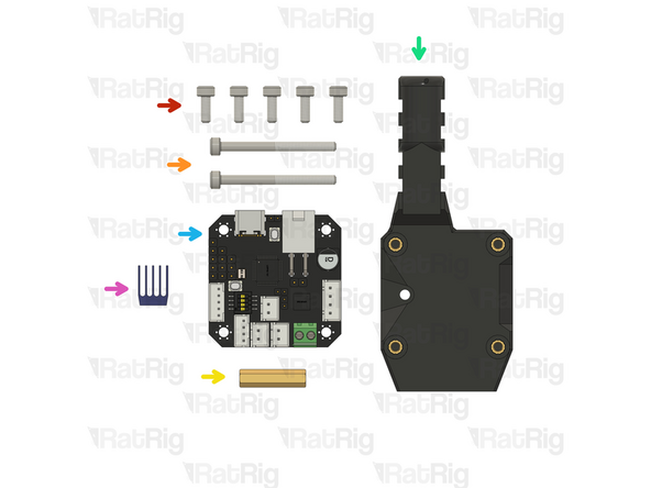
5x M3x8 Cap Head Screw
-
2x M3x35 Cap Head Screw
-
1x Hex standoff M3x20x4.5
-
rr_vc4_toolhead_toolboard_vertical
-
BIGTREETECH EBB42 USB/CAN TOOLBOARD V1.2
-
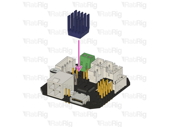
TMC2209 driver heatsink (included in the EBB42 box)
-
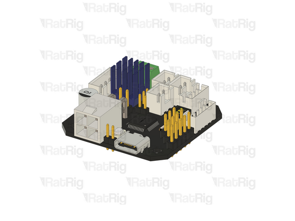
Remove the adhesive backing from the heatsink and gently press it onto the TMC2209 driver.
-
-
-
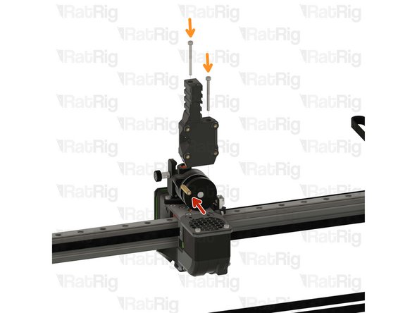
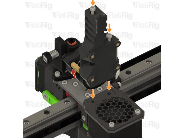
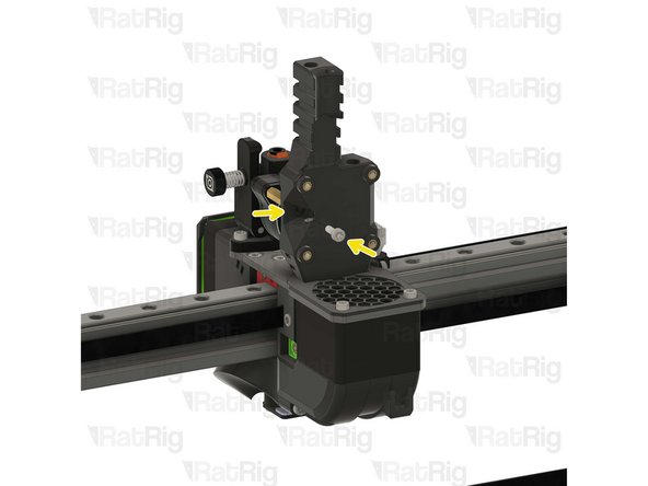
Thread the hex standoff on to the LDO Orbiter V2 screw.
-
Do not overtighten the hex standoffs. They are brass and it is possible to strip the threads.
-
Insert the M3x35 screws into the Rat Rig toolhead vertical toolboard mount printed part and secure it onto the toolhead.
-
Take care not to over tighten the M3x35 screws as you can damage the printed parts.
-
1x M3x8 Cap Head Screw
-
Insert the M3x8 screw through the printed part and into the thread to attach it to hex standoff.
-
-
-
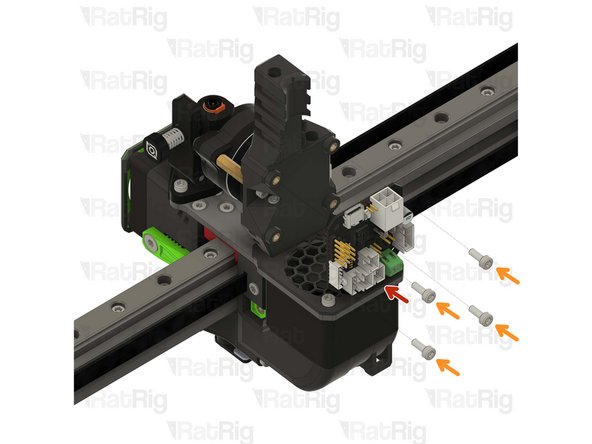
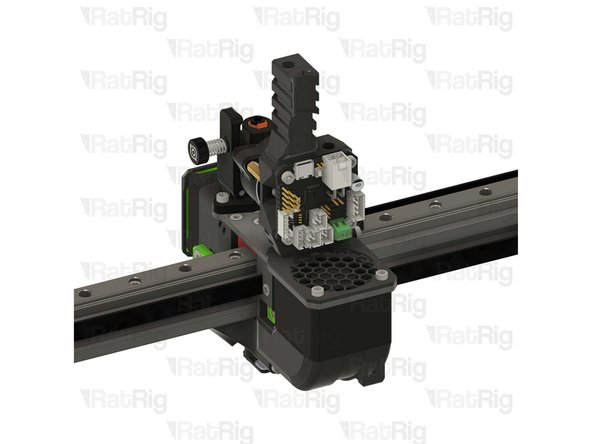
BIGTREETECH EBB42 USB/CAN TOOLBOARD V1.2
-
4x M3x8 Cap Head Screw
-
Insert the M3x8 screws into the toolboard and thread them into the Rat Rig toolhead vertical toolboard mount printed part
-
-
-
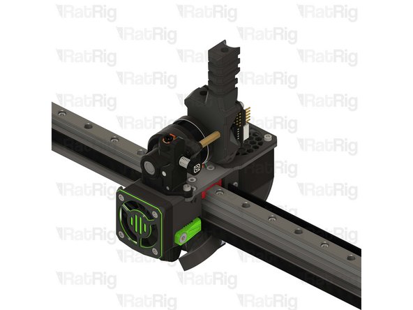
Your V-Core 4 now has the Rat Rig Toolhead installed and it's ready to melt some filament!
-


Cancel: I did not complete this guide.
21 other people completed this guide.

2 Comments
I would have prefered the change of connector being described here and not in chapter 12
JeanPhi 35 - Resolved on Release Reply