
Steps
28
- 12. Enclosure Panels 28 steps

User-Contributed Guide
This guide is not managed by the site's staff.
Quiz
0
Introduction
Rat Rig provides DXF and STEP files for you to have your own panels produced locally. These are available for download on the Rat Rig V-Core 3 GitHub repository
-
-
2x panel_enc2_side_size
-
1x panel_enc2_door_size
-
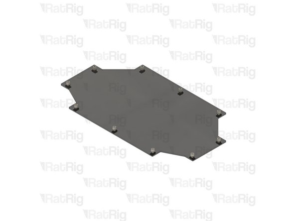
1x panel_enc2_top_size
-
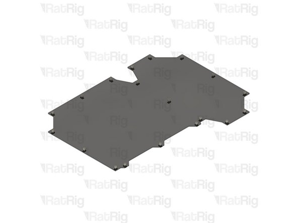
1x panel_enc2_back_size
-
Use the file with the correct size for your printer (200, 300, 400 or 500)
-
-
-
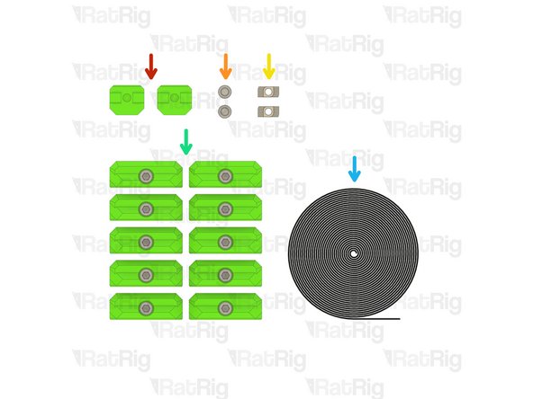
4x Rat Rig nylon door handle
-
10x Panel magnet mount assemblies
-
8x M6x16 Cap Head Screw
-
8x M6 Nylon Locking Hex Nut
-
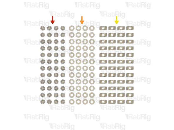
24x M6x12 Cap Head Screw
-
24x M6 Washer
This is also a good time to print the optional panel trim pieces if they will be used to cover the small gaps between the panels and the frame. The trim pieces need to be installed with the side and back panels as they mount using the same M6 screws.
Mark Ewert - Resolved on Release Reply
-
-
-
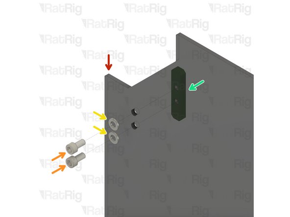
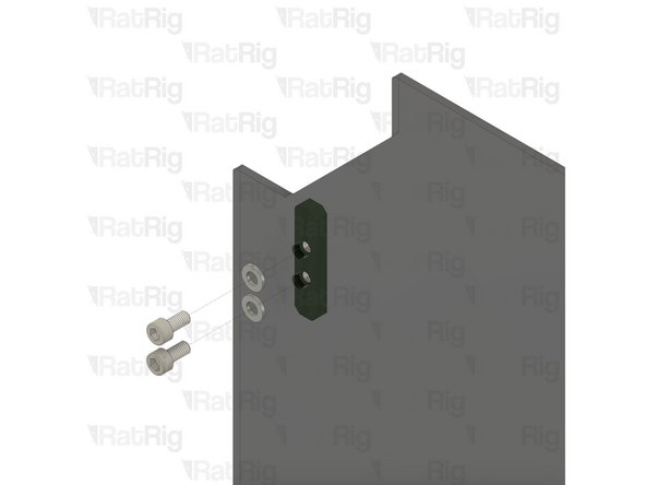
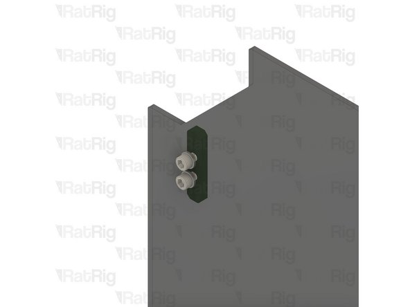
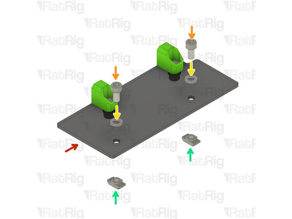
There are 6 magnet mount positions on the door (or 4 on the 200). Repeat the following for each of them
-
panel_enc2_door_size
-
M6x12 Cap Head Screw
-
M6 Washer
-
Panel magnet mount assembly
-
Take care not to over tighten the M6x12 screw as you can damage the printed parts
-
-
-
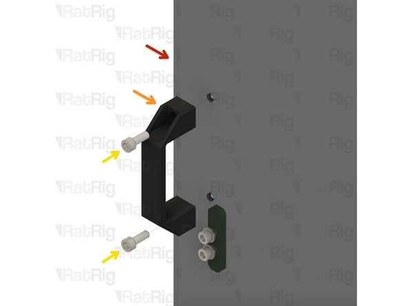
There are 2 handle positions on the door. Repeat the following for each of them
-
panel_enc2_door_size
-
Rat Rig nylon door handle
-
M6x16 Cap Head Screw
-
M6 Nylon Locking Hex Nut
-
Do not overly tighten the M6 nylon locking hex nuts when securing the handles, as this can cause the panel to warp which will prevent a good seal to the printer
-
-
-
Completed door panel assembly
-
Set the completed door assembly aside until Step 18
-
-
-
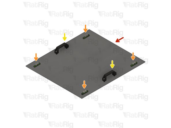
panel_enc2_top_size
-
Install four of the panel magnet mount assemblies to the top panel
-
Take care not to over tighten the M6x12 screw as you can damage the printed parts
-
Install two of the Rat Rig nylon handles to the top panel
-
Do not overly tighten the M6 nylon locking hex nuts when securing the handles, as this can cause the panel to warp which will prevent a good seal to the printer
-
Set the completed top assembly aside until Step 16
-
-
-
48x M6x12 Cap Head Screw
-
48x M6 Washer
-
48x 3030 Drop-in T-Nut - M6
-
-
-
panel_enc2_side_size
-
M6 Washer
-
M6x12 Cap Head Screw
-
3030 Drop-in T-Nut - M6
-
Loosely thread the 3030 T-Nuts onto the M6x12 screws. Do not tighten them at this point.
If you plan to use the optional panel trim pieces to cover the small gaps between the panels and frame, be sure to install them when you install each panel. They mount with the panel using the M6 screws without the washers. The washers should still be used wherever the panel mounts without a trim piece.
Mark Ewert - Resolved on Release Reply
-
-
-
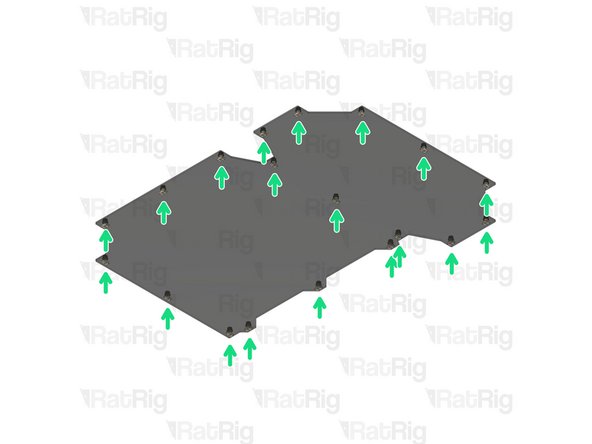
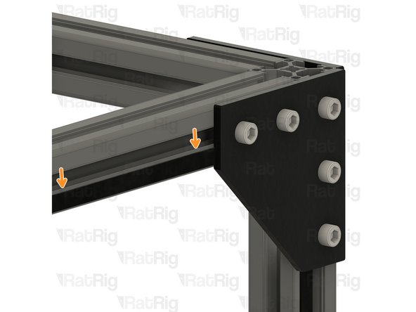
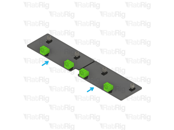
Repeat the previous steps to install an M6x12 cap head screw, M6 washer and 3030 drop-in t-nut to each hole on the remaining panels as shown
-
Set all panels aside until Steps 19, 20 & 21
-
-
-
2x 3030_panel_mount_horizontal printed part
-
2x M6x12 Cap Head Screw
-
2x 3030 Drop-in T-Nut - M6
-
10x Frame magnet mount assembly
-
1x Adhesive backed foam sealing tape
-
-
-
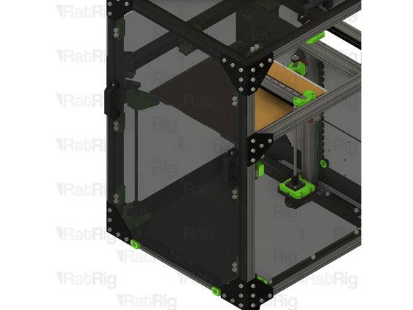
Adhesive foam tape
-
Cut sections of foam tape to fit in the sections shown
-
The foam seal tape is provided with an adhesive backing, peel the backing off and apply it to the frame as shown
The base panel can be installed at any point, as you can still get it through the door once everything is assembled
-
-
-
Following the instructions in the previous step, apply the foam tape around the top extrusions as well
-
-
-
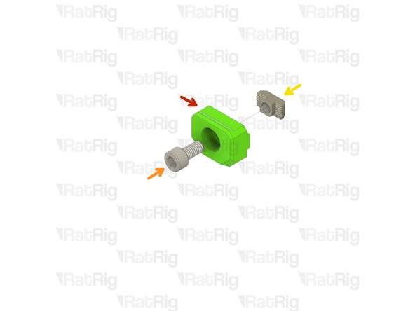
3030_panel_mount_horizontal printed part
-
M6x12 Cap Head Screw
-
3030 Drop-in T-Nut - M6
-
Loosely thread the 3030 T-Nuts onto the M6x12 screws. Do not tighten them at this point.
-
-
-
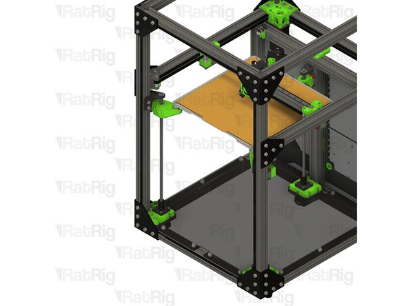
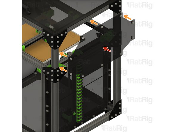
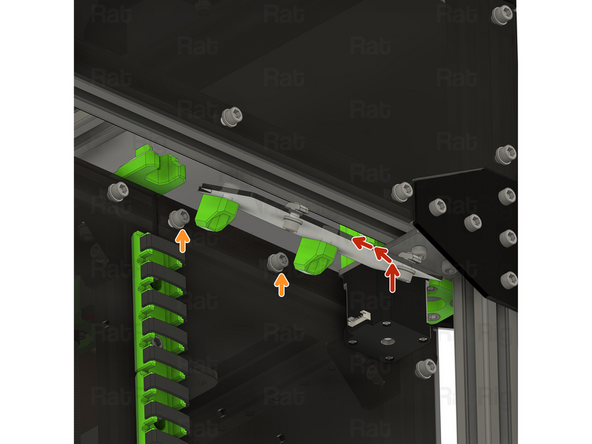
Horizontal 3030 panel holder assembly from Step 13
-
Align the 3030 panel holder assemblies as shown
-
Tighten the M6x12 screws to secure the assemblies to the frame
-
Take care not to over tighten the M6x12 screws as you can damage the printed parts
-
-
-
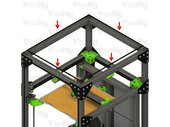
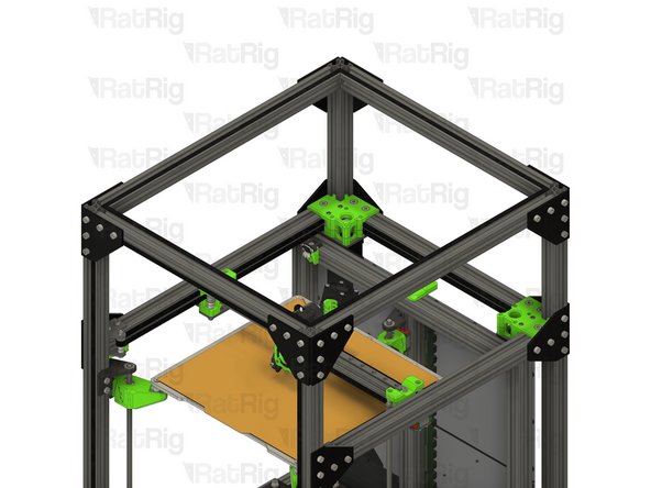
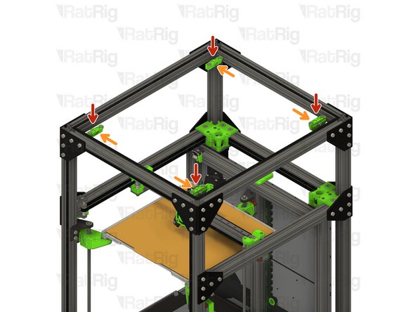
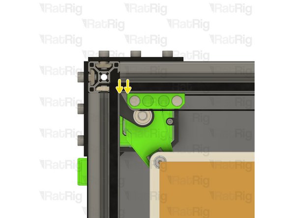
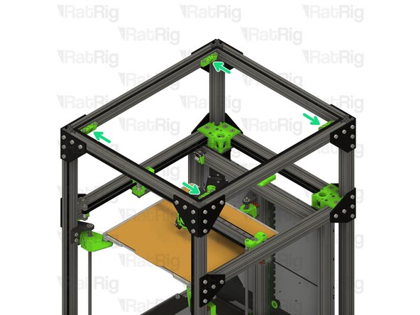
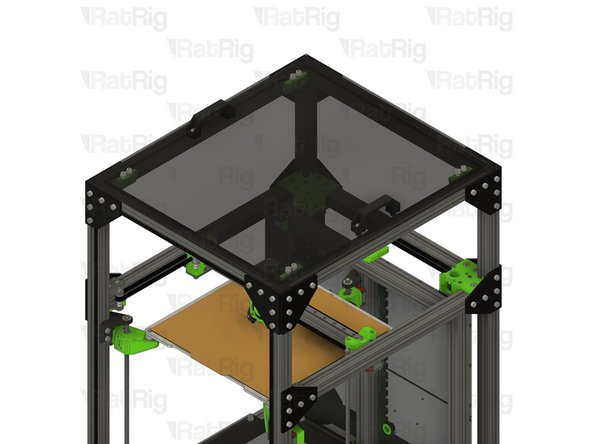
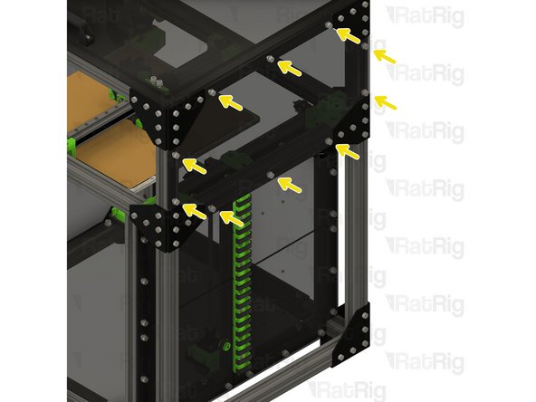
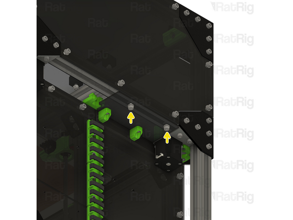
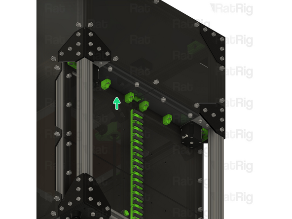
Frame magnet mount assembly
-
Position each magnet mount assembly as shown
-
The marked gap should measure 6.50mm
-
Tighten the M6x12 screw to secure each assembly to the frame
-
Take care not to over tighten the M6x12 screws as you can damage the printed parts
-
The exact position of the magnet mounts can be adjusted once the top panel in in place
-
-
-
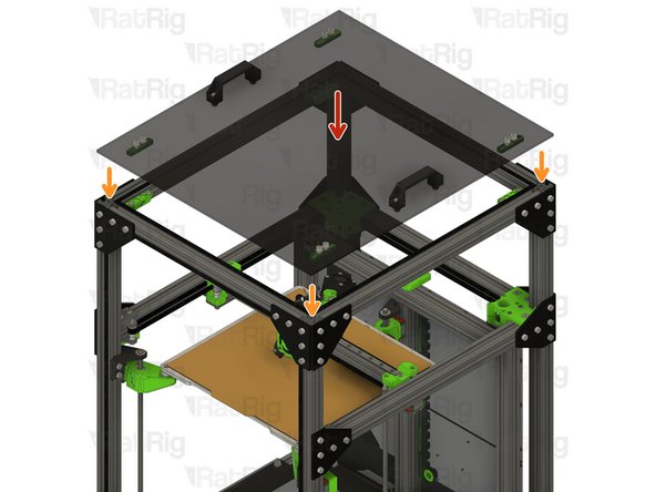
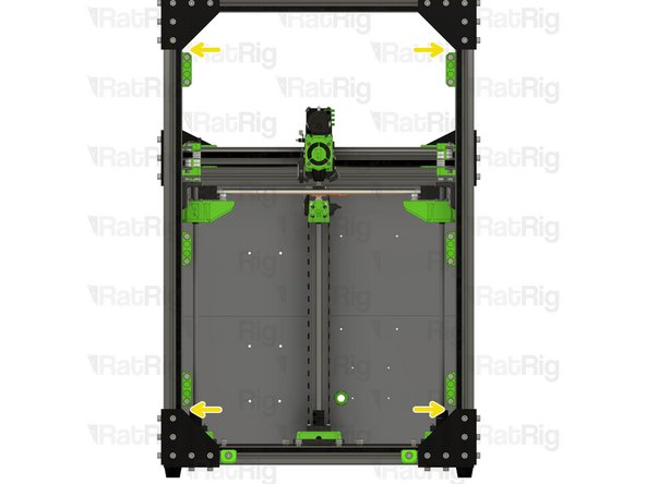
Top panel assembly from Step 6
-
Place the top panel onto the top of the printer
-
The magnets should align the panel automatically. If the alignment needs to be adjusted, alter the position of the magnet holders installed in Step 15
-
-
-
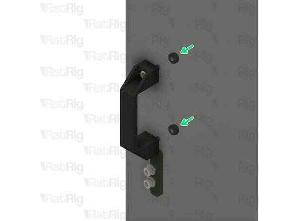
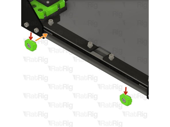
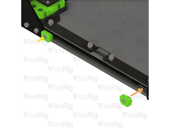
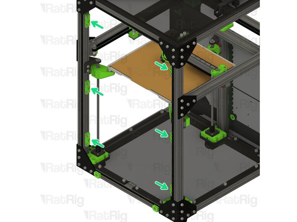
Frame magnet mount assembly
-
Position each magnet mount assembly as shown
-
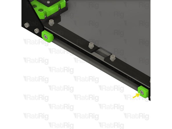
The marked gaps should measure 5mm
-
It is easiest to align the central magnet mounts once the door panel is in place, position them roughly in the middle for now
-
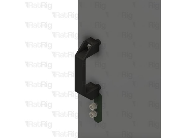
Tighten the M6x12 screw to secure each assembly to the frame
-
Take care not to over tighten the M6x12 screws as you can damage the printed parts
-
The exact position of the magnet mounts can be adjusted once the door is in place
-
-
-
Door panel assembly from Step 5
-
Rest the door panel on the horizontal 3030 panel mounts, then rotate towards the printer to secure it
-
The magnets should align the panel automatically. If the alignment needs to be adjusted, alter the position of the magnet holders installed in Step 17
-
-
-
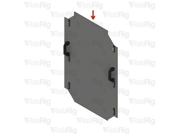
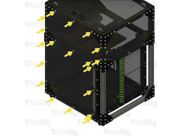
Rear enclosure panel from Step 9
-
Align the panel to the frame as shown
-
Secure the panel in place by fastening the ten M6x12 screws
-
-
-
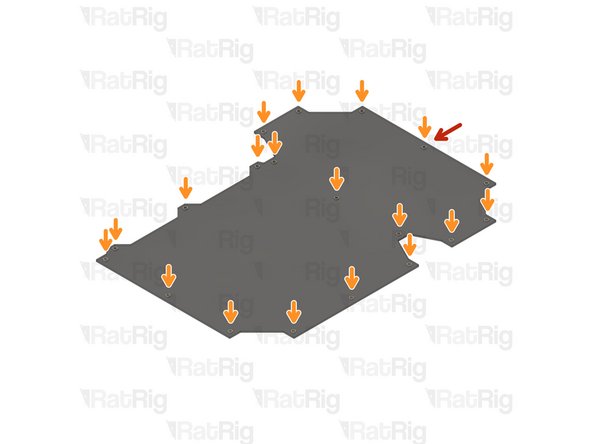
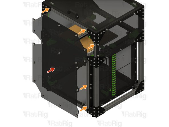
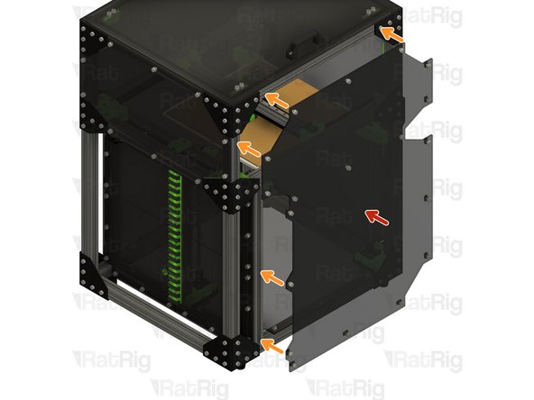
Right enclosure panel from Step 9
-
Align the panel to the frame as shown
-
Secure the panel in place by fastening the nineteen M6x12 screws
-
-
-
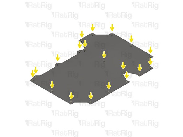
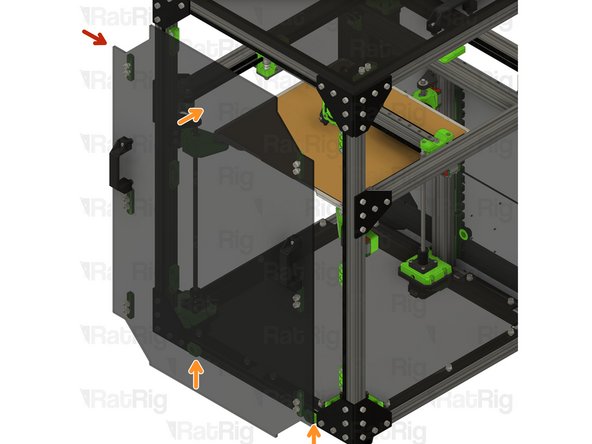
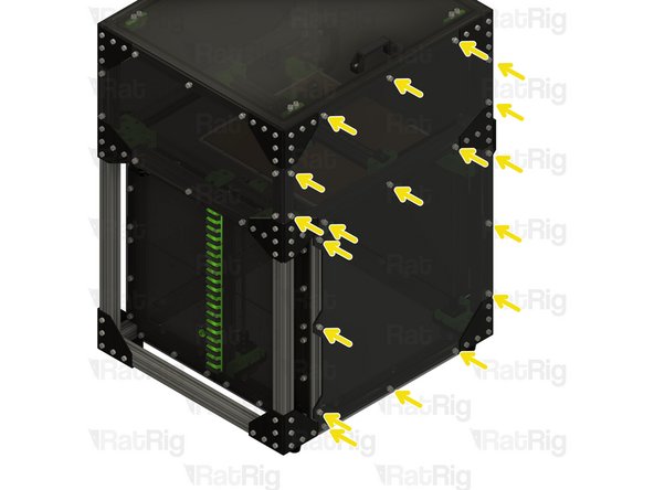
Left enclosure panel from Step 9
-
Align the panel to the frame as shown
-
Secure the panel in place by fastening the nineteen M6x12 screws
-
-
-
Rat Rig has developed, and provide, a set of optional extra printed parts for the V-Core 3 Enclosure 2.0
-
Parts available include:
-
Panel trims for the exterior of the enclosure
-
A brand-new, side-mounted, printable spool holder
-
A rear shelf, designed to sit above the electronics and help fully enclose the print volume
-
The rear shelf printed parts were replaced with CNC cut panels in the original kit, since February 2024. Note: The V-Core 3.1 200 still ships with a printed rear shelf.
-
Other miscellaneous parts
-
Parts can be found on the V-Core 3 project pages and the Rat Rig Lab site
-
-
-
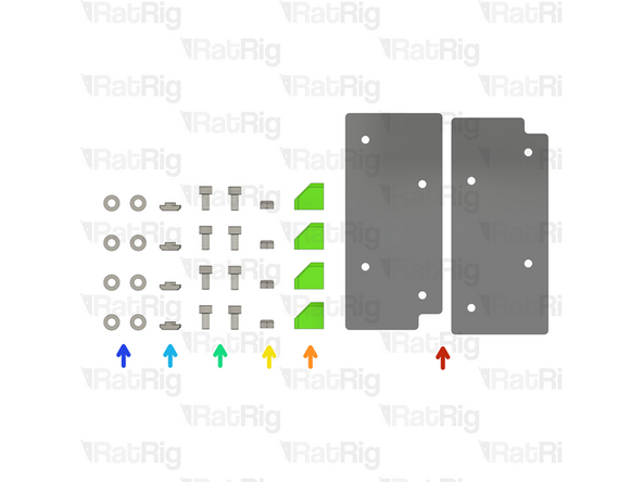
The rear shelf printed parts were replaced with CNC cut panels in the original kit, since February 2024. Except for the V-Core 3.1 200, as the panel is much smaller.
-
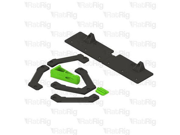
The V-Core 3.1 300 has a single panel instead of two split panels, the assembly steps are the same:
-
2x VC31_panel_shelf
-
4x shelf_support printed part
-
4x M6 Nylon Locking Hex Nut
-
8x M6x12 Cap Head Screw
-
4x 3030 Drop-in T-Nut - M6
-
M6 Washer
-
-
-
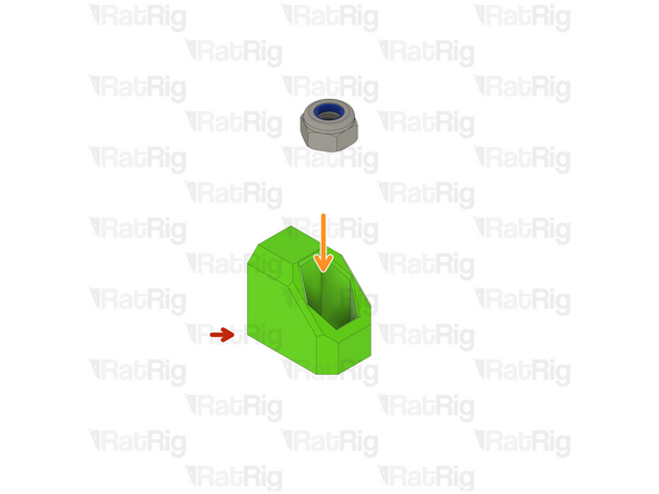
shelf_support printed part
-
M6 Nylon Locking Hex Nut
-
Assemble 4 shelf support printed parts.
-
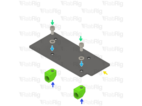
VC31_panel_shelf
-
M6x12 Cap Head Screw
-
M6 Washer
-
Shelf support assembly
-
-
-
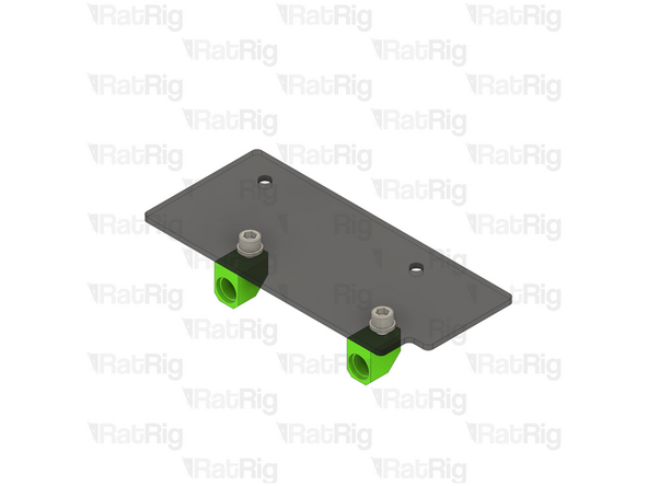
Rear shelf assembly from the previous step.
-
2x M6x12 Cap Head Screw
-
2x M6 Washer
-
2x 3030 Drop-in T-Nut - M6
-
Repeat Steps 24 and 25 and assemble another rear shelf (if applicable).
-
-
-
Insert the rear shelf assembly as shown
-
The M6 Cap Head Should be inserted inside the shelf_support printed part
-
Tighten the M6x12 cap head screws
-
Repeat and install the other rear shelf assembly
-
-
-
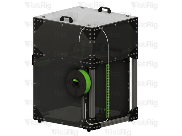
It is recommended to use a length of PTFE tube to route the filament into the enclosure as shown
-


Cancel: I did not complete this guide.
5 other people completed this guide.
3 Comments
1. what kind of magnets are needed?
2. what sizes and how much foam tape should there be?
3. what exactly are the models of the additional parts from the 22 points called?
1. Magnets (D10mmx4mm) are listed in the BOM here: https://v-core.ratrig.com/bom/#rat-rig-v...
2. foam tape is 5mm wide, 1mm thick. Included in the kit is enough for the top and front panels (length depends on printer size).
3. Models are listed here: https://v-core.ratrig.com/printed_parts/...
Nowhere can I find when is the best time to install the bottom acrylic sheet. Can it be done at this stage or is it too late and must be installed when assembling the frame like the Electronic panel?
S. Clement - Resolved on Release Reply
The bottom panel can be installed at any point, you can still get it through the door once everything is assembled.
Jérôme Pirotte -