
-
-
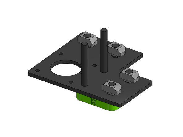
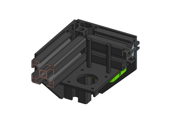
Fetch these six parts and look for letters indicating which parts belong to which side:
-
The letter L for left
-
The letter R for right
-
The sides do not differ much, but the parts are NOT mirrored
-
-
-
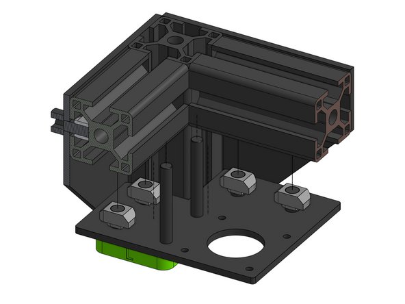
Thread the two Cap Head Screw M5x40 and two Cap Head Screw M6x12 screws through the motor_support_l part
-
The motor_support_l part is supposed to hold the screw heads tightly
-
Thread the support assembly through the motor_plate along with the remaining two Cap Head Screw M6x12 screws
-
Attach the 3030 M6 T-nuts. Don't tighten fully yet.
-
-
-
Repeat the previous step for the right side with the use of motor_support_r part
-
-
-
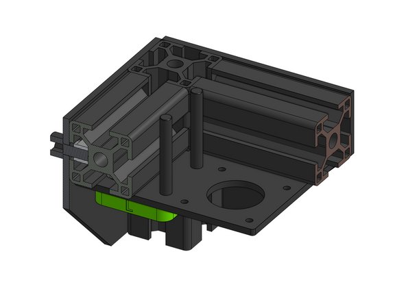
Attach the left drive base to the left top corner of the printer
-
Make sure the plate is in the corner and tighten the M6 screws to lock the T-Nuts in place
-
The T-Nuts need to rotate within the 3030 extrusion for a secure attachment
-
-
-
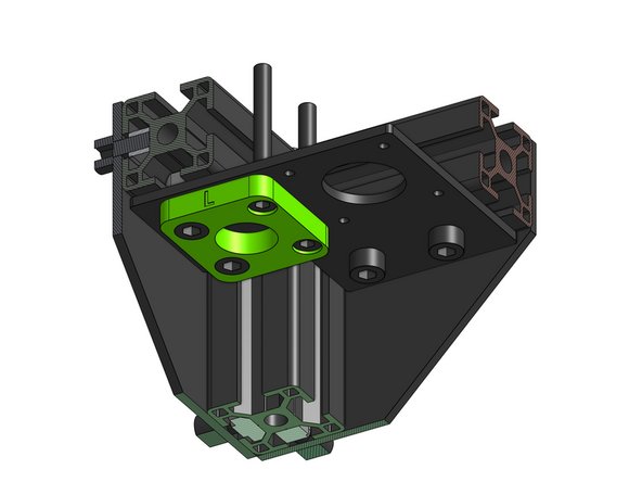
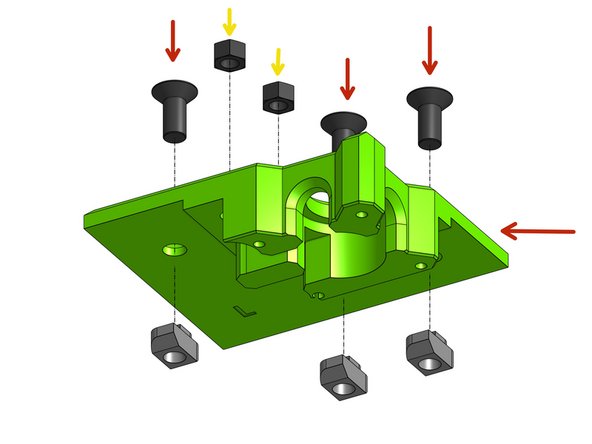
The three Countersink Screw M6x14 (the countersunk ones) and thread those through the xy_motor_cage_top_left printed part
-
Attach the 3030 M6 T-nuts, don't tighten fully
-
Pull the M5 Hex Locking Nuts into place with the nut pull technique (described in the Preparations guide)
-
Repeat on the xy_motor_cage_top_right part
-
-
-
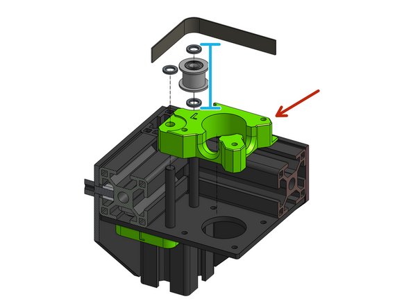
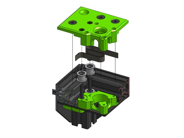
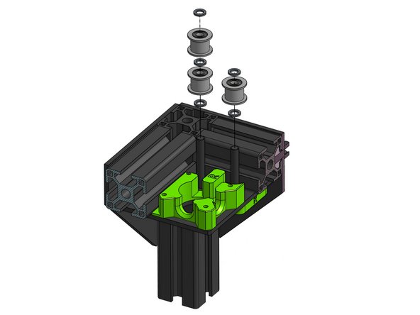
Slide the xy_motor_cage_bottom_left part onto the M5 screws
-
Add one precision shim on the M5 screw going through the printed part and shim, idler, shim on the second M5 screw
-
Put the belt in, flat side on the idler, leave the ends of the belt hanging loose
-
-
-
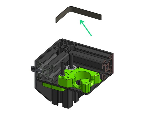
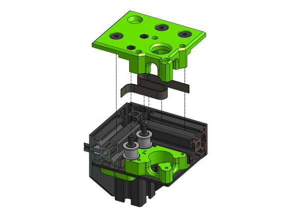
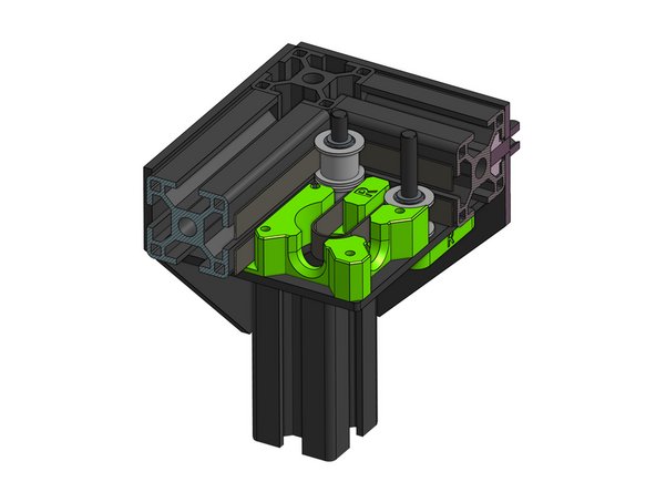
Side one smooth idler on each of the two M5 screws, add shims on top of them
-
Fold the top belt over the idlers, smooth side on the idler
-
Leave a large loose loop on the top belt - you will need to thread the motor pulley through it later on
-
-
-
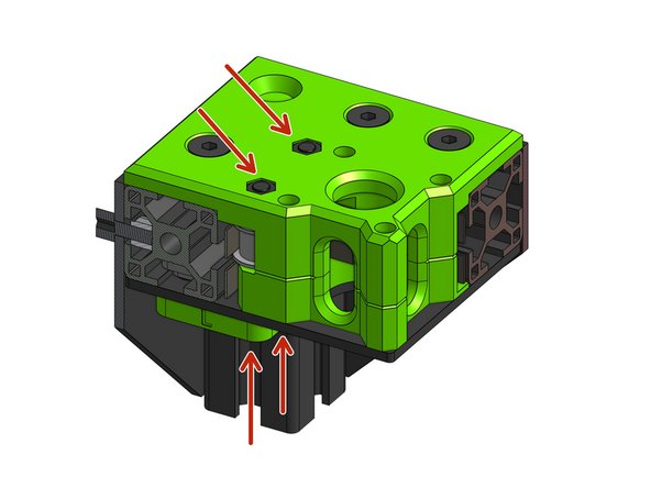
Place the top part on the assembly and fasten it with the M5 screws from underneath. The parts need to be flush but not so tight that they'll stop the idlers from rotating
-
Do not over tighten or you will be compressing the bearings.
-
Fasten the Countersink Screws at the top - remember that the T-Nuts inside need to rotate and grab the inside of the 3030 extrusion
-
-
-
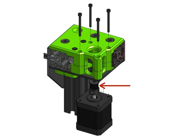
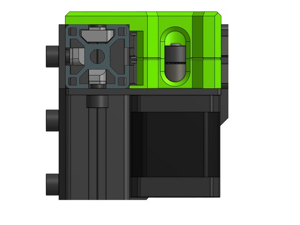
Put the motor pulley on the motor shaft with the teeth oriented up
-
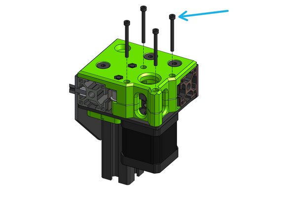
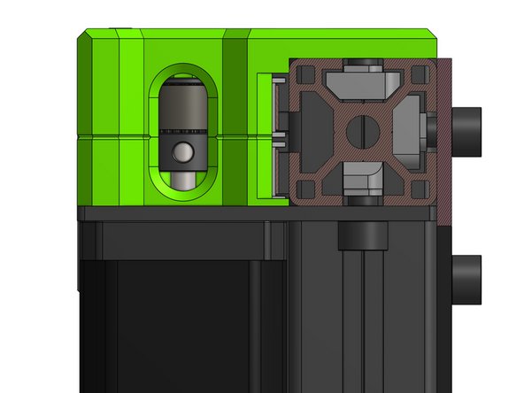
Attach the motor to the assembly with four Cap Head Screws M3x35. The motor pulley needs to get into the belt loop you left loose on the previous step
-
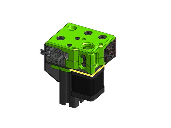
Make sure the motor is sitting flush against the plate
-
-
-
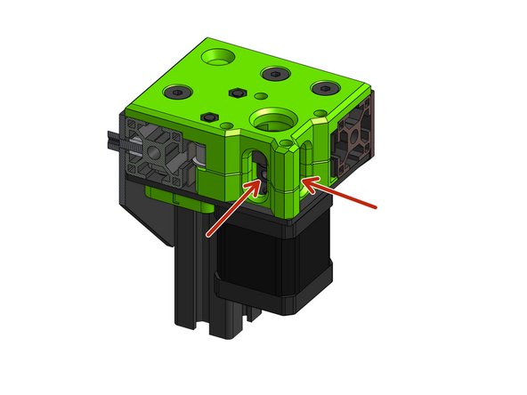
This is one of the most important steps in the whole manual - failure to align the belts will result in rubbing and belt failure!
-
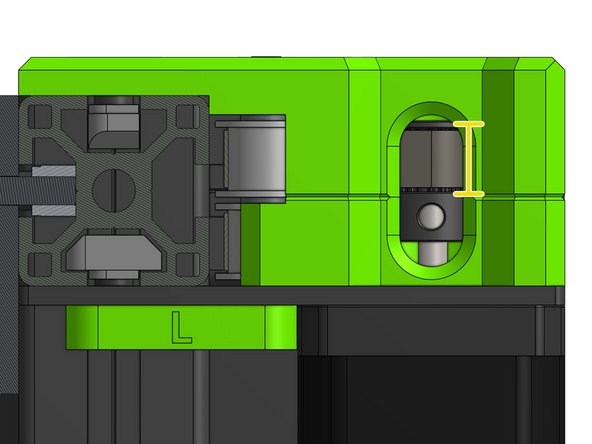
Tighten the belt to remove the loose belt loop we left in the previous steps. Align the pulley to see both pulley grub screws through the openings in the printed parts
-
Make sure the belt is in the middle of the pulley
-
Tighten the grub screws on the pulley. One of the set screws should be in contact with the flat side of the motor shaft
-
-
-
The right motor drive is very similar to the left one with the difference that the bottom belt is driven so there are two idlers at the bottom and one on top
-
Attach the motor plate with the motor_support_r part and corresponding screws and nuts
-
Place the xy_cage_bottom printed part on the motor plate and thread the five shims with 3 smooth idlers on the M5 screws
-
Attach the top part
-
Do not over tighten or you will be compressing the bearings.
-
Unlike the in the left drive the pulley on the right drive has it's teeth downwards
-
-
-
As with the left motor this is a crucial step!
-
Ensure the belt pulley is aligned properly with the belt once you pull the belt loop back
-
Tighten the pulley motor screws
-


Cancel: I did not complete this guide.
50 other people completed this guide.
