
Video Overview
-
-
y_belt_mount printed part
-
3x M5 Nylon Locking Hex Nut
-
4x M3 Nylon Locking Hex Nut
-
2x M3x25 Cap Head Screw
-
2x M3x16 Cap Head Screw
-
y_belt_cover printed part
-
650mm 2GT 9mm Wide Timing Belt
-
-
-
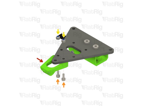
y_belt_mount printed part
-
M5 Nylon Locking Hex Nut
-
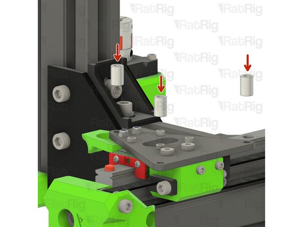
Insert both of the M5 nylon lock nuts into the printed part as shown
-
Insert all four M3 nylon lock nuts into the printed part as shown
-
-
-
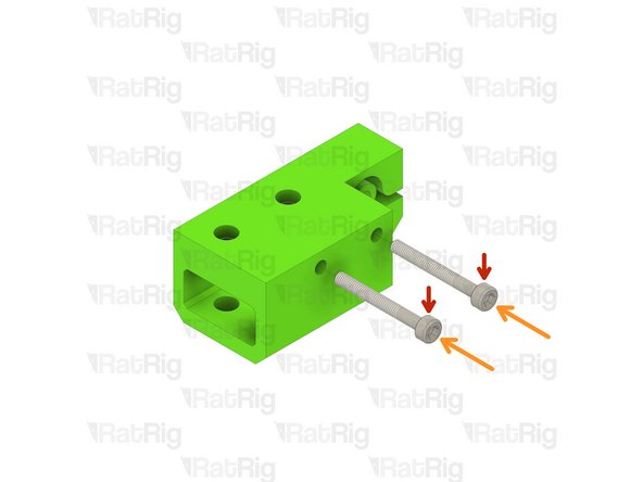
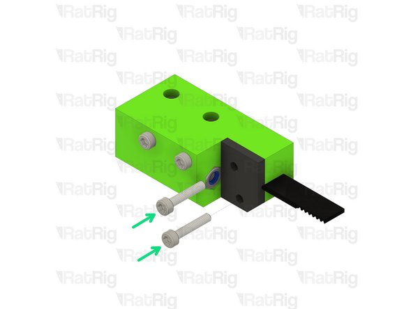
M3x25 Cap Head Screw
-
Fasten the M3x25 screws through the y_belt_mount printed part
-
Take care not to over tighten the M3x25 screws as you can damage the printed part
-
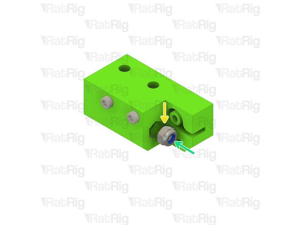
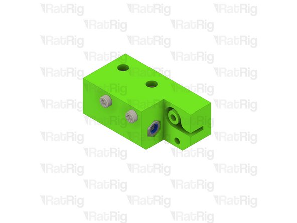
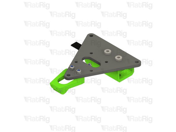
M5 Nylon Locking Hex Nut
-
Insert the M5 nylon lock nut into the printed part as shown
-
-
-
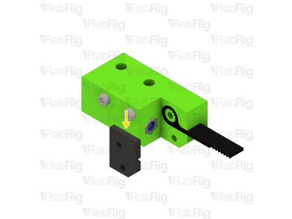
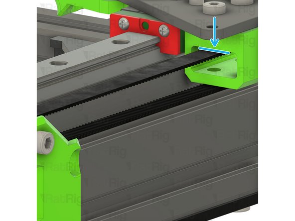
650mm 2GT 9mm Wide Timing Belt
-
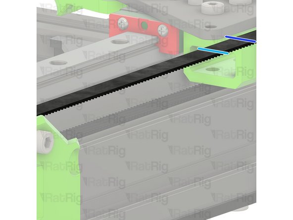
Take one end of the belt and fold it back on itself so that the teeth lock together and form a loop
-
Insert the belt loop into the y_belt_mount as shown
-
y_belt_cover printed part
-
M3x16 Cap Head Screw
-
Place the y_belt_cover as shown and secure it in place with the two M3x16 screws
-
Take care not to over tighten the M3x16 screws as you can damage the printed parts
-
Set this assembly aside until Step 6
-
-
-
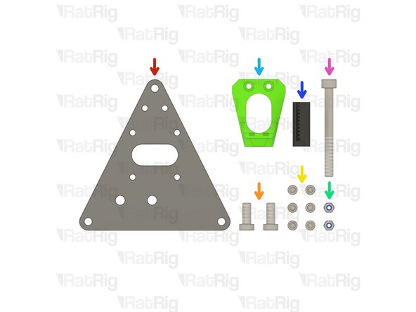
1x V-Minion Sub Plate
-
2x M5x12 Low-Head Cap Screw
-
6x M3x8 Cap Head Screw
-
2x M3 Nylon Locking Hex Nut
-
bed_wire_guide_start printed part
-
y_belt_tensioner printed part
-
1x M5x50 Cap Head Screw
-
-
-
Assembly from Step 4
-
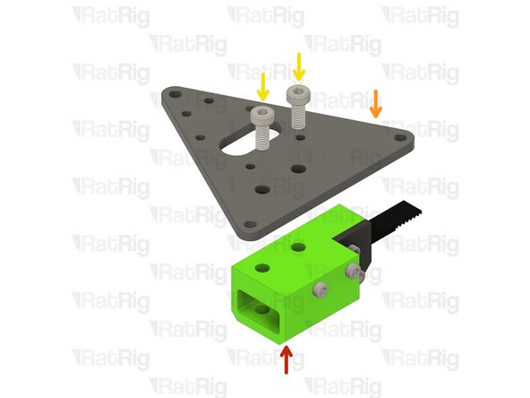
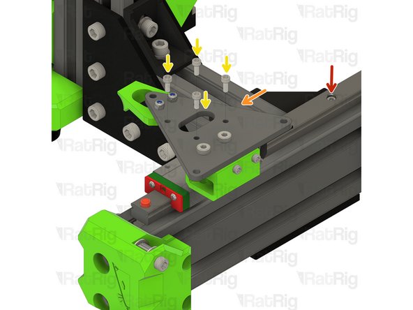
V-Minion Sub Plate
-
Note that the V-Minion Sub Plate is not symmetric. Make sure it is oriented as shown, otherwise you will encounter assembly issues further in the guide
-
M5x12 Thin-Head Cap Screw
-
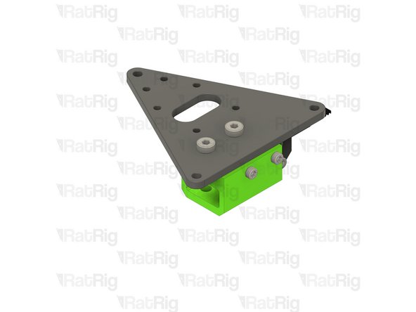
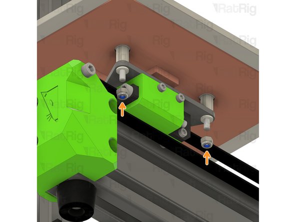
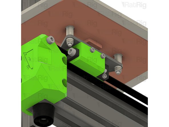
Fasten the y_belt_mount to the V-Minion sub plate by using the M5x12 screws
-
Take care not to over tighten the M5x12 screws as you can damage the printed parts
-
-
-
bed_wire_guide_start printed part
-
M3x8 Cap Head Screw
-
M3 Nylon Locking Hex Nut
-
Fasten the bed_wire_guide_start printed part to the V-Minion sub plate assembly using the two M3x8 screws
-
Take care not to over tighten the M3x8 screws as you can damage the printed part
-
-
-
V-Minion Frame Assembly
-
V-Minion Y-Axis Carriage Assembly from Step 7
-
M3x8 Cap Head Screw
-
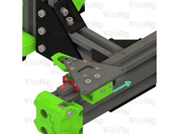
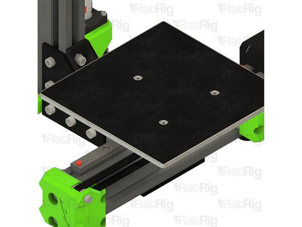
Align the Y-axis carriage assembly with the Y-axis linear rail carriage and fasten securely using the four M3x8 screws
-
Do not over tighten the M3x8 screws as they can cause the V-Minion sub plate to twist and not be flat. This will cause issues with the print bed not being level
-
Slide the assembled Y-axis up and down the rail to make sure it moves smoothly
-
If the assembly binds at all, slightly loosen the M3x8 screws and check again
-
-
-
Take the free end of the timing belt and feed it around the stepper motor pulley
-
Continue along the underside of the Y-axis
-
Feed it around the Y-axis idler pulley...
-
...and continue back to the Y-axis carriage
-
Pull the belt and mark where it meets the Y-axis carriage. This can be with a marker, or simply by holding it.
-
Measure 16mm, or count 8 teeth on the belt, from the position marked previously. Double check your measurements and then cut the belt at this point
-
The belt can be cut with regular scissors.
-
It is better to cut the belt too long than too short! If you are unsure, cut it longer than expected, you can always remove more if needed
-
-
-
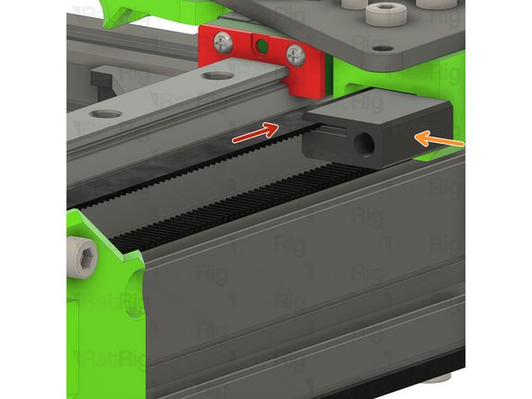
Cut end of 2GT 9mm timing belt
-
y_belt_tensioner printed part
-
Insert the end of the belt into the printed part as shown
-
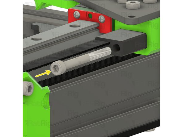
M5x50 Cap Head Screw
-
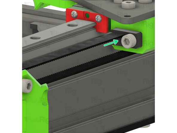
Insert the M5x50 screw through the y_belt_tensioner printed part and into the y_belt_mount.
-
You can now adjust the tension of the Y-axis belt:
-
Tighten the M5x50 screw to increase belt tension
-
Loosen the M5x50 screw to decrease belt tension
-
-
-
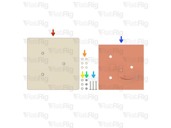
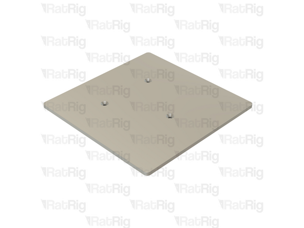
1x V-Minion Cast Bed Plate
-
6x M4 Nylon Washer
-
3x Stainless Steel Spacer
-
3x M4 Nylon Locking Hex Nut
-
3x M4x30 Countersunk Hex Head Screw
-
1x 180x180mm 24v Silicone Heater
-
-
-
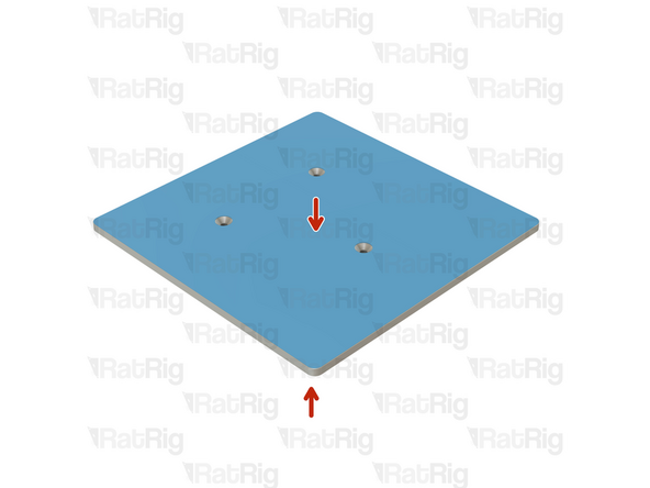
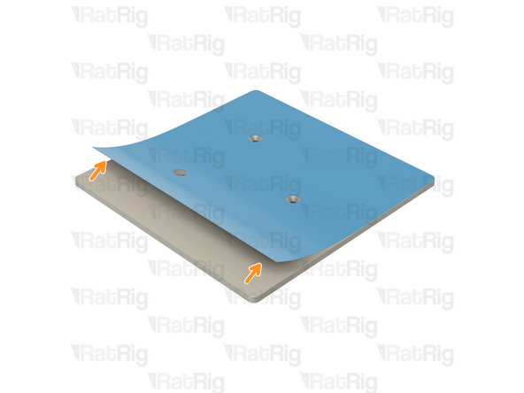
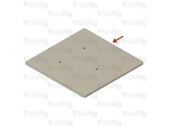
To prevent scratches, the bed plate is shipped with a protective film on both sides.
-
Gently peel off the protective film.
-
Repeat for the other side.
-
-
-
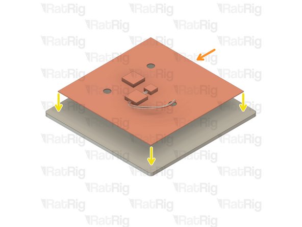
Take your time when performing this step as the heater pad cannot be removed or repositioned. Once any part of the heater pad is placed, do not try to move or remove it under any circumstances.
-
V-Minion Cast Bed Plate
-
180x180mm 24v Silicone Heater
-
Peel back roughly one inch of the protective sheet along a single side of the heater pad. Position the heater pad centrally on bottom of the aluminium bed and press down, adhering the edge of the heater to the bed.
-
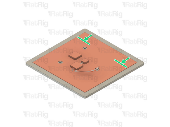
Working gradually, peel the protective sheet, and adhere the rest of the heater to the aluminium bed.
-
Make sure no air bubbles are trapped under the silicone heater as this can lead to damage and failure of the heater
-
-
-
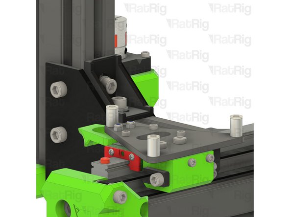
Stainless Steel Spacer
-
Place one spacer on each corner of the V-Minion sub plate as shown...
-
M4 Nylon Washer
-
...and then place a nylon washer atop each spacer
-
-
-
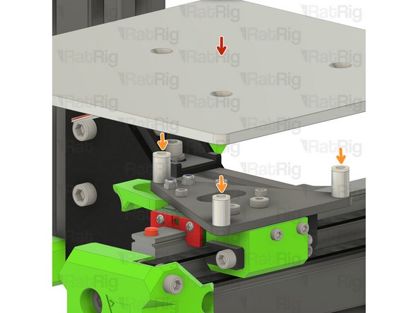
V-Minion Cast Bed Plate
-
Carefully place the V-Minion bed plate onto the spacer and washer stacks as shown
-
M4x30 Countersunk Hex Head Screw
-
In each of the three holes in the bed, insert one M4x30 screw. It should pass through the bed, washer, spacer and sub plate as shown
-
-
-
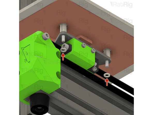
M4 Nylon Washer
-
M4 Nylon Locking Hex Nut
-
Install an M4 nylon washer and M4 nylon locking nut to each M4x30 screw as shown. Do not tighten them fully yet
-
-
-
M4 Nylon Washer
-
M4 Nylon Locking Hex Nut
-
Install an M4 nylon washer and M4 nylon locking nut to the remaining M4x30 screw as shown. You will fully tighten them in the next step
-
-
-
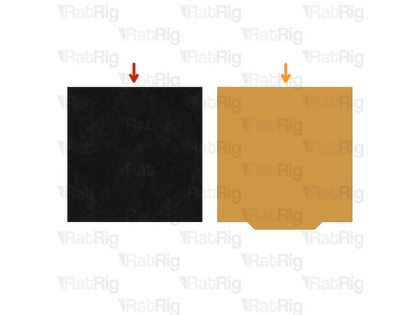
The print surface comes in two pieces:
-
1x 180x180 magnetic sheet with self-adhesive backing
-
1x PEI powder-coated flex plate print surface
-
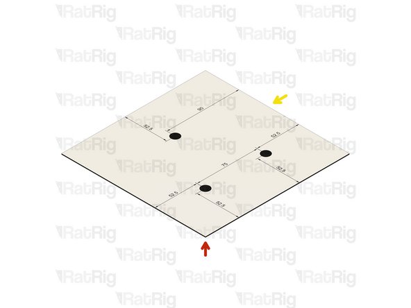
Once the magnetic sheet is installed, the M4x30 screws securing the bed become inaccessible. For this reason, it is recommended to cut three holes into the magnetic sheet prior to installation.
-
A printable template is available to assist in locating where to cut the holes in the magnetic sheet. Click here to download it
-
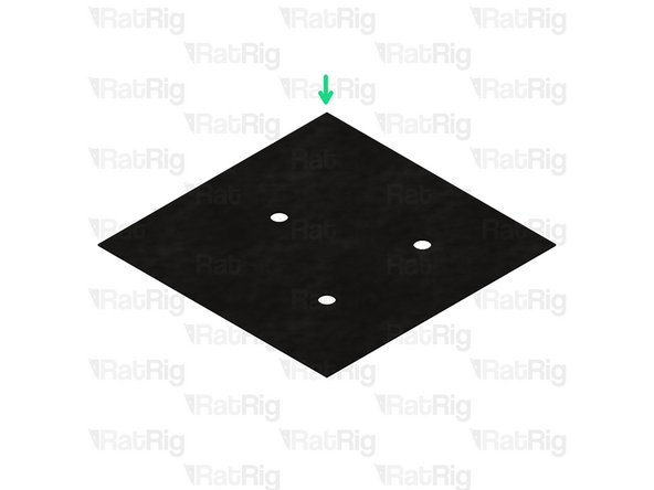
Magnetic sheet with holes cut out
-
Alternately, the magnetic sheet can be set aside until the V-Minion assembly is completed. This allows the bed mesh to be verified prior to covering the M4x30 screws
-
-
-
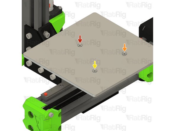
Tighten the bed screws, half of a turn at a time, in a clockwise order:
-
First
-
Second
-
Third
-
Repeat the sequence until all three M4x30 screws are tight
-
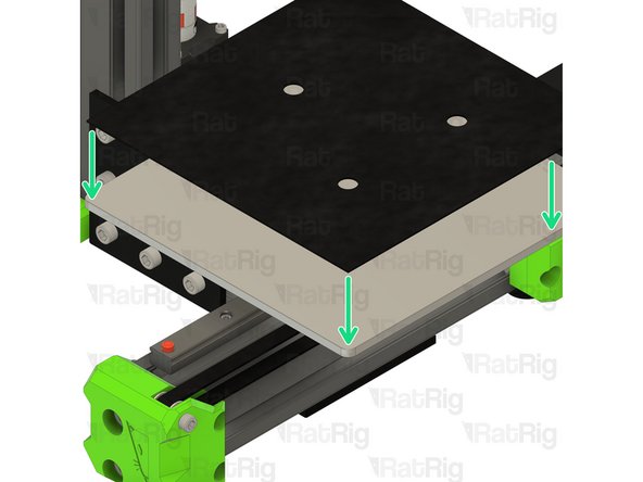
Separate the magnetic sheet from the PEI flex print surface. Set the print surface aside until the V-Minion is assembled
-
Remove the adhesive backing from the magnetic bed sheet and apply it to the bed plate as shown
-
Make sure no air bubbles are trapped under the magnetic sheet as this will cause the print surface to be uneven
-
-
-
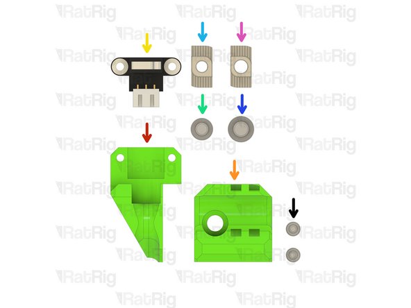
y_endstop_mount printed part
-
bed_wire_guide_end printed part
-
1x Endstop
-
1x M5x12 Cap Head Screw
-
1x 3030 Drop-in T-Nut - M5
-
1x M6x12 Cap Head Screw
-
1x 3030 Drop-in T-Nut - M6
-
2x M3x8 Cap Head Screw
-
-
-
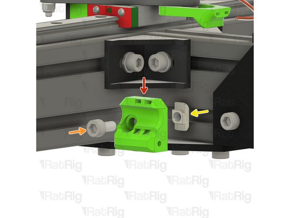
bed_wire_guide_end printed part
-
M6x12 Cap Head Screw
-
3030 Drop-in T-Nut - M6
-
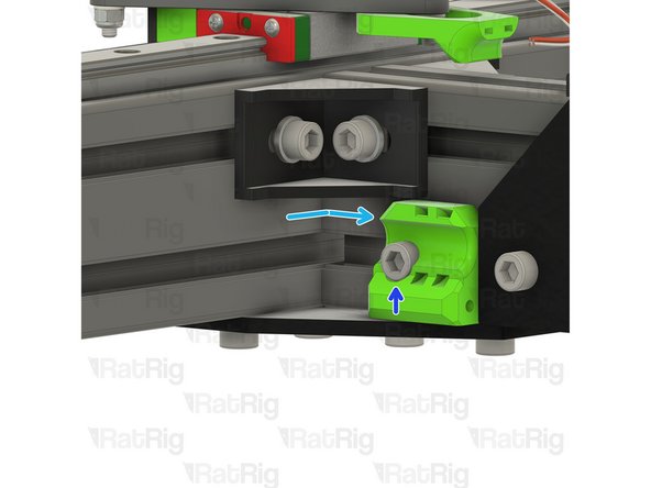
Insert the M6x12 screw into the bed_wire_guide_end printed part
-
Loosely thread the 3030 T-Nut onto the M6x12 screw. Do not tighten it at this point
-
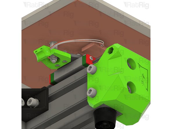
Fit the wire guide assembly to the frame as shown
-
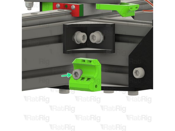
Fasten the M6x12 screw
-
Take care not to over tighten the M6x12 screw as you can damage the printed part
-
-
-
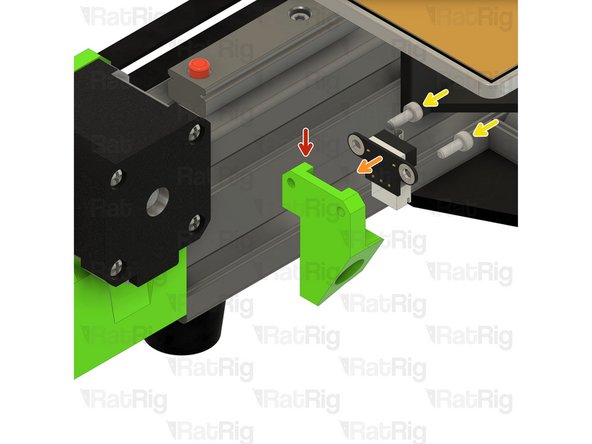
y_endstop_mount printed part
-
Endstop. Install the endstop cable before fastening to the printed part
-
M3x8 Cap Head Screw
-
Secure the endstop to the mount with two M3x8 screws as shown
-
Take care not to over tighten the M3x8 screws as you can damage the printed part
-
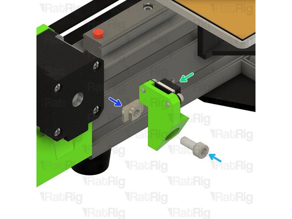
Insert the M5x12 screw into the y_endstop_mount printed part
-
Loosely thread the 3030 T-Nut onto the M5x12 screw. Do not tighten it at this point
-
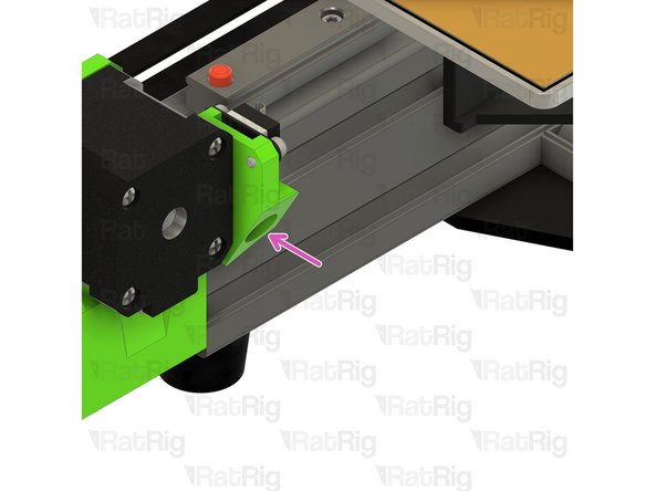
Fit the endstop assembly to the frame as shown by fastening the M5x12 screw
-


Cancel: I did not complete this guide.
17 other people completed this guide.