
Steps
45
- 10. EVA 3.0 Hex Nut Assembly 45 steps

User-Contributed Guide
This guide is not managed by the site's staff.
Quiz
0
Introduction
This guide covers the assembly of the EVA 3.0 print head. Whilst EVA 3.0 supports multiple combinations of extruder, hot end, and cooling, this guide focuses on the components supplied in the default V-Core 3.1 kit:
- Bondtech LGX Lite extruder
- Phaetus Rapido HF hot end
- 4028 part cooling fan
- Rat Rig “SuperPinda” Probe by P&F
Information regarding other component combinations can be found on the EVA website
-
-
1x Bondtech LGX Lite Extruder
-
1x EVA3 back_core_xy Printed Part
-
1x EVA3 drive_lgx_lite Printed Part
-
1x EVA3 front_universal Printed Part
-
4x Flat Square Nut - M3
-
1x EVA3 top_endstop_mgn12c Printed Part
-
18x Hex Nut - M3
-
4x M3x8 Cap Head Screw
-
-
-
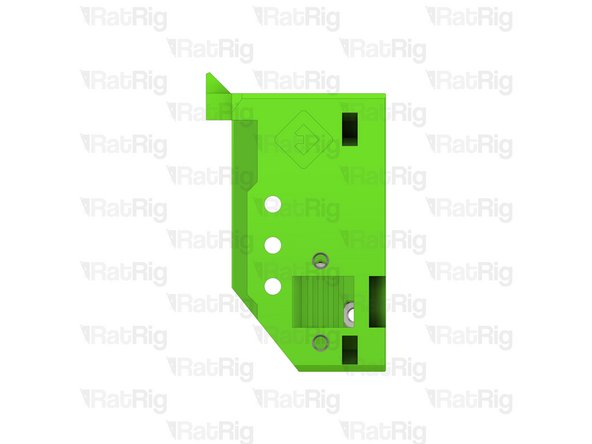
EVA3 top_endstop_mgn12c Printed Part
-
Hex Nut - M3
-
Install an M3 hex nut into each of the three positions shown
-
Set this assembly aside until Step 14
If you have round holes instead of hexagonal, you are using the wrong tutorial, jump to the next chapter: 10. EVA 3.0 Heat Insert Assembly
Andrei Macaveiu - Resolved on Release Reply
-
-
-
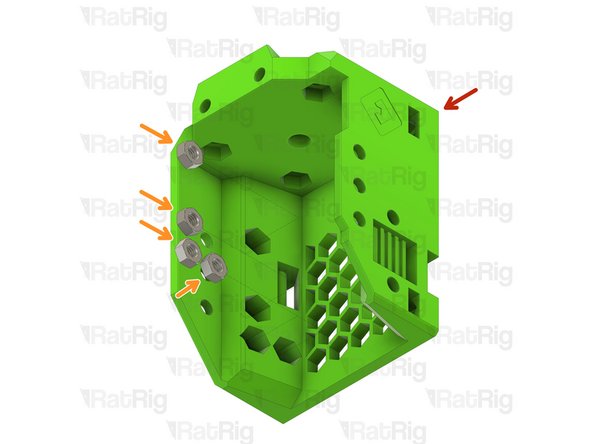
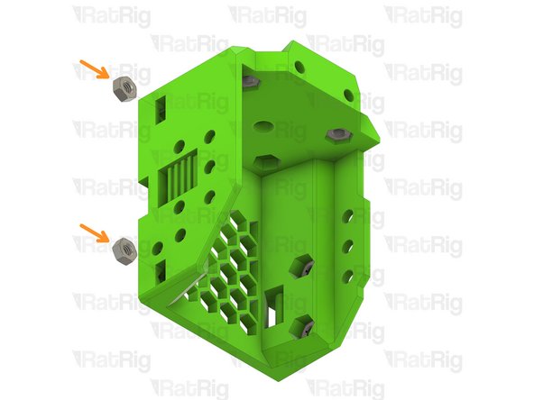
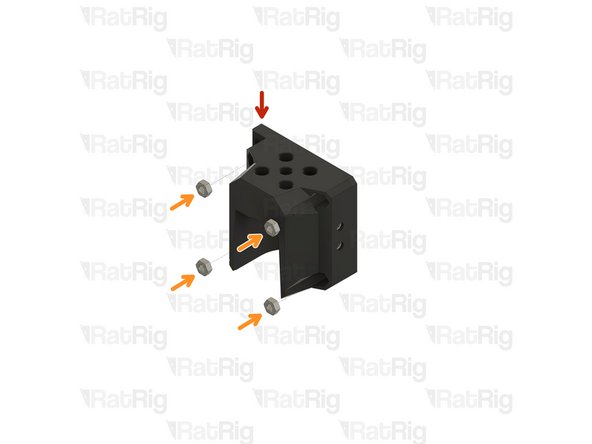
EVA3 universal_front Printed Part
-
Hex Nut - M3
-
Install an M3 hex nut into each position shown, there should be four on the left and two in the top
Be VERY carefull with this part; I got the printed parts set and some tolerances are too lose (nuts keep dropping out and one is just shredding plastic as it turns around freely) and others were so tight the screw went in instead of pulling the nut in. Make sure to place the part flat down when you have to insert nuts so they can't rotate/tilt and get stuck. The safest way to get them straight in is to use a bolt to pull them in, otherwise you risk threading the bolts in wrong and then you are screwed.
Roodkpvoske - Resolved on Release Reply
-
-
-
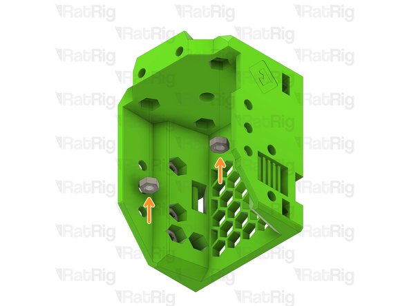
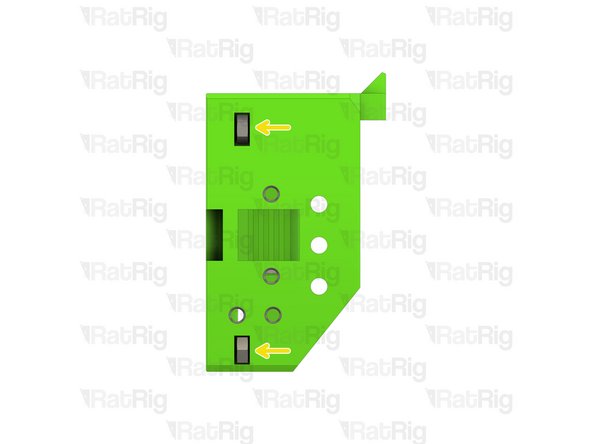
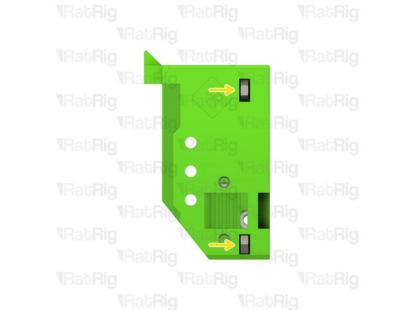
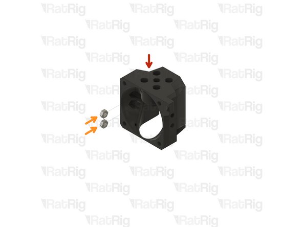
EVA3 universal_front Printed Part
-
Hex Nut - M3
-
Install an M3 hex nut into each position as shown
-
The M3 hex nuts inserted into the side slots must be pulled into position using an M3 cap head screw
-
-
-
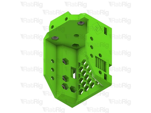
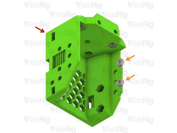
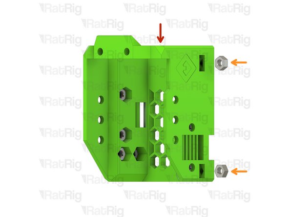
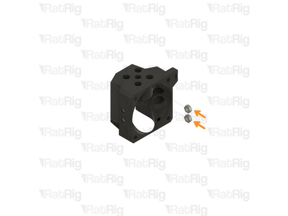
EVA3 universal_front Printed Part
-
Hex Nut - M3
-
Install an M3 hex nut into each position as shown
-
The M3 hex nuts inserted into the side slots must be pulled into position using an M3 cap head screw
-
Set this assembly aside until Step 16
-
-
-
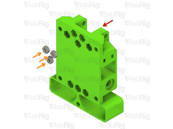
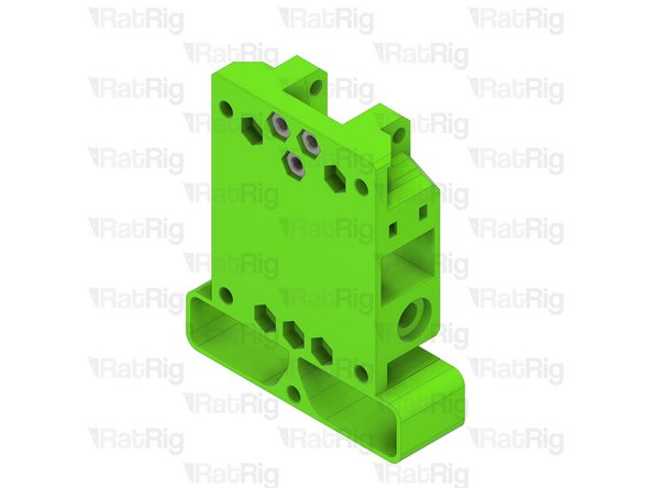
EVA3 back_core_xy Printed Part
-
Hex Nut - M3
-
Install an M3 hex nut into each of the three positions shown
-
Set this assembly aside until Step 15
-
-
-
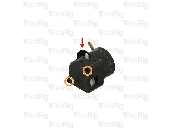
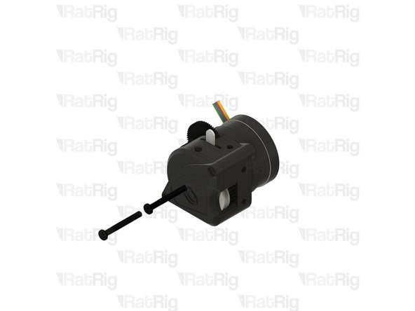
Bondtech LGX Lite extruder
-
Remove the two M3x25 screws holding the Bondtech LGX Lite together
-
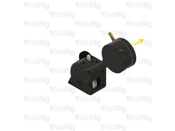
Carefully remove the motor from the LGX Lite assembly
-
Set the LGX Lite motor aside until Step 26
-
-
-
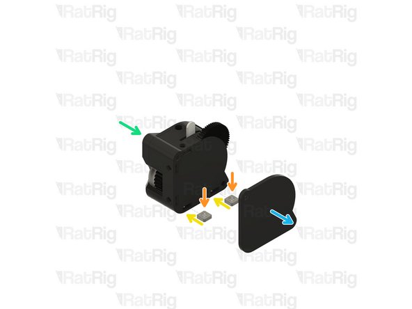
Carefully remove the face plate from the LGX Lite assembly
-
M3 Square Nut
-
Insert one M3 square nut into each of the marked holes on the LGX Lite
-
Re-install the LGX Lite face plate
-
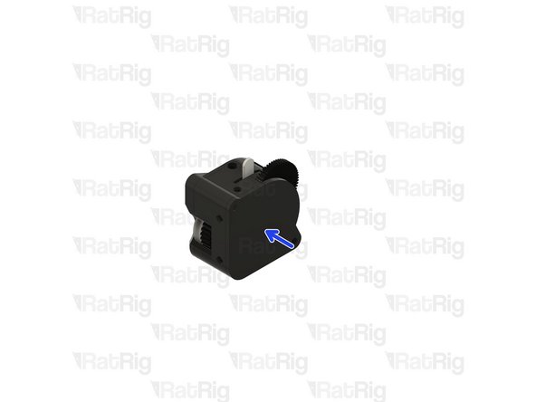
Carefully remove the rear plate from the LGX Lite assembly
-
Insert one M3 square nut into each of the marked holes on the LGX Lite
-
Re-install the LGX Lite back plate
-
-
-
Bondtech LGX Lite assembly
-
EVA3 drive_lgx_lite Printed Part
-
M3x8 Cap Head Screw
-
Install an M3x8 screw into each of the four positions shown. This will secure the LGX Lite extruder to the printed part
-
Take care not to over tighten the M3 screws as you can damage the printed part or the LGX Lite
-
Re-install the two M3x25 screws into the LGX Lite extruder
The 2 screws just sit there to hold th3 extruder together. The nuts are in the motor
Donald Fast - Resolved on Release Reply
-
-
-
1x EVA3 bottom_horns Printed Part
-
4x M3x35 Cap Head Screw
-
4x M2.5x8 Cap Head Screw (Included with the Phaetus Rapido HF)
-
1x EVA3 hotend_rapido Printed Part
-
1x Phaetus Rapido HF Hotend
-
Follow the included assembly instructions to prepare the Rapido HF for use. The groovemount adapter which is pre-installed must be removed for use on EVA3
-
8x Hex Nut - M3
-
1x 43.7mm PTFE Tube
-
-
-
EVA3 hotend_rapido Printed Part
-
Hex Nut - M3
-
Install an M3 hex nut into each position as shown
-
-
-
EVA3 hotend_rapido Printed Part
-
Hex Nut - M3
-
Install an M3 hex nut into the four positions as shown
-
-
-
Assembly from the previous step
-
M2.5x8 Cap Head Screw
-
Phaetus Rapido HF assembly
-
Insert the four M2.5x8 screws through the printed part and fasten them into the Rapido HF hotend
-
43.7mm PTFE Tube
-
Insert the PTFE tube as shown, ensure it is fully pushed down into the hotend
-
Set this assembly aside until Step 30
And the answer is : the cable faces the large opening where the fan goes
Donald Fast - Resolved on Release Reply
-
-
-
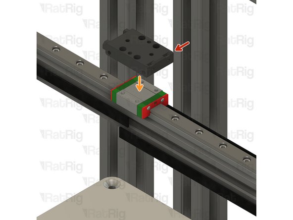
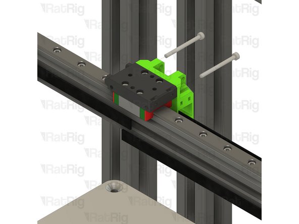
Assembly from Step 2
-
Place the EVA3 top assembly atop the MGN12 carriage as shown
-
Make sure the holes on the side of the printed part face towards the left of the x-axis
-
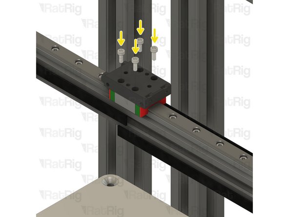
M3x8 Cap Head Screw
-
Fasten all four M3x8 screws to secure the EVA3 top assembly to the MGN12 carriage
-
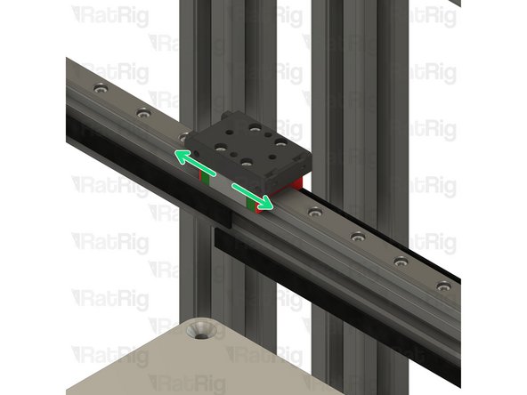
Slide the X-axis left and right along the rail to make sure it moves smoothly
-
If the carriage binds at all, slightly loosen the M3x8 screws and check again
-
-
-
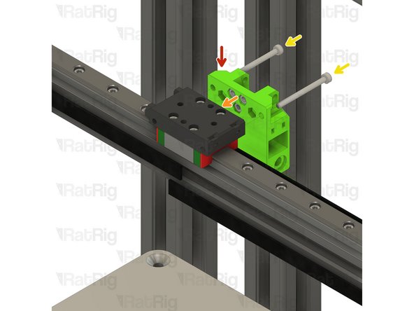
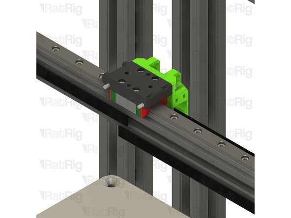
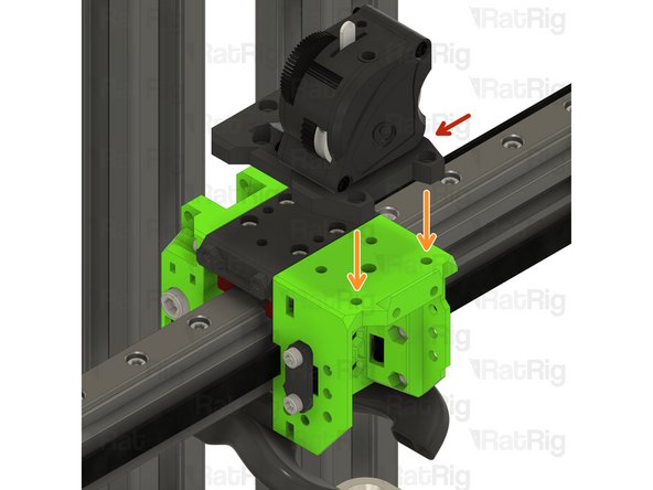
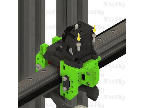
EVA3 back assembly from Step 6
-
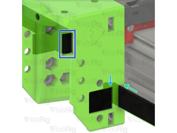
Position the EVA3 back assembly as shown
-
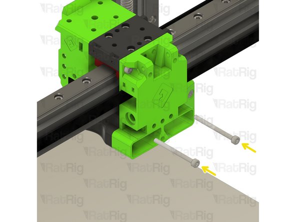
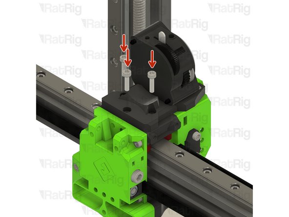
M3x35 Cap Head Screw
-
Insert the M3x35 screws through the EVA3 back assembly and into the MGN12 mount as shown
-
-
-
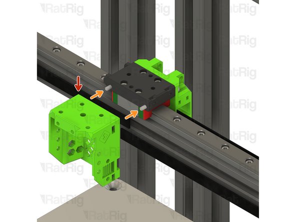
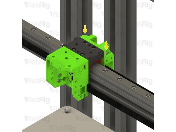
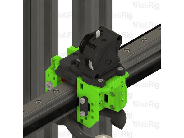
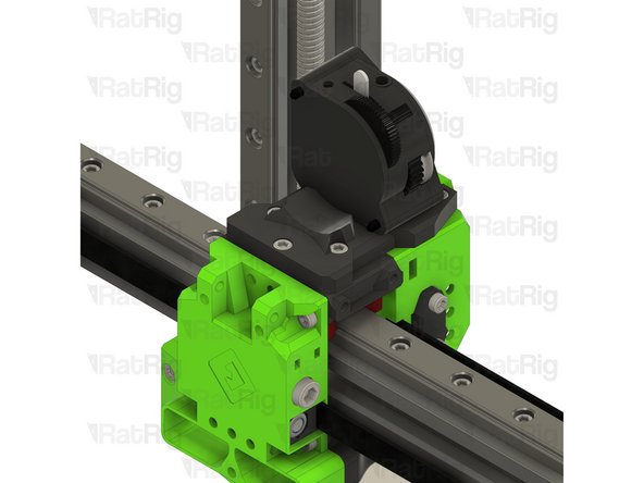
EVA3 front assembly from Step 5
-
Position the EVA3 front assembly as shown
-
Tighten the M3x35 screws to secure the EVA3 front assembly to the x-axis carriage
-
Take care not to over tighten the M3 screws as you can damage the printed parts
-
Take the end of the lower CoreXY belt and pass it through the side of the EVA3 front as shown
-
Pass the belt back out using the shown slot
-
Repeat these steps for the top CoreXY belt
-
The ends of both of these belts will be secured in Step 19
I suggest to fix the belts in the opposite order: first install them in the belt grabbers (Step 21 & 22) and attach them loosely to the EVA3 back part.
After you have done that, attach them to the EVA3 front part as shown in Step 17.
This way you don't need to cut the belts at this point. You can instead leave them hanging from the EVA3 front part until you are sure how much tension to apply and then cut them off.
-
-
-
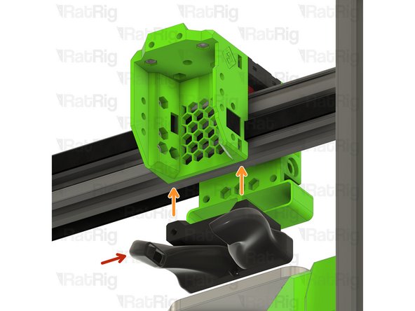
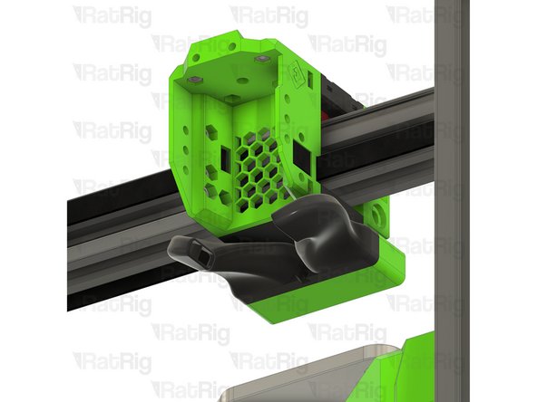
EVA3 bottom_horns_volcano Printed Part
-
Position the EVA3 bottom as shown
-
M3x35 Cap Head Screw
-
Install each M3x35 screw into the back, through the EVA3 bottom and secure them into the EVA3 front
-
Take care not to over tighten the M3 screws as you can damage the printed parts
-
-
-
2x EVA3 core_xy_belt_grabber Printed Part
-
3x M3x12 Cap Head Screw
-
2x M5 Nylon Locking Hex Nut
-
2x EVA3 face_belt_grabber Printed Part
-
6x M3x8 Cap Head Screw
-
2x M5x40 Cap Head Screw
-
-
-
Check that the CoreXY belt is still positioned from Step 16
-
Place the EVA3 face_belt_grabber printed part over the exposed belt end
-
Fasten two M3x8 screws through the EVA3 face_belt_grabber and into the universal face
-
Repeat the process on the left side of the EVA3 assembly
-
Take care not to over tighten the M3 screws as you can damage the printed parts
If you follow the guide step by step, the belts are already in the correct orientation after installing the Left and Right Motors. For reference, the teeth of the belt face outward (towards the printed face_belt_grabber).
-
-
-
Loose end of the lower CoreXY belt
-
Mark the belt where it meets the EVA3 assembly. This can be with a marker, or simply by holding it.
-
From the mark, towards the loose end of the belt, measure 24mm (or count 12 teeth)
-
It is better to cut the belt too long than too short! If you are unsure, cut it longer than expected, you can always remove more if needed
-
Double check your measurements and then cut the belt at this point
-
Insert the cut end of the belt into the core_xy_belt_grabber printed part
-
Insert an M5 nylon locking nut into the core_xy_belt_grabber as shown
-
Insert the core_xy_belt_grabber assembly into the EVA3 assembly as shown
I disagree with this, don't leave your belts any longer! I did so, thinking it would be easily adjusted afterwards, but if the belt grabber reaches the end of the EVA3 assembly during tensioning it will get very stuck (as in the belt ripped out and it still didn't budge stuck). Prevent this by cutting the belts short enough beforehand.
Roodkpvoske - Resolved on Release Reply
-
-
-
M5x40 Cap Head Screw
-
Insert the M5x40 screw into the marked hole on the EVA3 assembly and fasten it slightly to engage with the M5 nylon locking nut
-
Do not tighten the M5x40 screw at this point. The belts will be tensioned correctly in a later guide
I've broken (3) belt grabbers trying to get the 5mm locking hex nut to pull into its cavity. I succeeded with ONE. Printing more now :(((
Mike Schoonmaker - Resolved on Release Reply
-
-
-
Loose end of the upper CoreXY belt
-
As in Step 20, mark the belt where it meets the EVA3 assembly. This can be with a marker, or simply by holding it.
-
From the mark, towards the loose end of the belt, measure 24mm (or count 12 teeth)
-
It is better to cut the belt too long than too short! If you are unsure, cut it longer than expected, you can always remove more if needed
-
Double check your measurements and then cut the belt at this point
-
Insert the cut end of the belt into the core_xy_belt_grabber printed part
-
Insert an M5 nylon locking nut into the core_xy_belt_grabber as shown
-
Insert the core_xy_belt_grabber assembly into the EVA3 assembly as shown
-
-
-
M5x40 Cap Head Screw
-
Insert the M5x40 screw into the marked hole on the EVA3 assembly and fasten it slightly to engage with the M5 nylon locking nut
-
The M5x40mm screws are used to tighten the CoreXY belts
-
Tighten each M5x40 screw one-half turn at a time to tension the belts equally
-
Continue tightening the screws until the belts are no longer slack
-
Check that the X-axis gantry is square by moving it to the front of the machine. If it has skewed, it can be squared by adjusting the tension of one belt at a time
-
Make sure not to over-tension the belts as this can cause damage to the bearings, the belt, the motors or printed parts!
-
An excellent article on correct CoreXY belt tensioning is available on Mark Rehorst's website
-
-
-
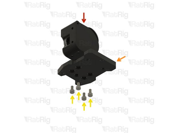
Bondtech LGX Lite assembly from Step 9
-
Place the Bondtech LGX Lite assembly onto the top of the EVA3 assembly as shown
-
M3x8 Cap Head Screw
-
Fasten the two M3x8 screws through the drive_lgx_lite printed part into the EVA3 universal front
-
Take care not to over tighten the M3 screws as you can damage the printed parts
-
-
-
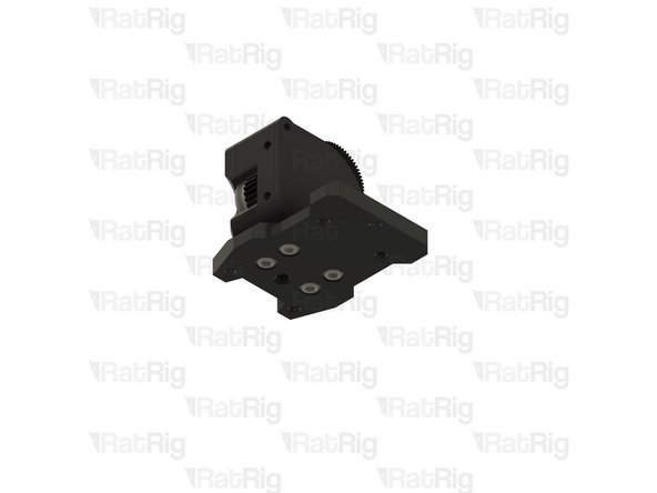
M3x12 Cap Head Screw
-
Fasten the three M3x12 screws through the drive_lgx_lite printed part into the EVA3 universal front
-
-
-
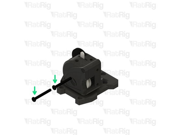
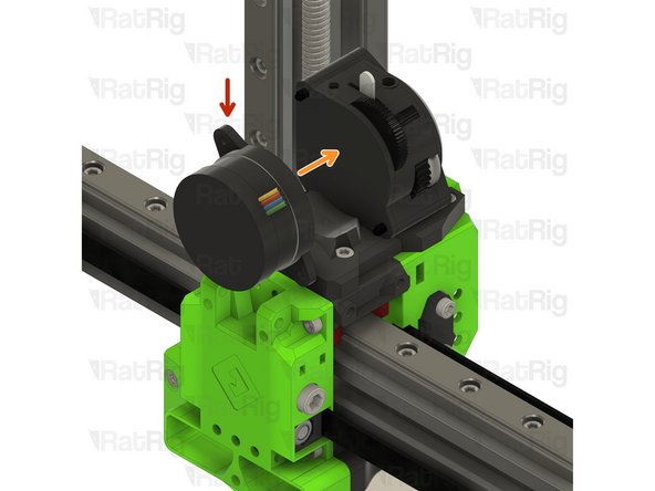
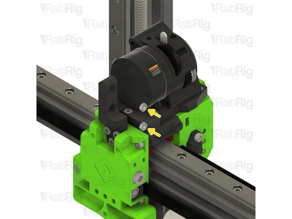
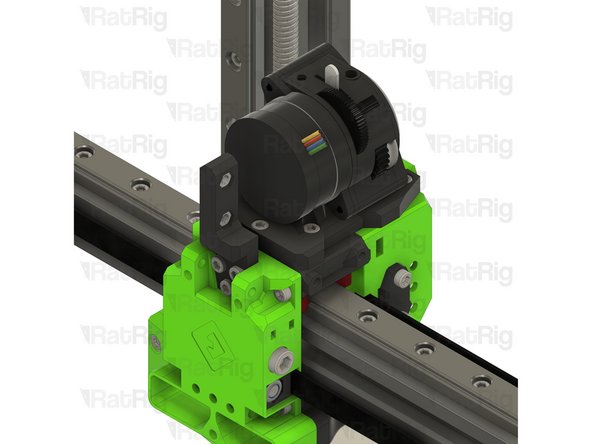
Bondtech LGX Lite motor from Step 7
-
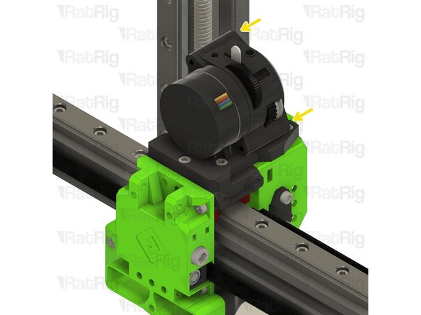
Re-install the Bondtech LGX Lite motor into the back of the LGX Lite extruder
-
Fasten the two M3x25 screws on the face of the LGX Lite to secure the motor in place
-
-
-
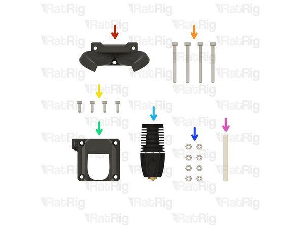
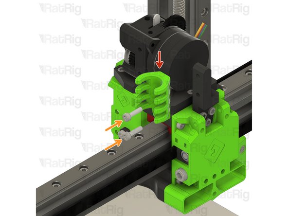
1x EVA3 cable_guide Printed Part
-
2x M3x12 Cap Head Screw
-
2x Hex Nut - M3
-
1x ratrig_eva3_shroud Printed Part
-
1x EVA3 cable_guide_mount Printed Part
-
9x M3x8 Cap Head Screw
-
1x 40x10mm 24V Axial Fan
-
4x M3x20 Cap Head Screw
-
-
-
EVA3 cable_guide_mount Printed Part
-
M3x8 Cap Head Screw
-
Fasten the three M3x8 screws through the EVA3 cable_guide_mount printed part and into the EVA3 back
-
Hex Nut - M3
-
Install an M3 hex nut into each position as shown
-
-
-
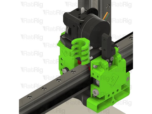
EVA3 cable_guide Printed Part
-
M3x12 Cap Head Screw
-
Fasten the two M3x12 screws through the EVA3 cable_guide and into the EVA3 cable_guide_mount
-
-
-
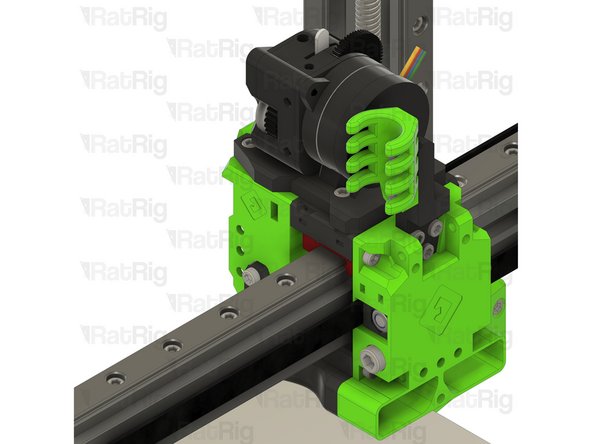
Phaetus Rapido UHF hot end assembly from Step 13
-
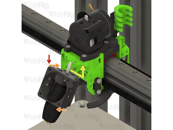
Angle the hot end assembly as shown
-
Guide the PTFE tube into hole in the top of the EVA3 universal front
-
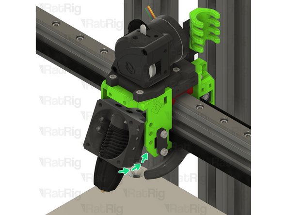
Rotate the hot end assembly into position as shown
-
Check that the assembly is aligned correctly. The M3 hex nuts should be visible through the marked holes
-
-
-
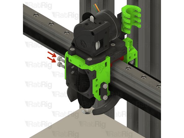
M3x8 Cap Head Screw
-
Fasten the four M3x8 screws through the EVA3 universal front and into the hot end assembly to secure it in place
-
Take care not to over tighten the M3 screws as you can damage the printed parts
-
-
-
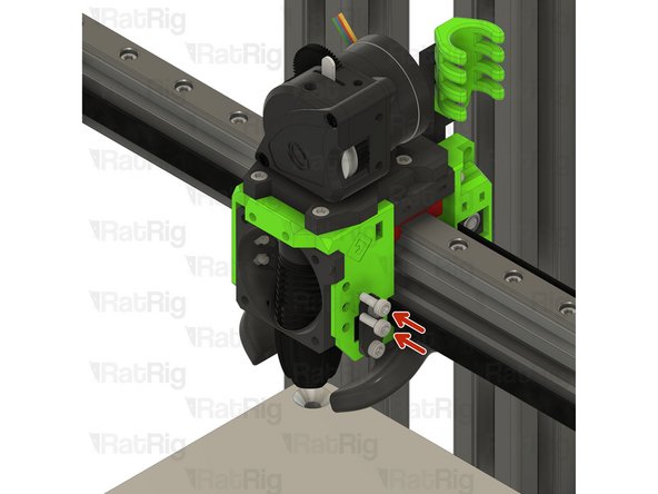
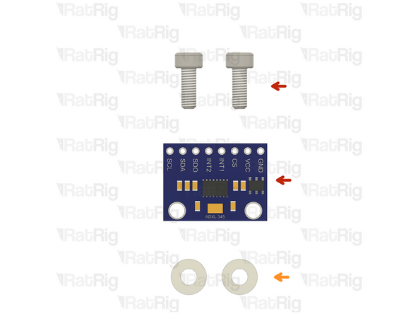
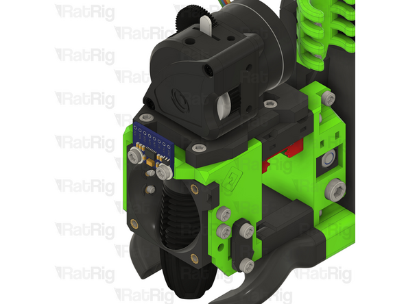
The ADXL module won't appear in the rest of the guide, as it only started being offered in V-Core 3.1 kits since October 2023
-
ADXL accelerometer module
-
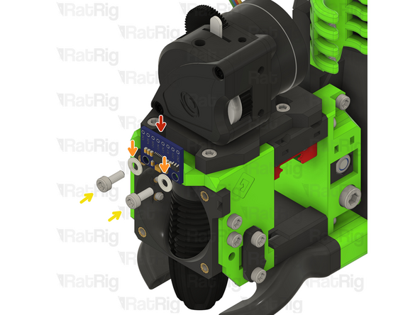
Align the ADXL module with the two holes in the EVA assembly
-
2x M3 nylon washers
-
The nylon washers are required to prevent damaging the sensitive electronics on the ADXL board
-
2x M3x8 Cap Head Screw
-
Tighten the M3x8 screws to secure the ADXL in place
-
Do not overtighten the screws as the ADXL will be permanently damaged
-
-
-
M3x20 Cap Head Screw
-
ratrig_eva3_shroud Printed Part
-
40x10mm 24V Axial Fan
-
Insert the M3x20 screws into the ratrig_eva3_shroud, through the 40mm fan and fasten them into the EVA3 front
Here's an article about which side of the fan is the intake side: https://www.pcworld.com/article/394576/h...
Money quote from it: "If the fan blades look rounded—that is, they’re curving away from you—that’s the intake side. (For the more technical out there: The convex side of the fan blades is the intake side.)
"If the fan blades look like the inside of a dish or bowl—that is, they’re curving toward you—that’s the exhaust side. (In other words, the concave side is where air exhausts.) Oftentimes, the exhaust side also has the crosshatch supports for the fan’s frame, with a circular sticker in the center that lists brand and model information."
generally, Fan cable should be up to the right ( from machine front) so that it points in direction of cable guide
Donald Fast - Resolved on Release Reply
Fan should be blowing onto the hot end. If you are lucky your fan will have an arrow showing airflow direction ( usually black print on edge of fan. If not guess with label out — if it is wrong, you can reverse the fan mount later
Donald Fast - Resolved on Release Reply
-
-
-
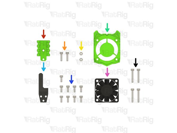
3x M3x8 Cap Head Screw
-
1x M3 Nylon Locking Hex Nut
-
1x EVA3 lj8_probe_mount Printed Part
-
1x Rat Rig SuperPinda Probe by P&F
-
-
-
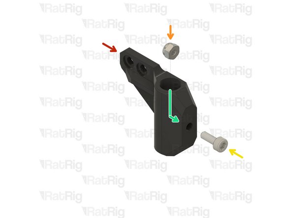
EVA3 lj8_probe_mount Printed Part
-
M3 Nylon Locking Hex Nut
-
M3x8 Cap Head Screw
-
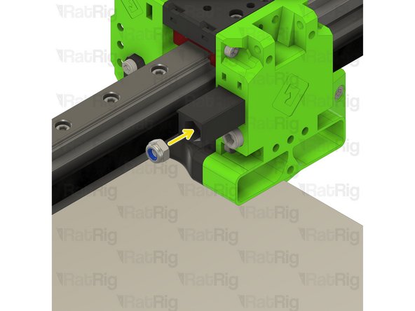
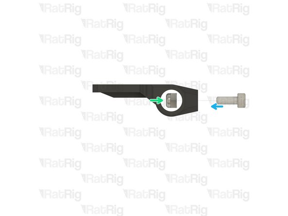
The M3 nylon locking hex nut must be installed inside the lj8_probe_mount printed part
-
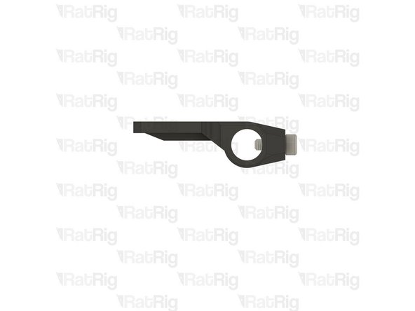
Fasten the M3x8 screw to pull the M3 nylon locking nut into position
I found the easiest way to do this is to hold the nut in place with a small magnet and then fastening the screw a few turns, so you can pull it in it's place.
Roodkpvoske - Resolved on Release Reply
-
-
-
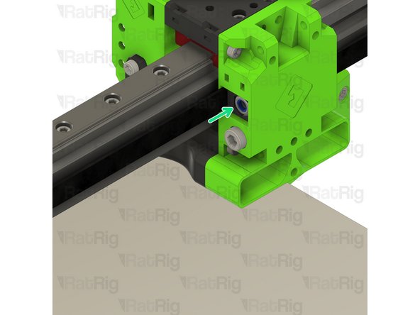
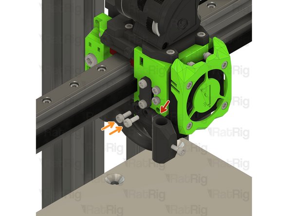
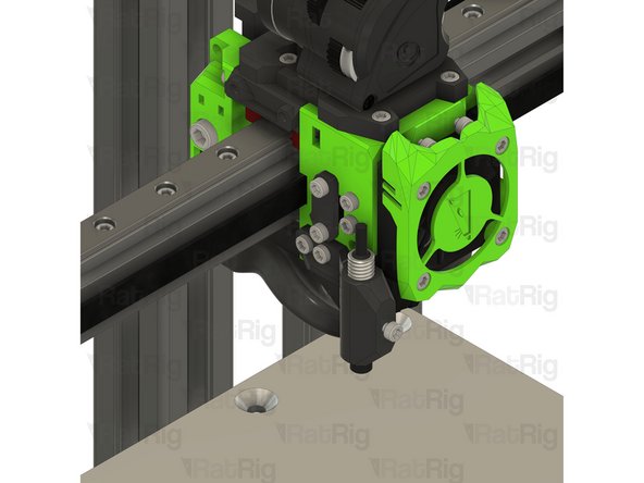
EVA3 lj8_probe_mount assembly from the previous step
-
Position the probe mount assembly as shown
-
M3x8 Cap Head Screw
-
Fasten the two M3x8 screws through the probe mount and into the EVA3 assembly
-
Rat Rig SuperPinda Probe by P&F
-
Insert the probe into the probe mount as shown
Before attaching the PINDA probe, one should add the DuPont connector according to Step 42 here: 14. Wiring, Firmware & RatOS
-
-
-
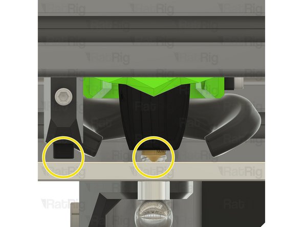
The Rat Rig SuperPinda Probe needs to be at the correct height to trigger properly
-
A recommended method to set the correct height is to rest the hot end nozzle on the bed, and then place a cable tie between the bed and the tip of the probe
-
Adjust the probe up to down as necessary to position the tip 1mm higher than the hot end nozzle
-
Tighten the M3x8 to secure the probe in place
-
Do not over-tighten the M3x8 screw, doing so can damage the probe or printed probe mount
-
Correct probe vs nozzle position
-
-
-
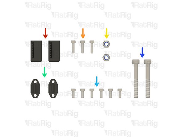
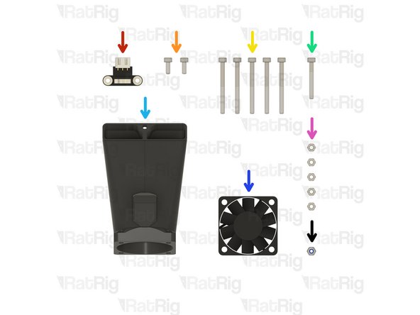
1x Endstop Module
-
2x M3x8 Cap Head Screw
-
5x M3x35 Cap Head Screw
-
1x M3x25 Cap Head Screw
-
1x EVA3 40mm_fan_inlet Printed Part
-
1x 4028 Part Cooling Fan
-
5x Hex Nut - M3
-
1x M3 Nylon Locking Hex Nut
-
-
-
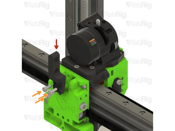
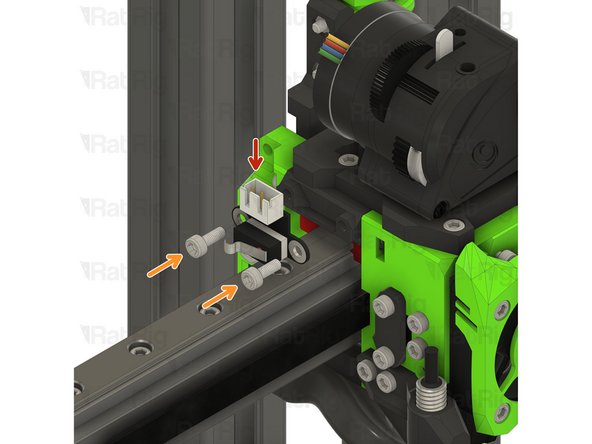
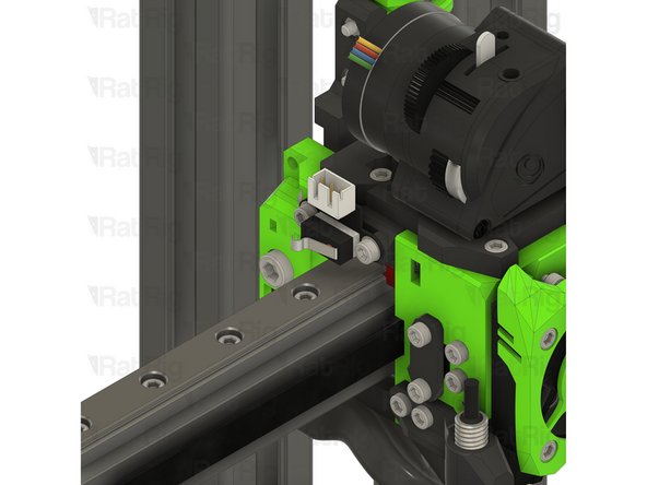
Endstop Module
-
M3x8 Cap Head Screw
-
Fasten the endstop module to the EVA3 assembly, as shown, using the M3x8 screws
-
These M3 screws fasten directly into the printed part. Take care not to over tighten them
-
-
-
EVA3 40mm_fan_inlet Printed Part
-
Hex Nut - M3
-
Insert an M3 hex nut into the 40mm_fan_inlet as shown
-
Fully install the M3 hex nut up and into the 40mm_fan_duct as shown
-
Repeat the process for the other three M3 hex nuts
-
-
-
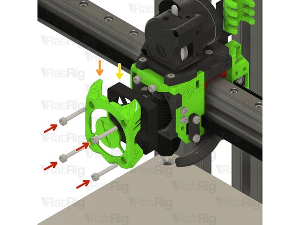
EVA3 40mm_fan_inlet assembly from the previous step
-
4028 Part Cooling Fan
-
M3x35 Cap Head Screw
-
Fasten the four M3x35 screws through the 4028 cooling fan and into the hex nuts within the 40mm_fan_inlet
-
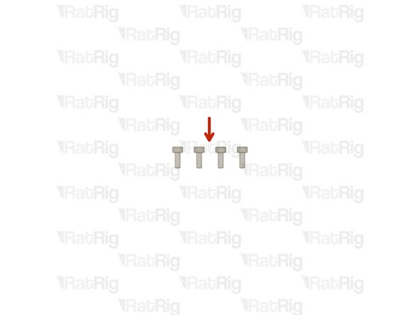
M3x35 Cap Head Screw
-
This M3x35 screw will be used in the next step to secure the 40mm_fan_inlet to the EVA3 assembly
Before attaching the 4028 cooling fan, one may wish to modify the fan to add the appropriate length wire leads and connectors, following Step 32 here: 14. Wiring, Firmware & RatOS
-
-
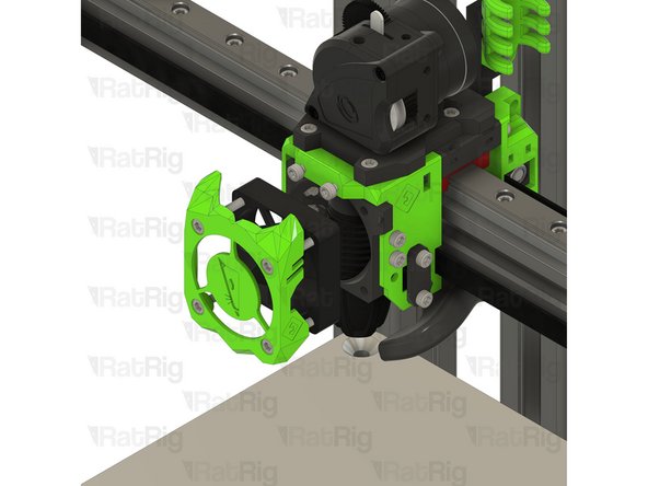
-
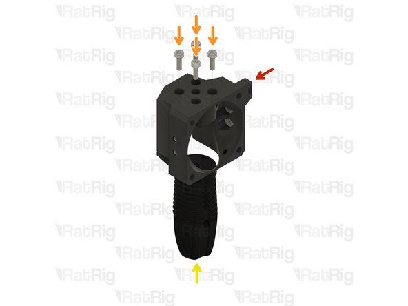
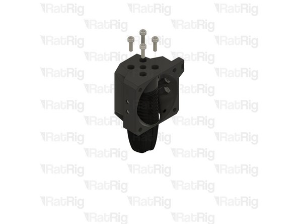
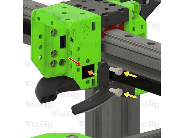
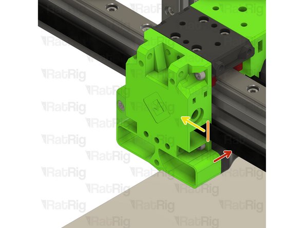
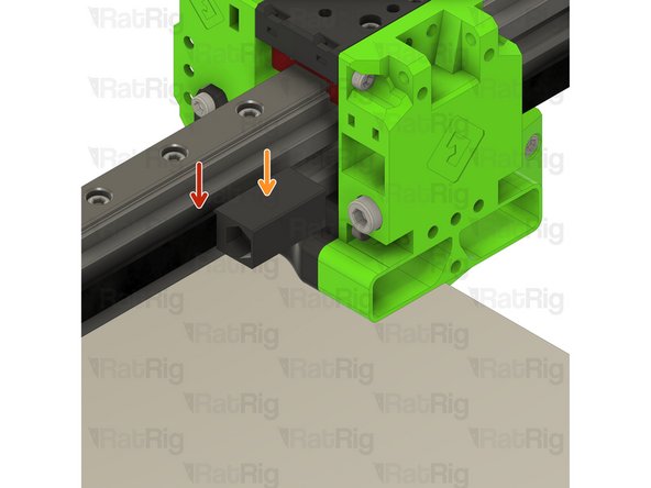
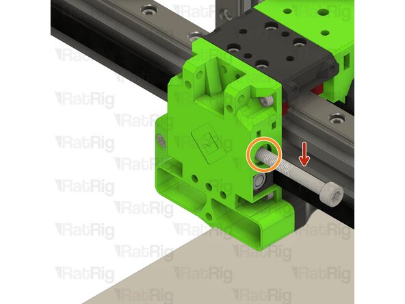
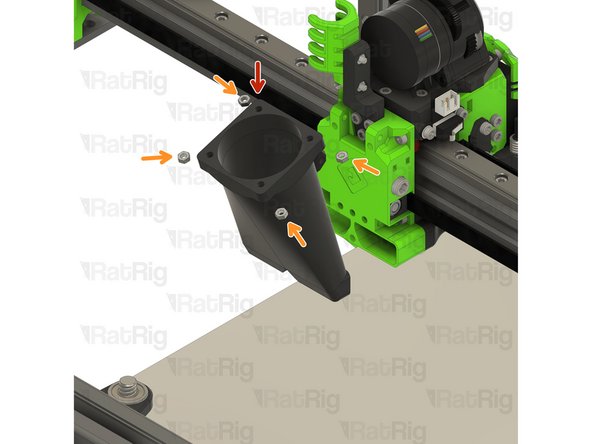
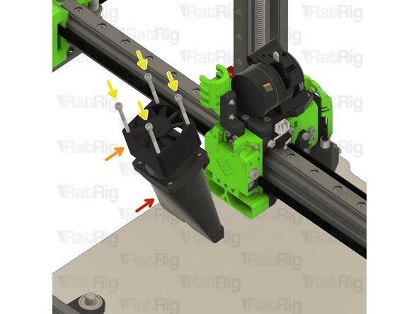
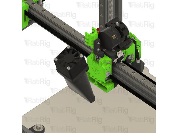
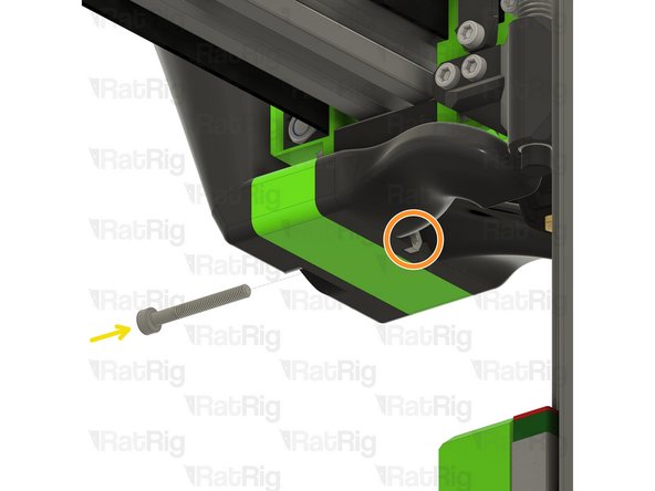
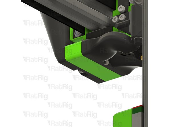
Install the 40mm_fan_duct assembly as shown
-
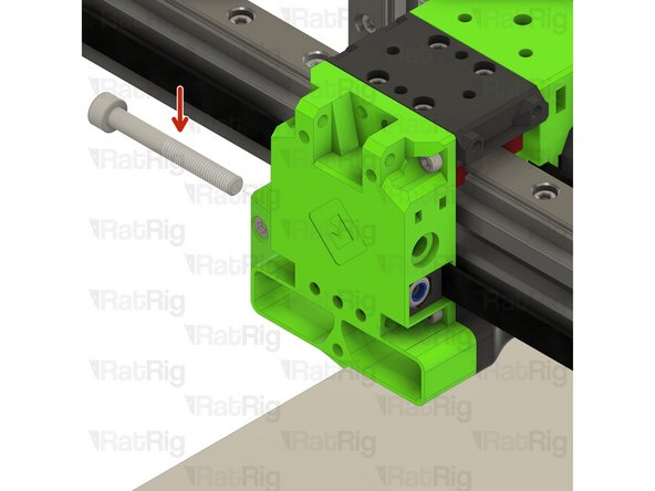
Push the M3x35 screw though the EVA3 assembly and 40mm_fan_duct as shown
-
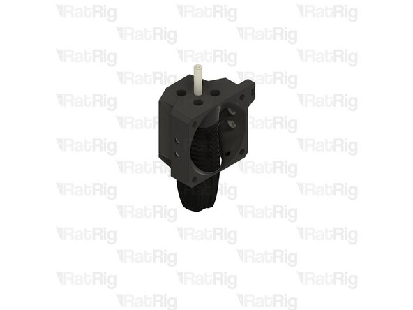
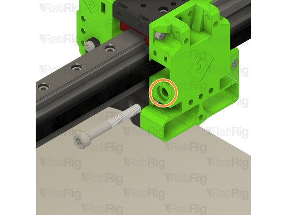
The tip of the M3x35 screw should extend out of the EVA3 assembly as shown
-
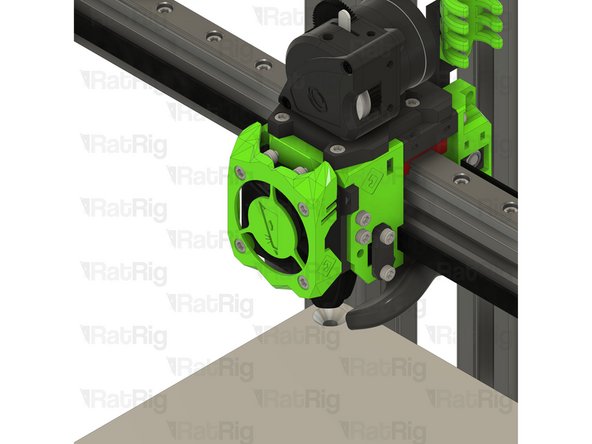
M3 Nylon Locking Hex Nut
-
Fasten the M3 nylon hex nut onto the M3x35 screw
-
-
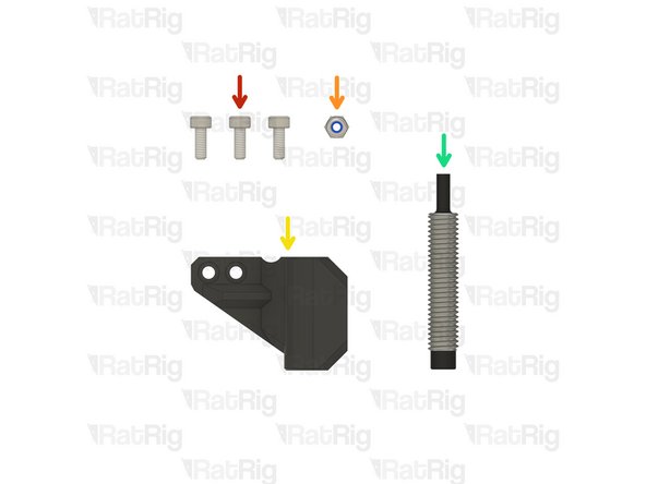
-
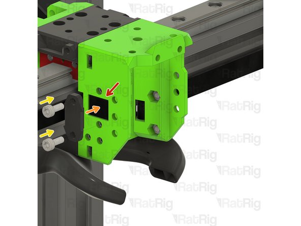
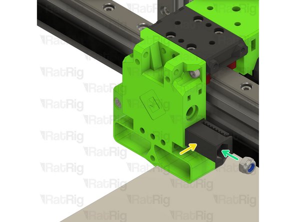
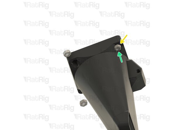
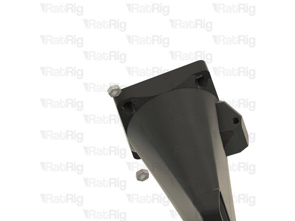
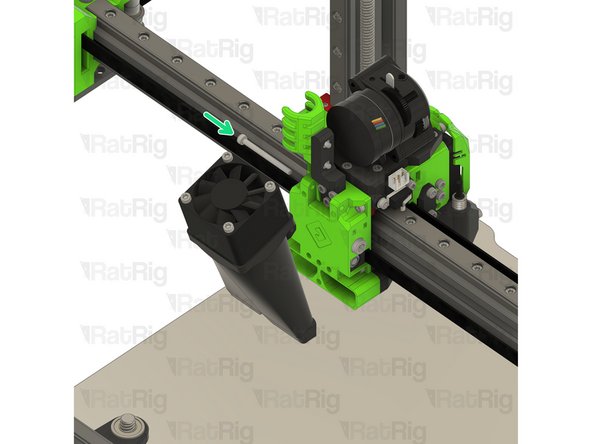
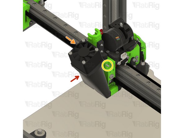
Hex Nut - M3
-
Position the M3 hex nut as shown
-
M3x25 Cap Head Screw
-
Fasten the M3x25 screw through the 40mm_fan_duct and into the M3 hex nut
-
Take care not to over tighten the M3 screw as you can damage the printed parts
-
-
-
Continue with the next guide:11. X-Axis Gantry Alignment
This guide has a TON of errors, and the step order does not work. 1) the block that attached to the linear rail mount must be completed immediately after assembly of the part, and 2) the parts need to immediately be mounted on the printer instead of being set aside. If you set the parts aside and mount them in the order stated, you won't be able to mount anything.
Also, I am using an LGX with a Mosquito Magnum, and this does not work for anything but the LGX Lite w/ Rapido. It will take several hours going back and forth between this manual and the EVA documents in order to get this working. Many of the screws called out are the wrong size as well, so you might need to find other parts. The screws called out to attach the shroud are like 5mm to short.
William Bosacker - Resolved on Release Reply
-


Cancel: I did not complete this guide.
10 other people completed this guide.
My extruder came with flat square nuts already installed, they didn't come with the kit
Nick D - Resolved on Release Reply