Introduction
Please note: All measurements provided in this guide are based on building a 300x300 V-Core 4.0.
If you are building a machine of a different size, the following adjustments can be made to the stated extrusion and linear rail lengths:
- 400x400: Add 100mm
- 500x500: Add 200mm
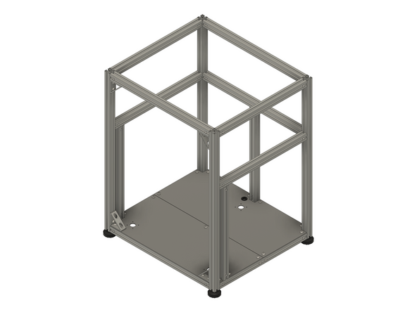
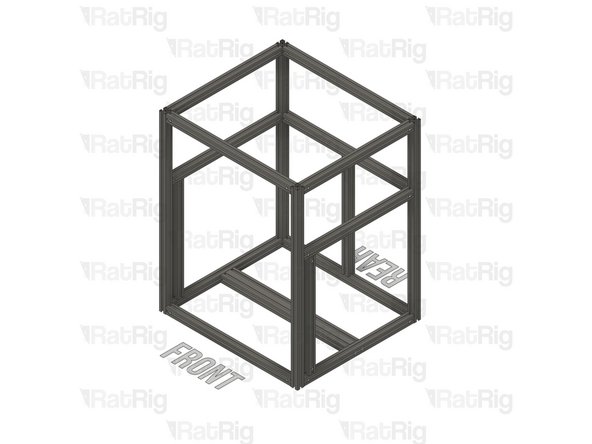
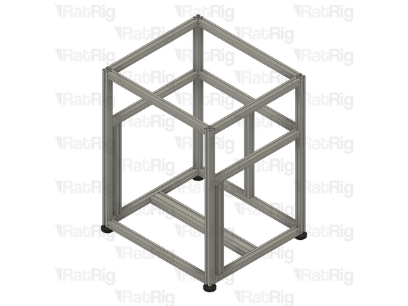
It is strongly recommended to assemble the frame on a known flat surface (such as a solid table, work surface or similar). Assembling the frame on a carpeted floor, tile floor or other non-flat surface can cause the finished frame to not be square. This can cause issues with print quality and performance.
-
-
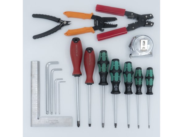
The following tools are required for this section of the guide:
-
Allen key / hex wrenches in the following sizes: 4mm & 5mm
-
Avoid using ball end hex wrenches on the Quick Connectors as they are more prone to damaging the heads of the Set Screws
-
Spanners / wrenches in the following size: 13mm
-
A pair of scissors
-
The following tools are recommended for this guide:
-
A tape measure
-
An Engineer Square
-
-
-
The following steps show how the aluminium extrusion Quick Connectors are prepared and installed. The V-Core 4.0 frame assembly begins on step 7
-
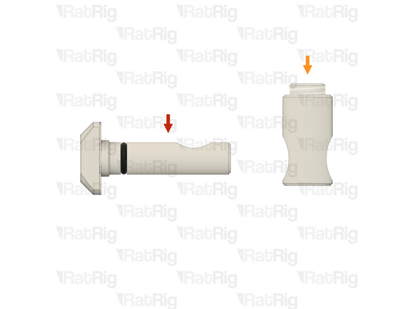
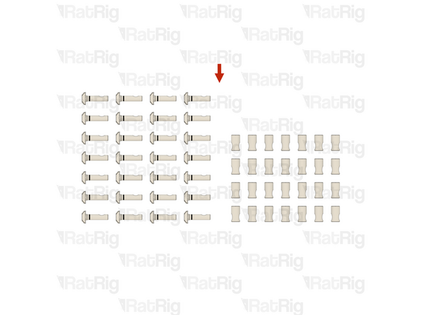
The Quick Connectors are supplied in two parts:
-
Quick Connector T-Nut Pin with the O-Ring pre-installed
-
Quick Connector Housing with the Set Screw pre-installed
-
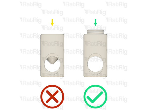
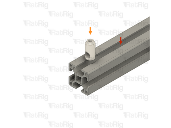
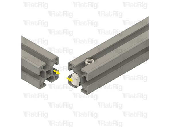
Before trying to install a Quick Connector Housing into an extrusion, check that the Set Screw is not blocking the hole in the Quick Connector Housing
-
If the Set Screw is blocking the hole in the Quick Connector Housing, slightly unscrew it to achieve the necessary clearance
-
-
-
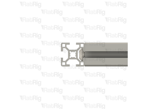
Example extrusion
-
Quick Connector Housing
-
Insert the Quick Connector Housing into the hole in the aluminium extrusion
-
Please note: If the Quick Connector Housing is difficult to insert into the aluminium extrusion, try inserting it from the opposite side
-
Make sure that the Quick Connector Housings all face the same direction
-
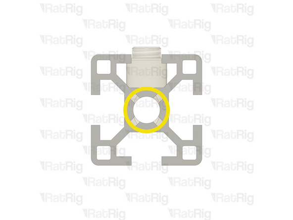
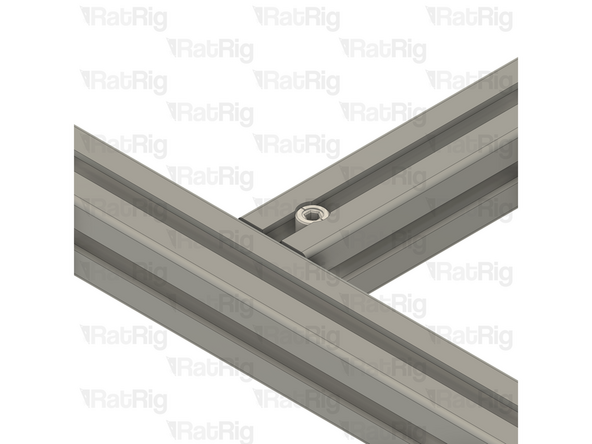
Make sure that the hole in the Quick Connector Housing is aligned with the central hole on the aluminium extrusion as shown
-
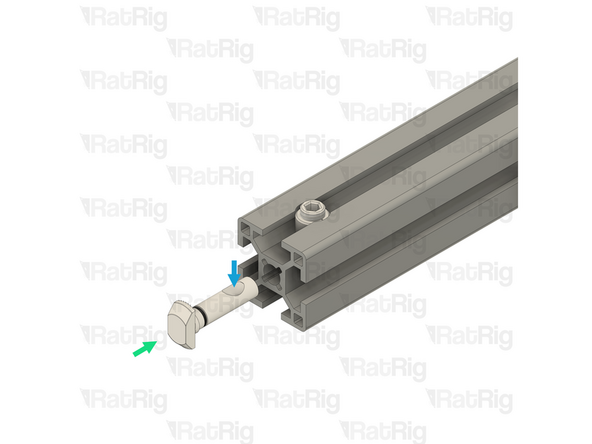
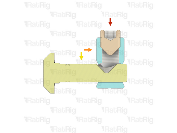
Insert the Quick Connector T-Nut Pin into the central hole on the extrusion slot
-
Make sure the "notch" in the pin is facing towards the Set Screw
-
-
-
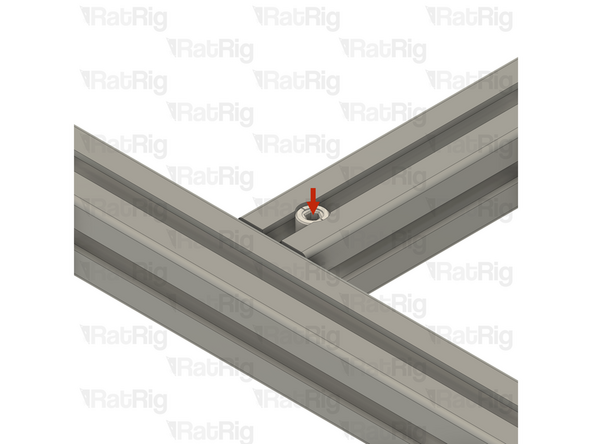
Quick Connector Set Screw
-
Using a 4mm hex key, tighten the Set Screw just enough to hold the Quick Connector T-Nut Pin inside the extrusion
-
If correctly tightened, the Quick Connector T-Nut Pin should still move slightly backwards and forwards, but should not come loose
-
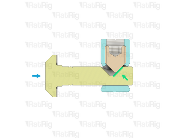
Slide the second aluminium extrusion into position, aligning the Quick Connector T-Nut Pin into the slot of the second aluminium extrusion
-
Be careful not to scratch the aluminium extrusions when assembling them
-
-
-
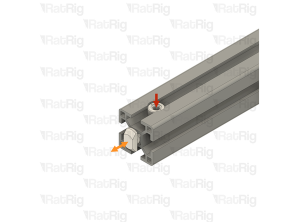
Quick Connector Housing Set Screw
-
Fully tighten the Set Screw to secure the extrusions together
-
The Set Screw will cause the Quick Connector T-Nut Pin to pull tight against the second extrusion, securing them together
-
If the extrusion connection is loose after fully tightening the Set Screw, loosen the Set Screw and check that the Quick Connector T-Nut Pin was properly positioned. The connection will not tighten if the "notch" on the pin is not aligned with the Set Screw
-
-
-
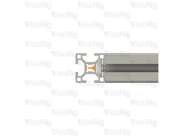
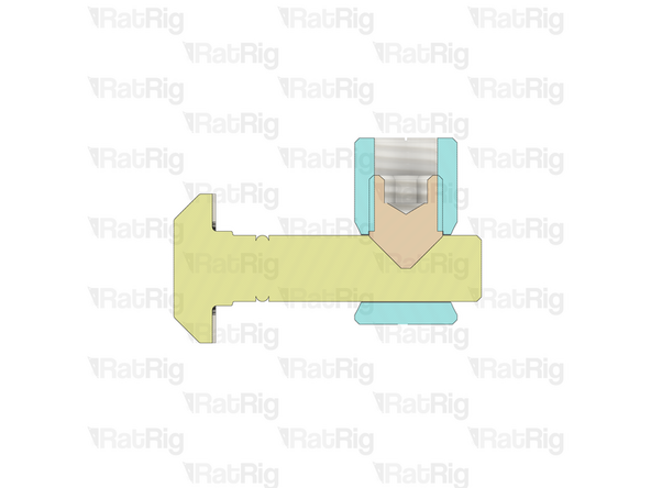
Set Screw
-
Quick Connector Housing
-
Quick Connector T-Nut Pin
-
The Set Screw within the Quick Connector Housing engages with the "notch" in the Quick Connector T-Nut Pin
-
As the Set Screw is fastened, the T-Nut Pin is pulled inwards, causing the extrusions to lock together
-
-
-
As mentioned in the introduction, all extrusion measurements in this guide are based on a V-Core 4.0 in the 300 size
-
If you are building a machine of a different size, the stated extrusion lengths can be adjusted as follows:
-
V-Core 4.0 - 400: Add 100mm to all measurements
-
V-Core 4.0 - 500: Add 200mm to all measurements
-
If a measurement requires a different adjustment—or none at all—it will be noted when relevant
-
-
-
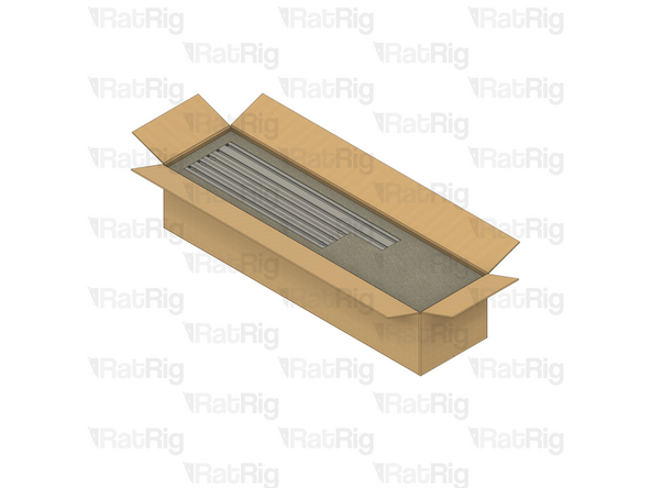
All of the extrusions for the V-Core 4.0 are provided packed in the same box. The SKU varies depending on the size being assembled:
-
V-Core 4.0 - 300: Rat Rig V-Core 4.0 - CNC Milled Profile Pack v1.0 - 300 (SKU: HW3984MK)
-
V-Core 4.0 - 400: Rat Rig V-Core 4.0 - CNC Milled Profile Pack v1.0 - 400 (SKU: HW3985MK)
-
V-Core 4.0 - 500: Rat Rig V-Core 4.0 - CNC Milled Profile Pack v1.0 - 500 (SKU: HW3986MK)
-
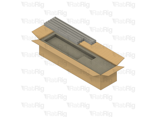
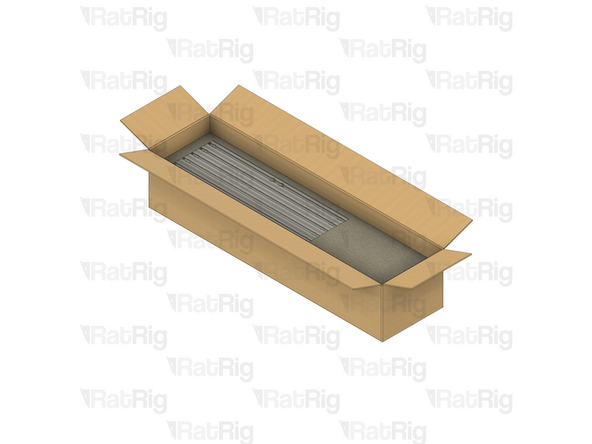
Be careful when opening the package. Do not use a long blade to cut the box open as you can damage the extrusions
-
Unpack each layer carefully, placing the extrusions to the side for now
-
There are four layers of extrusions to unpack
-
The 2020 V-Slot extrusion will be used in a later guide. All others are used in the construction of the frame
-
-
-
If you are building a machine of a different size, add 100mm to all listed extrusion lengths for the V-Core 4.0 400 or 200mm for the V-Core 4.0 500
-
28x Quick Connector for 30 series B-Type - 0º (SKU: HW3347GC)
-
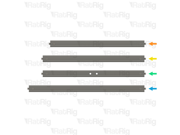
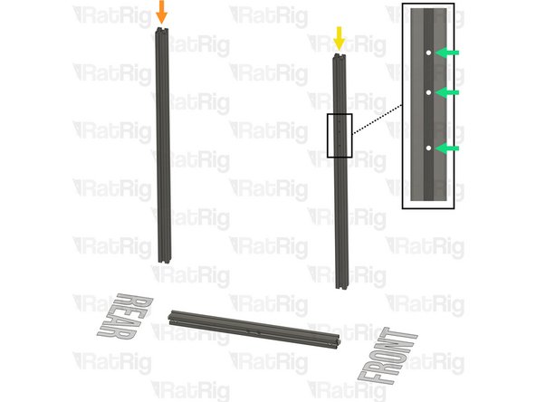
Install Quick Connectors into both ends of the following extrusions:
-
3x T-Slot 3030 Milled Extrusion - 440mm
-
4x T-Slot 3030 Milled Extrusion - 475mm
-
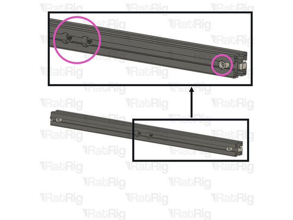
2x T-Slot 3030 Milled Extrusion - 475mm with two M8 holes
-
Make sure the Quick Connector Set Screws are facing the same side as the counterbores for the M8 screw holes
-
5x T-Slot 3030 Milled Extrusion - 540mm
-
-
-
If you are building a machine of a different size, add 100mm to all listed extrusion lengths for the V-Core 4.0 400 or 200mm for the V-Core 4.0 500
-
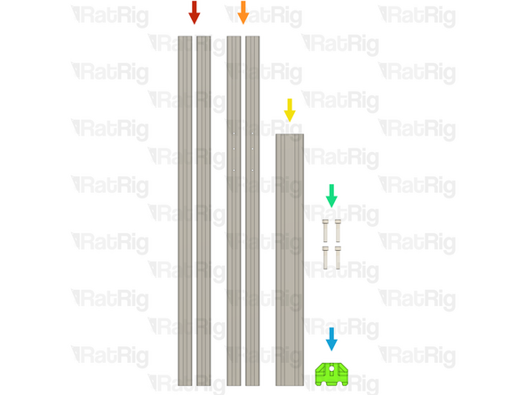
In addition to the extrusions prepared in the previous step, the following extrusions are needed to assemble the frame:
-
2x T-Slot 3030 Milled Extrusion - 750mm
-
2x T-Slot 3030 Milled Extrusion - 750mm with three M4 holes
-
1x T-Slot 3060 Milled Extrusion - 540mm
-
4x M8x40 Cap Head Screw (SKU: HW1871SC)
-
1x vc4_frame_jig Printed Part (SKU: PP000279)
-
Please note: The Frame Jig may have been printed in green or black. The design is the same regardless of colour
-
-
-
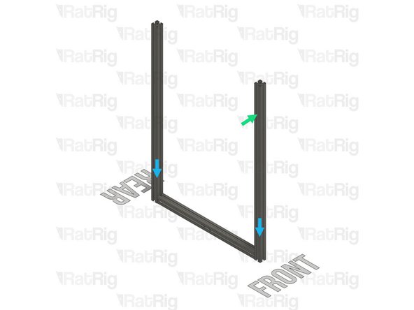
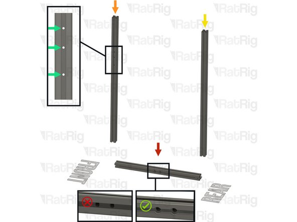
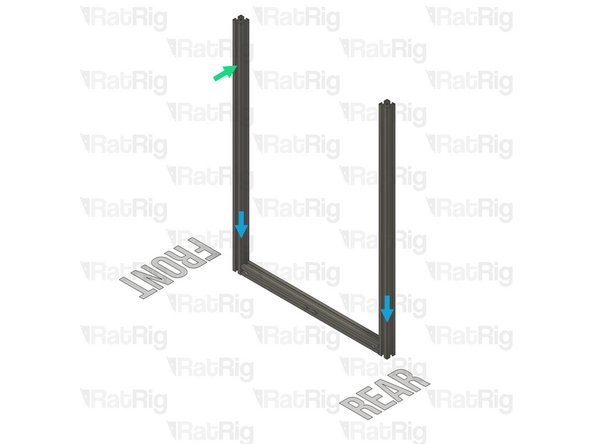
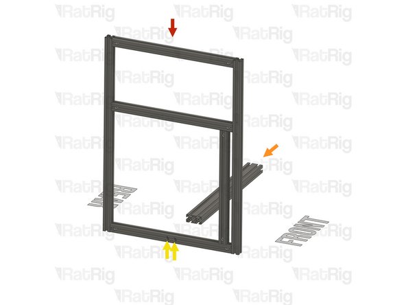
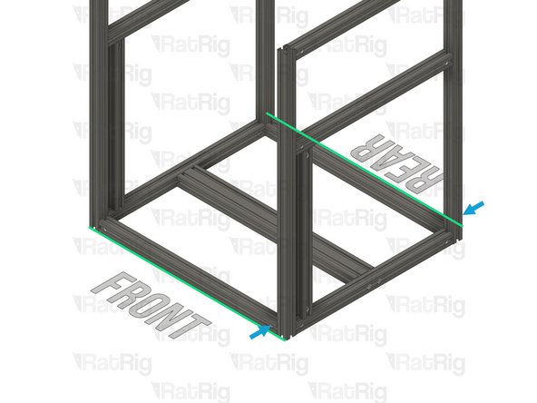
T-Slot 3030 Milled Extrusion - 475mm with Quick Connectors and two M8 holes from step 9
-
Make sure that the counterbores for the M8 holes are oriented as shown
-
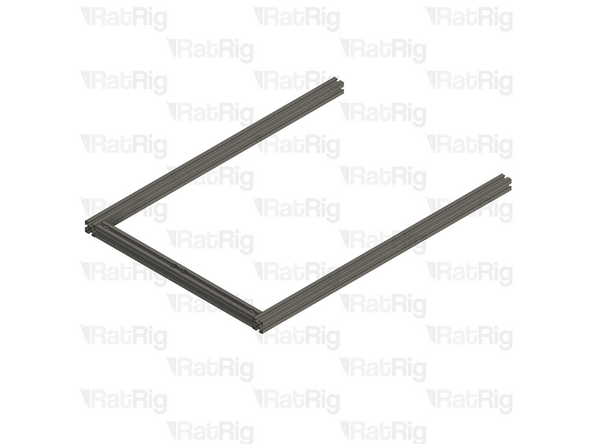
T-Slot 3030 Milled Extrusion - 750mm
-
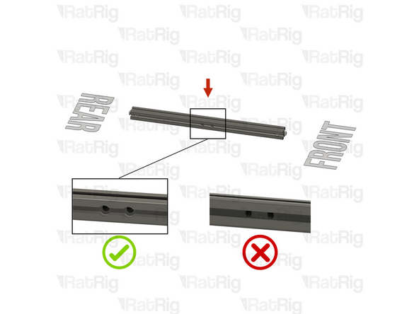
T-Slot 3030 Milled Extrusion - 750mm with three M4 holes
-
Make sure this extrusion is installed as shown. It should be at the front, with the three M4 holes at the top and facing to the side
-
Assemble the extrusions as shown but do not fasten them together yet
-
Be careful not to scratch the aluminium extrusions when assembling them
-
-
-
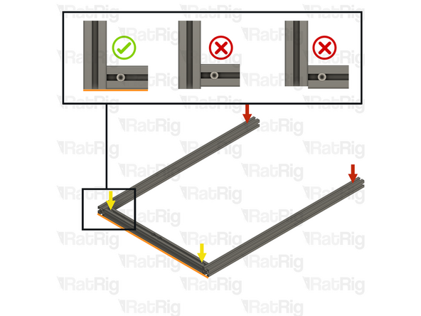
Lay the assembly on a flat surface, this is crucial to ensure a square frame
-
Good surfaces: Poured self-levelled concrete, glass, or a stone countertop
-
Bad surfaces: Carpeted floor, a tile floor, or rough concrete
-
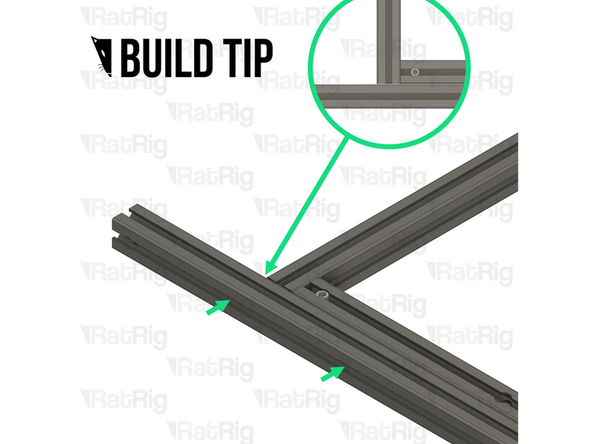
Align the extrusions as shown - making sure the ends are flush
-
Build Tip: You can use a spare 3030 extrusion or an Engineer Square to help align the assembly
-
Fasten the Set Screws in both of the Quick Connectors to secure the extrusions together
-
If the extrusion connection is loose after fully tightening the Set Screw, loosen the Set Screw and check that the Quick Connector T-Nut Pin was properly positioned. The connection will not tighten if the "notch" on the pin is not aligned with the Set Screw
-
-
-
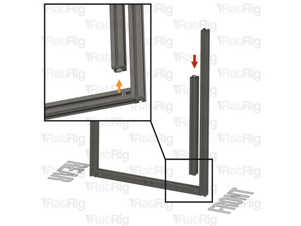
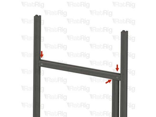
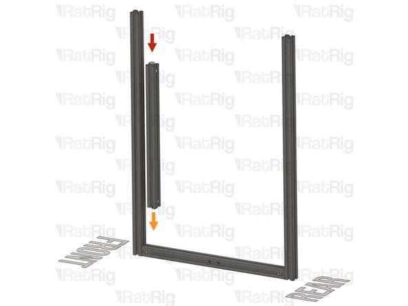
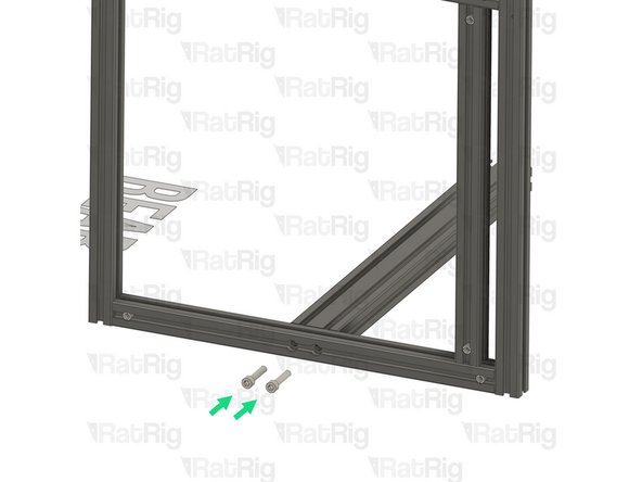
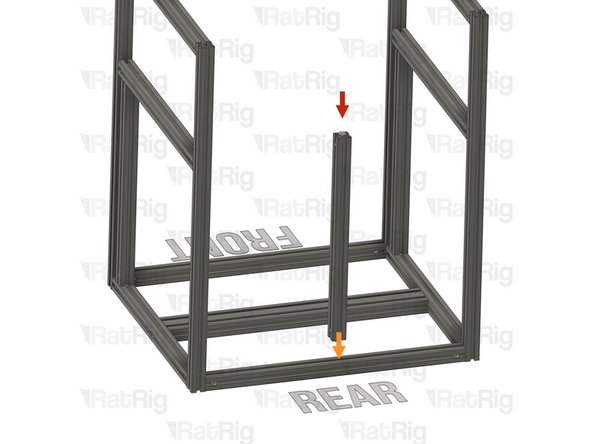
T-Slot 3030 Milled Extrusion - 440mm with Quick Connectors from step 9
-
Align the Quick Connector T-Nut Pin with the bottom extrusion slot
-
Insert the Quick Connector T-Nut Pin into the bottom extrusion slot
-
T-Slot 3030 Milled Extrusion - 475mm with Quick Connectors from step 9
-
Insert the extrusion into the side assemblies, making sure the Quick Connector T-Nut Pins are aligned with the side extrusion slots
-
Be careful not to scratch the aluminium extrusions when assembling them
-
-
-
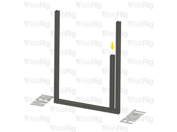
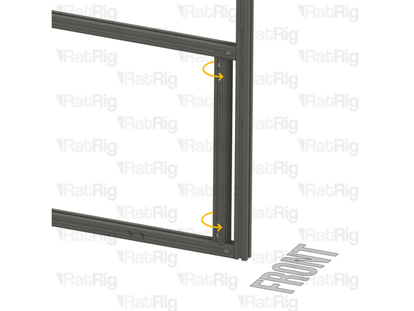
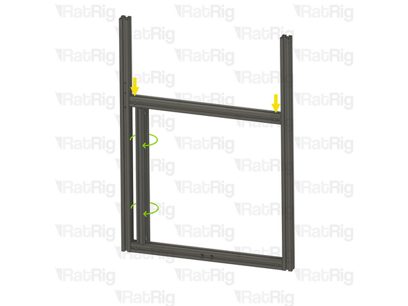
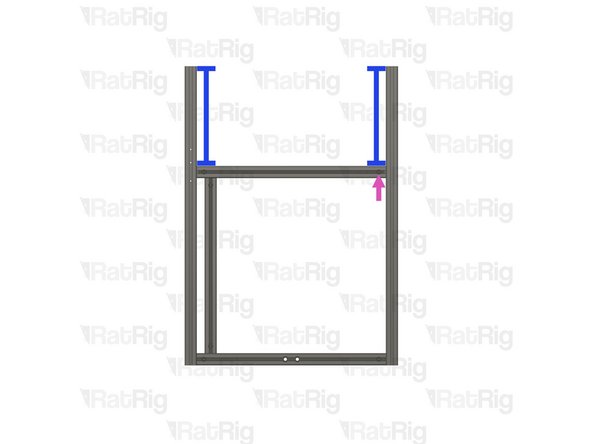
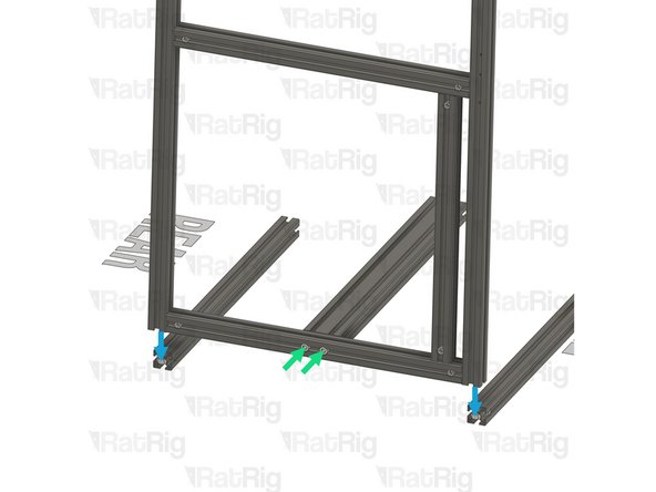
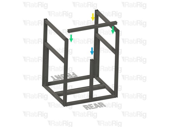
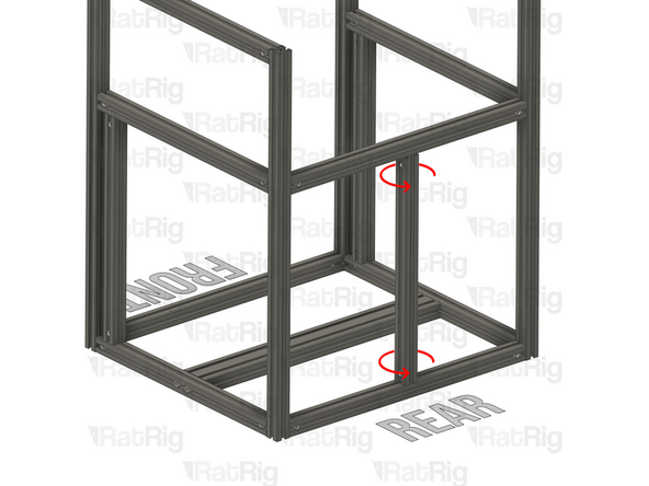
Slide the marked extrusion downwards, making sure the Quick Connector T-Nut Pin on the 440mm extrusion fits inside the extrusion slot
-
Carefully rotate the marked extrusion 90 degrees so that the Quick Connector Set Screws face outwards as shown
-
Look into the extrusion slots and make sure that both the upper and lower Quick Connector T-Nut Pins have rotated correctly
-
Be careful not to scratch the aluminium extrusions when assembling them
-
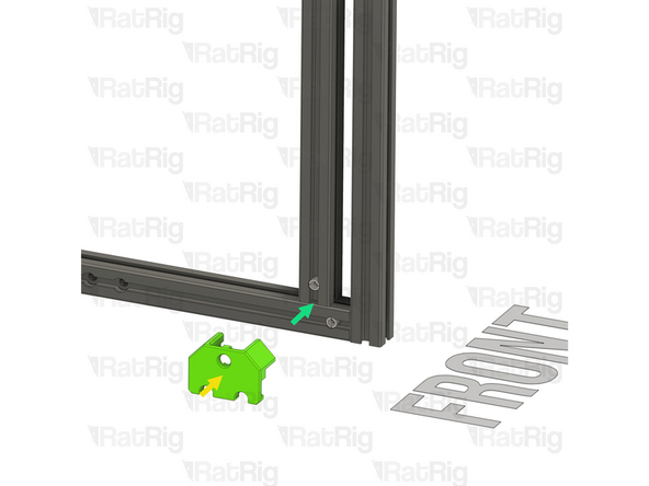
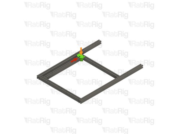
V-Core 4.0 Frame Jig
-
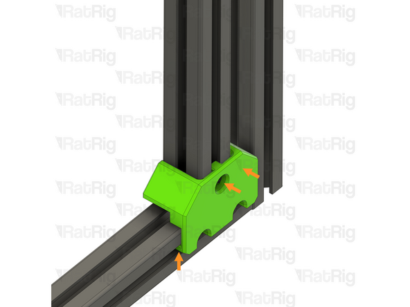
Install the Frame Jig onto the assembly as shown
-
-
-
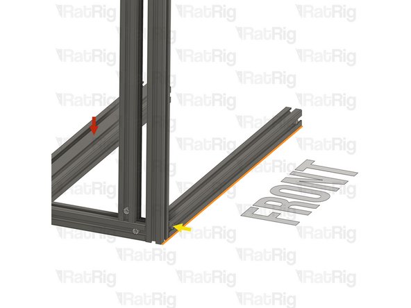
Lay the assembly on a flat surface, this is crucial to ensure a square frame
-
Make sure the Frame Jig is installed completely flush with the extrusion and that the bottom "tabs" are within the extrusion slot
-
Push the Frame Jig to the right to eliminate any space between the Frame Jig and the front extrusion
-
The marked gap should measure 20mm. This measurement is the same for all V-Core 4.0 sizes
-
Build Tip: You can use the 2020 V-Slot extrusion to verify the gap but be careful not to scratch the aluminium extrusions
-
Fully tighten the marked Set Screw to secure the extrusions together
-
If the extrusion connection is loose after fully tightening the Set Screw, loosen the Set Screw and check that the Quick Connector T-Nut Pin was properly positioned. The connection will not tighten if the "notch" on the pin is not aligned with the Set Screw
-
-
-
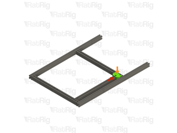
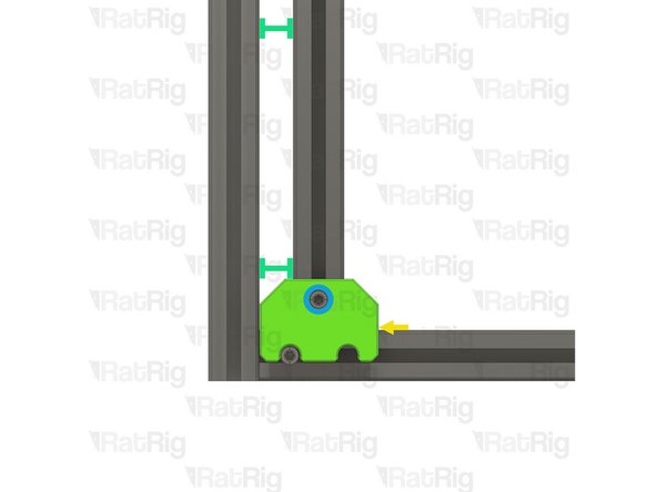
Move the Frame Jig to the marked position
-
Make sure the Frame Jig is installed completely flush with the extrusion and that the bottom "tabs" are within the extrusion slot
-
Push the Frame Jig to the right to eliminate any space between the Frame Jig and the front extrusion
-
The marked gap should measure 20mm. This measurement is the same for all V-Core 4.0 sizes
-
Fully tighten both of the marked Set Screws to secure the extrusions together
-
Double check that the marked distance is 250mm. This measurement is the same for all V-Core 4.0 sizes
-
Fully tighten the marked Set Screw to secure the extrusions together
-
If any of the extrusion connections are loose after fully tightening the Set Screws, loosen the Set Screw on the loose joint and check that the Quick Connector T-Nut Pin was properly positioned. The connection will not tighten if the "notch" on the pin is not aligned with the Set Screw
-
-
-
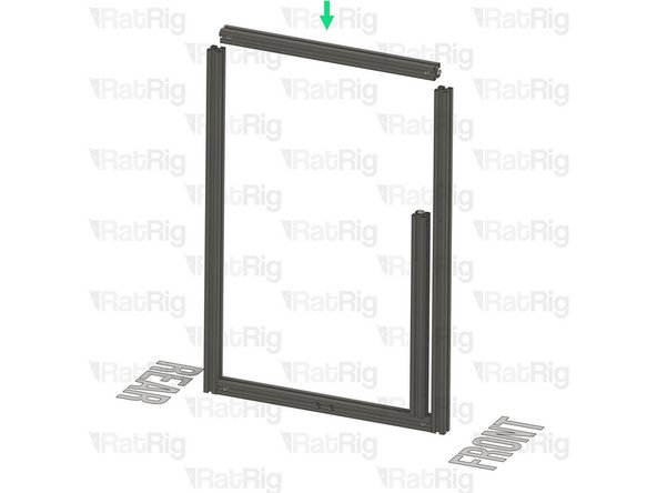
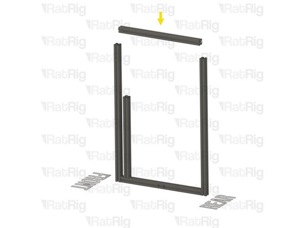
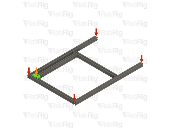
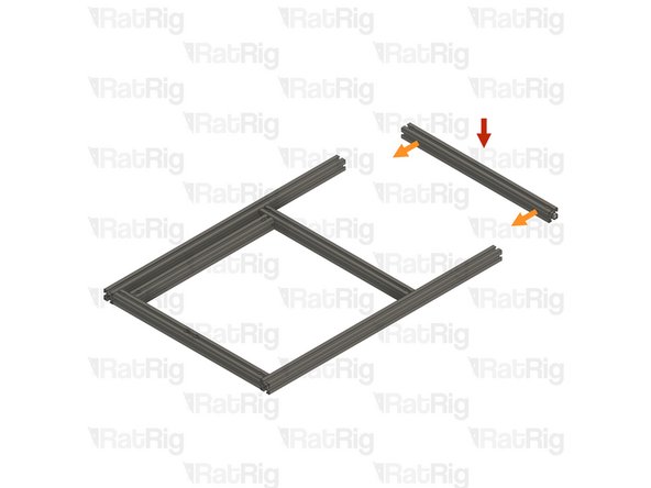
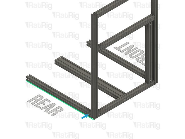
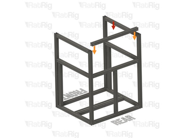
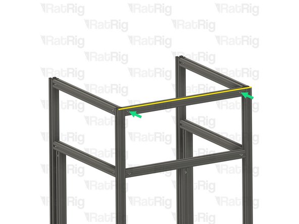
T-Slot 3030 Milled Extrusion - 475mm with Quick Connectors from step 9
-
Insert the extrusion into the side assemblies, making sure the Quick Connector T-Nut Pins are aligned with the side extrusion slots
-
Be careful not to scratch the aluminium extrusions when assembling them
-
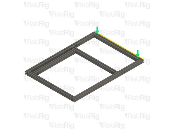
Align the extrusions as shown - making sure the ends are flush
-
Refer to step 12 for instructions on how to correctly align the extrusions
-
Fully tighten both of the marked Set Screws to secure the extrusions together
-
If any of the extrusion connections are loose after fully tightening the Set Screws, loosen the Set Screw on the loose joint and check that the Quick Connector T-Nut Pin was properly positioned. The connection will not tighten if the "notch" on the pin is not aligned with the Set Screw
-
Set this assembly aside until step 24
-
-
-
T-Slot 3030 Milled Extrusion - 475mm with Quick Connectors and two M8 holes from step 9
-
Make sure that the counterbores for the M8 holes are oriented as shown
-
T-Slot 3030 Milled Extrusion - 750mm with three M4 holes
-
T-Slot 3030 Milled Extrusion - 750mm
-
Make sure this extrusion is installed as shown. It should be at the front, with the three M4 holes at the top and facing to the side
-
Assemble the extrusions as shown but do not fasten them together yet
-
-
-
Lay the assembly on a flat surface, this is crucial to ensure a square frame
-
Good surfaces: Poured self-levelled concrete, glass, or a stone countertop
-
Bad surfaces: Carpeted floor, a tile floor, or rough concrete
-
Align the extrusions as shown - making sure the ends are flush
-
Build Tip: You can use a spare 3030 extrusion or an Engineer Square to help align the assembly
-
Fasten the Set Screws in both of the Quick Connectors to secure the extrusions together
-
If the extrusion connection is loose after fully tightening the Set Screw, loosen the Set Screw and check that the Quick Connector T-Nut Pin was properly positioned. The connection will not tighten if the "notch" on the pin is not aligned with the Set Screw
-
-
-
T-Slot 3030 Milled Extrusion - 440mm with Quick Connectors from step 9
-
Align the Quick Connector T-Nut Pin with the bottom extrusion slot and insert it
-
T-Slot 3030 Milled Extrusion - 475mm with Quick Connectors from step 9
-
Insert the extrusion into the side assemblies, making sure the Quick Connector T-Nut Pins are aligned with the side extrusion slots
-
Slide the extrusion downwards, making sure the Quick Connector T-Nut Pin on the 440mm extrusion fits inside the extrusion slot
-
Carefully rotate the marked extrusion 90 degrees so that the Quick Connector Set Screws face outwards as shown
-
Look into the extrusion slots and make sure that both the upper and lower Quick Connector T-Nut Pins have rotated correctly
-
Be careful not to scratch the aluminium extrusions when assembling them
-
-
-
Lay the assembly on a flat surface, this is crucial to ensure a square frame
-
Install the Frame Jig onto the assembly as shown
-
Make sure the Frame Jig is installed completely flush with the extrusion and that the bottom "tabs" are within the extrusion slot
-
Push the Frame Jig to the left to eliminate any space between the Frame Jig and the front extrusion
-
The marked gap should measure 20mm. This measurement is the same for all V-Core 4.0 sizes
-
Build Tip: You can use the 2020 V-Slot extrusion to verify the gap but be careful not to scratch the aluminium extrusions
-
Fully tighten the marked Set Screw to secure the extrusions together
-
If the extrusion connection is loose after fully tightening the Set Screw, loosen the Set Screw and check that the Quick Connector T-Nut Pin was properly positioned. The connection will not tighten if the "notch" on the pin is not aligned with the Set Screw
-
-
-
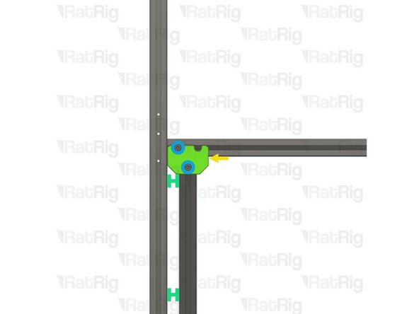
Move the Frame Jig to the marked position
-
Make sure the Frame Jig is installed completely flush with the extrusion and that the bottom "tabs" are within the extrusion slot
-
Push the Frame Jig to the left to eliminate any space between the Frame Jig and the front extrusion
-
The marked gap should measure 20mm. This measurement is the same for all V-Core 4.0 sizes
-
Fully tighten both of the marked Set Screws to secure the extrusions together
-
Double check that the marked distance is 250mm. This measurement is the same for all V-Core 4.0 sizes
-
Fully tighten the marked Set Screw to secure the extrusions together
-
If any of the extrusion connections are loose after fully tightening the Set Screws, loosen the Set Screw on the loose joint and check that the Quick Connector T-Nut Pin was properly positioned. The connection will not tighten if the "notch" on the pin is not aligned with the Set Screw
-
-
-
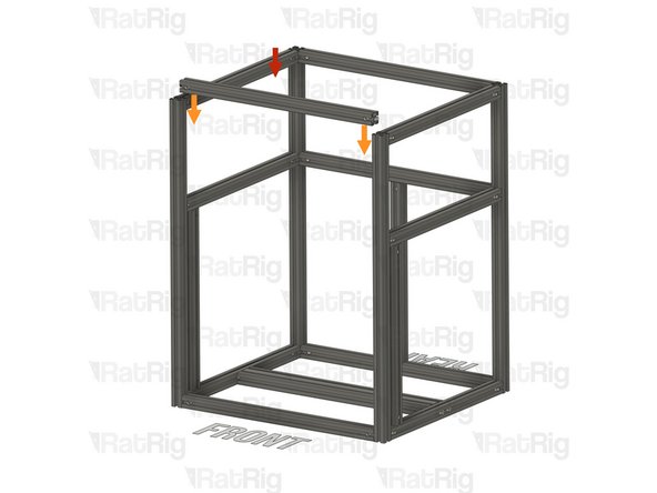
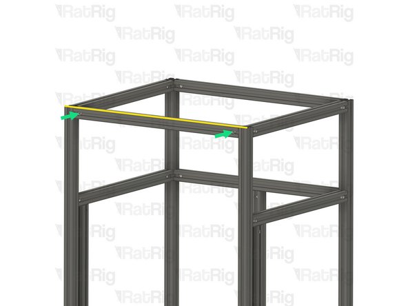
T-Slot 3030 Milled Extrusion - 475mm with Quick Connectors from step 9
-
Insert the extrusion into the side assemblies, making sure the Quick Connector T-Nut Pins are aligned with the side extrusion slots
-
Be careful not to scratch the aluminium extrusions when assembling them
-
Align the extrusions as shown - making sure the ends are flush
-
Refer to step 12 for instructions on how to correctly align the extrusions
-
Fully tighten both of the marked Set Screws to secure the extrusions together
-
If any of the extrusion connections are loose after fully tightening the Set Screws, loosen the Set Screw on the loose joint and check that the Quick Connector T-Nut Pin was properly positioned. The connection will not tighten if the "notch" on the pin is not aligned with the Set Screw
-
-
-
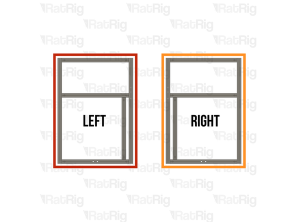
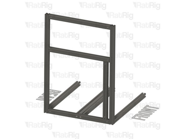
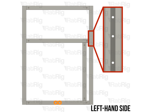
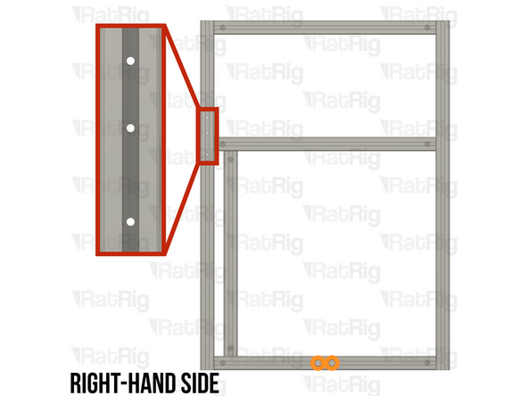
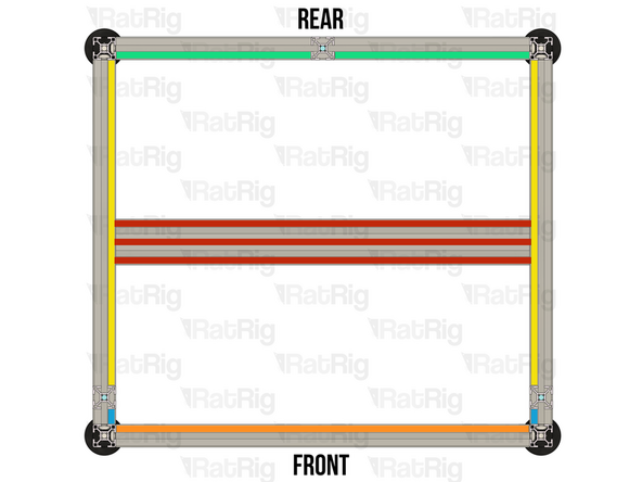
Make sure that the two frame side sub-assemblies match the provided image:
-
Left-hand side sub-assembly assembled in step 11 through to step 17
-
Right-hand side sub-assembly assembled in step 18 through step 23
-
The two sub-assemblies should be a mirror of each other
-
It is important to verify that the assemblies are correctly mirrored. Incorrect assembly will lead to significant issues during later steps
-
-
-
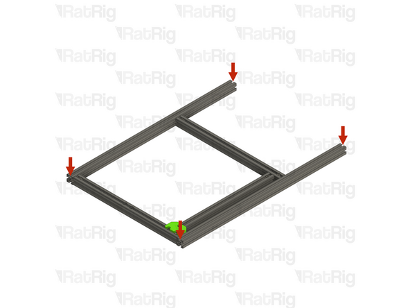
Left-hand side sub-assembly from step 17
-
T-Slot 3060 Milled Extrusion - 540mm from step 10
-
Align the holes in the 3060 extrusion with the M8 holes in the bottom extrusion of the left-hand side sub-assembly
-
2x M8x40 Cap Head Screw from step 10
-
Insert each M8x40 Cap Head Screw through the M8 holes in the bottom extrusion of the sub-assembly. Carefully begin to thread them into the end of the T-Slot 3060 extrusion before fully tightening them to secure the extrusions together
-
2x T-Slot 3030 Milled Extrusion - 540mm with Quick Connectors from step 9
-
Insert each extrusion into the side assembly. Make sure the Quick Connector T-Nut pins are aligned with the side extrusion slots and the Quick Connector Set Screws are facing outwards
-
Be careful not to scratch the aluminium extrusions when assembling them
-
-
-
Place the assembly on a flat surface, this is crucial to ensure the extrusions are aligned and the frame is square
-
Make sure that the front extrusion is flush with the side assembly
-
Fully tighten the marked Set Screw on the front to secure the extrusion to the sub-assembly
-
Make sure that the rear extrusion is flush with the side assembly
-
Fully tighten the marked Set Screw on the rear to secure the extrusion to the sub-assembly
-
If the extrusion connection is loose after fully tightening the Set Screw, loosen the Set Screw and check that the Quick Connector T-Nut Pin was properly positioned. The connection will not tighten if the "notch" on the pin is not aligned with the Set Screw
-
Make sure to support the frame assembly to ensure that it does not fall over
-
-
-
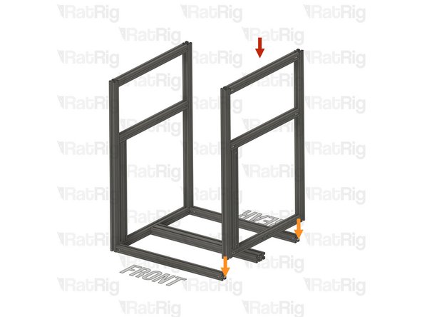
Right-hand side sub-assembly from step 23
-
Slide the right-hand side sub-assembly down onto the frame assembly. Make sure the Quick Connector T-Nut Pins are aligned with the side extrusion slots
-
Be careful not to scratch the aluminium extrusions when assembling them
-
2x M8x40 Cap Head Screw from step 10
-
Insert each M8x40 Cap Head Screw through the M8 holes in the bottom extrusion of the sub-assembly. Carefully begin to thread them into the end of the T-Slot 3060 extrusion before fully tightening them to secure the extrusions together
-
Make sure that the front and rear extrusions are flush with the side sub-assembly
-
Fully tighten the marked Set Screws on the front and rear to secure the side sub-assembly to the rest of the frame
-
If the extrusion connection is loose after fully tightening the Set Screw, loosen the Set Screw and check that the Quick Connector T-Nut Pin was properly positioned. The connection will not tighten if the "notch" on the pin is not aligned with the Set Screw
-
-
-
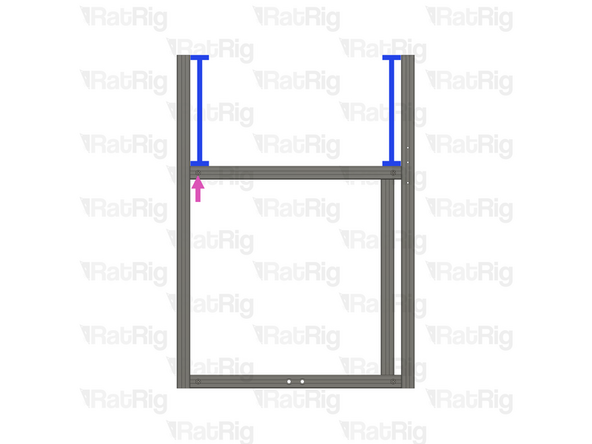
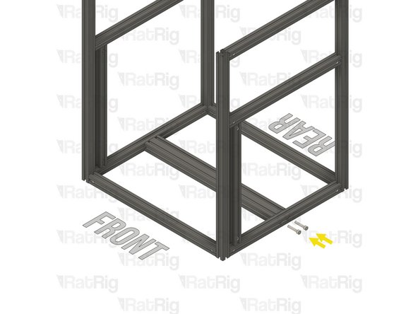
T-Slot 3030 Milled Extrusion - 440mm with Quick Connectors from step 9
-
Align the Quick Connector T-Nut Pin with the bottom extrusion slot and insert it
-
T-Slot 3030 Milled Extrusion - 540mm with Quick Connectors from step 9
-
Insert the extrusion into the side assemblies, making sure the Quick Connector T-Nut Pins are aligned with the side extrusion slots and the Quick Connector Set Screws are facing outwards
-
Slide the extrusion downwards, making sure the Quick Connector T-Nut Pin on the 440mm extrusion fits inside the extrusion slot
-
Be careful not to scratch the aluminium extrusions when assembling them
-
-
-
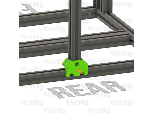
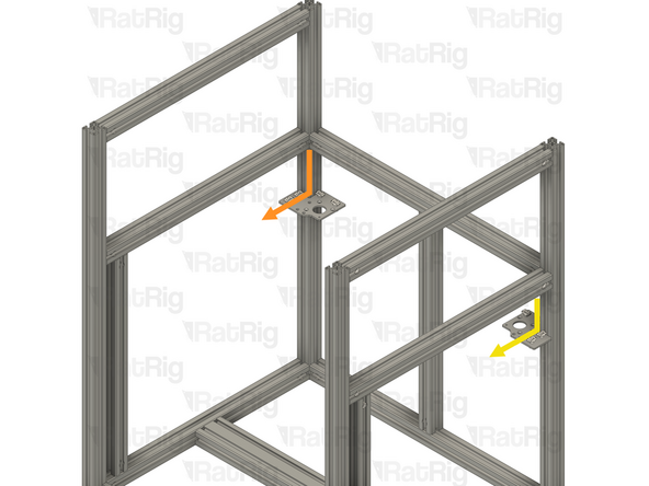
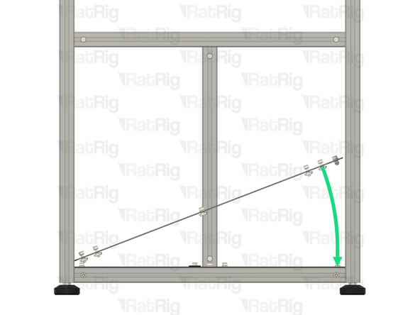
Carefully rotate the marked extrusion 90 degrees so that the Quick Connector Set Screws face towards the rear as shown
-
Look into the extrusion slots and make sure that both the upper and lower Quick Connector T-Nut Pins have rotated correctly
-
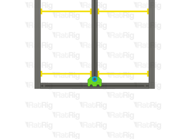
Install the Frame Jig onto the assembly as shown
-
Measure the marked gap on both sides, they should be equal and measure 255mm
-
V-Core 4.0 - 400: The gaps should measure 305mm
-
V-Core 4.0 - 500: The gaps should measure 355mm
-
Fully tighten the marked Set Screw to secure the extrusions together
-
If the extrusion connection is loose after fully tightening the Set Screw, loosen the Set Screw and check that the Quick Connector T-Nut Pin was properly positioned. The connection will not tighten if the "notch" on the pin is not aligned with the Set Screw
-
-
-
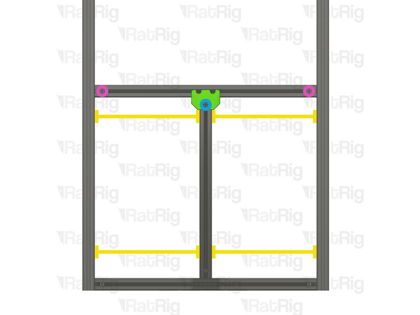
Move the Frame Jig to the marked position
-
Make sure the Frame Jig is installed completely flush with the extrusion and that the bottom "tabs" are within the extrusion slot
-
Measure the marked gap on both sides, they should be equal and measure 255mm
-
V-Core 4.0 - 400: The gaps should measure 305mm
-
V-Core 4.0 - 500: The gaps should measure 355mm
-
Fully tighten the marked Set Screw to secure the extrusions together
-
Do not tighten either of the marked Set Screws at this point, they will be secured in a following step
-
If the extrusion connection is loose after fully tightening the Set Screw, loosen the Set Screw and check that the Quick Connector T-Nut Pin was properly positioned. The connection will not tighten if the "notch" on the pin is not aligned with the Set Screw
-
-
-
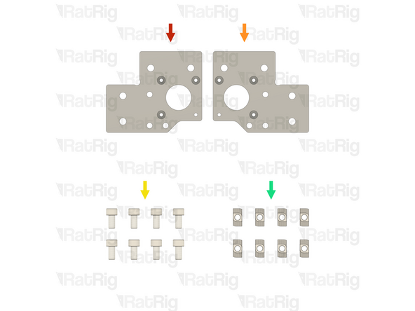
1x Rat Rig V-Core 4.0 - Motor Plate - Lower Left v1.0 (SKU: HW3606PC)
-
1x Rat Rig V-Core 4.0 - Motor Plate - Lower Right v1.0 (SKU: HW3607PC)
-
8x M6x12 Cap Head Screw (SKU: HW1836SC)
-
8x T-Nut Drop-in for 30 series - M6 (SKU: HW1361NC)
-
-
-
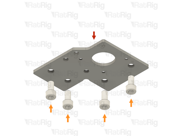
Rat Rig V-Core 4.0 - Motor Plate - Lower Left v1.0
-
4x M6x12 Cap Head Screw
-
Insert the M6x12 Cap Head Screws into the plate from the side without the countersunk holes
-
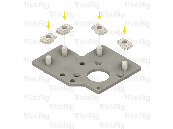
4x T-Nut Drop-in for 30 series - M6
-
Loosely thread a T-Nut onto each of the M6x12 Cap Head Screws. Do not tighten them at this point
-
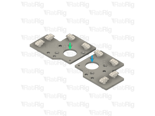
Repeat these instructions to assemble the lower right stepper motor plate
-
Completed lower left stepper motor plate
-
Completed lower right stepper motor plate
-
-
-
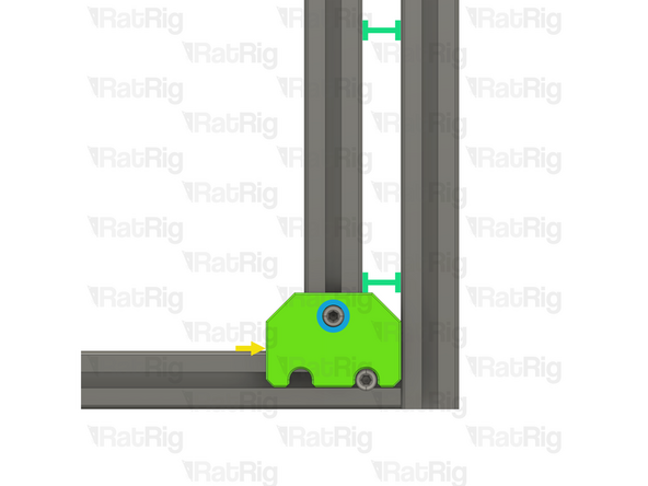
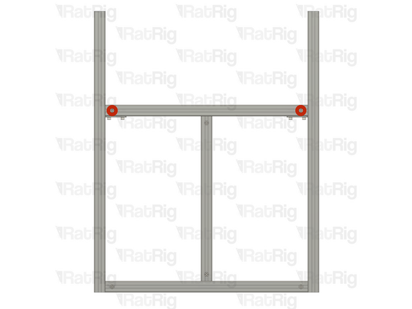
Align the lower left stepper motor plate assembly with the back left extrusion as shown
-
Make sure the plate is fully seated against the 3030 extrusion
-
Raise the plate upwards until it touches the extrusions above
-
Tighten the four M6x12 Cap Head Screws to secure the stepper motor plate to both extrusions. This will ensure the side and back extrusions are correctly aligned
-
Repeat the above instructions to align and install the lower right stepper motor plate assembly to the frame
-
-
-
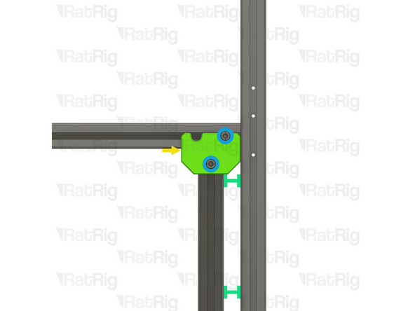
Fully tighten the marked Set Screws to secure the rear extrusion to the frame
-
If the extrusion connection is loose after fully tightening the Set Screw, loosen the Set Screw and check that the Quick Connector T-Nut Pin was properly positioned. The connection will not tighten if the "notch" on the pin is not aligned with the Set Screw
-
Loosen all four M6x12 Cap Head Screws on the lower left stepper motor plate, and remove it from the frame
-
Loosen all four M6x12 Cap Head Screws on the lower right stepper motor plate, and remove it from the frame
-
Set both stepper motor plates aside, they will be used later in the guide
-
-
-
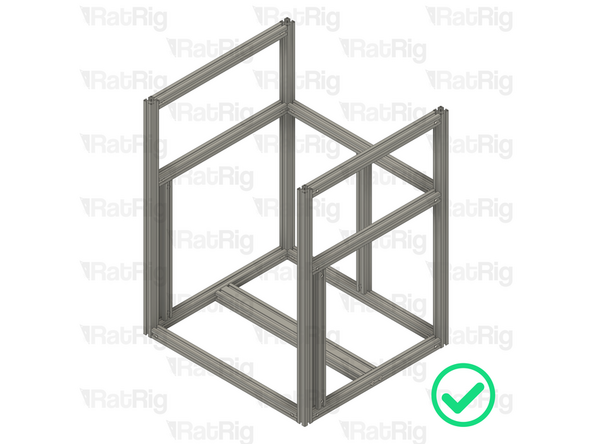
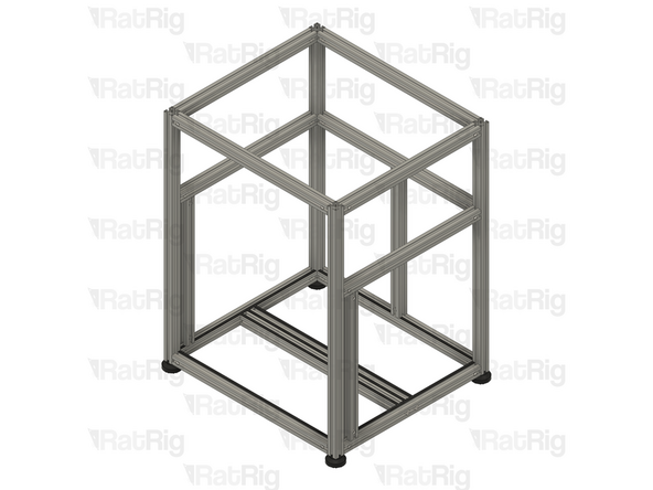
It is important to verify the frame assembly is correct at this point. Check the following:
-
The front extrusions are installed correctly with the three M3 holes at the top and facing towards the sides
-
The two M8x40 Cap Head Screws per side are fully tightened
-
All of the Quick Connector Set Screws are facing outwards and are fully tightened
-
-
-
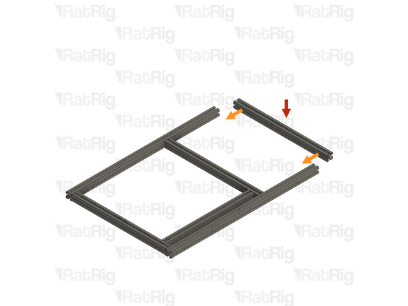
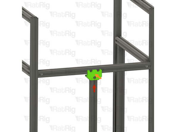
T-Slot 3030 Milled Extrusion - 540mm with Quick Connectors from step 9
-
Insert the extrusion into the side assemblies, making sure the Quick Connector T-Nut Pins are aligned with the side extrusion slots and the Quick Connector Set Screws are facing towards the rear
-
Be careful not to scratch the aluminium extrusions when assembling them
-
Align the extrusions as shown - making sure the ends are flush
-
Refer to step 12 for instructions on how to correctly align the extrusions
-
Fully tighten both of the marked Set Screws to secure the extrusions together
-
If any of the extrusion connections are loose after fully tightening the Set Screws, loosen the Set Screw on the loose joint and check that the Quick Connector T-Nut Pin was properly positioned. The connection will not tighten if the "notch" on the pin is not aligned with the Set Screw
-
-
-
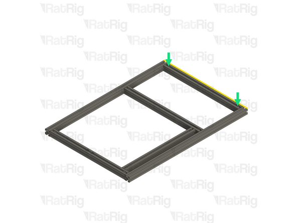
T-Slot 3030 Milled Extrusion - 540mm with Quick Connectors from step 9
-
Insert the extrusion into the side assemblies, making sure the Quick Connector T-Nut Pins are aligned with the side extrusion slots and the Quick Connector Set Screws are facing towards the front
-
Be careful not to scratch the aluminium extrusions when assembling them
-
Align the extrusions as shown - making sure the ends are flush
-
Refer to step 12 for instructions on how to correctly align the extrusions
-
Fully tighten both of the marked Set Screws to secure the extrusions together
-
If any of the extrusion connections are loose after fully tightening the Set Screws, loosen the Set Screw on the loose joint and check that the Quick Connector T-Nut Pin was properly positioned. The connection will not tighten if the "notch" on the pin is not aligned with the Set Screw
-
-
-
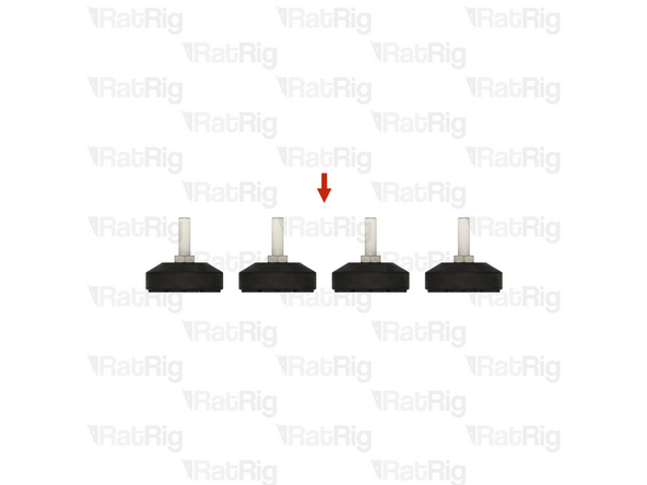
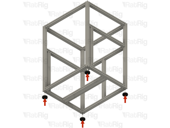
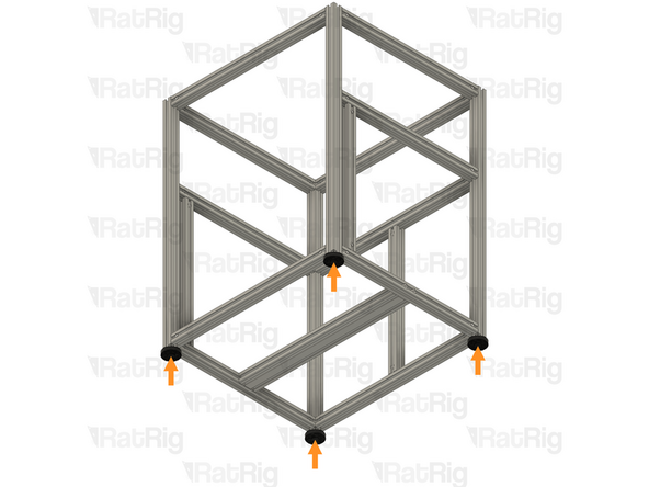
4x Leveling Feet for 3030 - M8x30mm
-
Carefully thread one foot into each of the four frame corner extrusions as shown
-
Adjust each foot so that the frame sits level and does not wobble
-
-
-
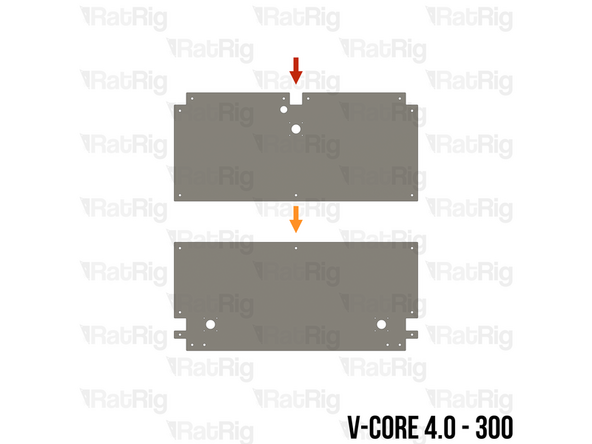
The SKUs for the V-Core 4.0 base plates vary depending on the size:
-
V-Core 4.0 - 300: Rat Rig V-Core 4.0 - Base Plate - 300 Rear v1.2 (SKU: HW3919PC)
-
V-Core 4.0 - 300: Rat Rig V-Core 4.0 - Base Plate - 300 Front v1.2 (SKU: HW3918PC)
-
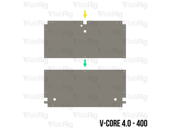
V-Core 4.0 - 400: Rat Rig V-Core 4.0 - Base Plate - 400 Rear v1.2 (SKU: HW3921PC)
-
V-Core 4.0 - 400: Rat Rig V-Core 4.0 - Base Plate - 400 Front v1.2 (SKU: HW3920PC)
-
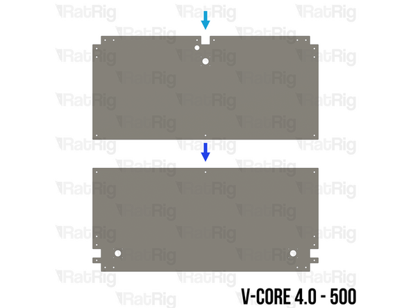
V-Core 4.0 - 500: Rat Rig V-Core 4.0 - Base Plate - 500 Rear v1.2 (SKU: HW3921PC)
-
V-Core 4.0 - 500: Rat Rig V-Core 4.0 - Base Plate - 500 Front v1.2 (SKU: HW3922PC)
-
-
-
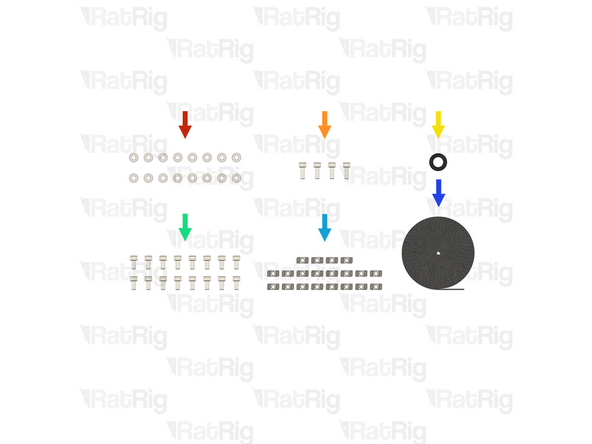
16x Washer Simple M6 - Black 12.9 Steel (SKU: HW2746NC)
-
4x M6x16 Cap Head Screw (SKU: HW2827SC)
-
1x Rubber Grommet - 18x14x3 (SKU: HW3783GC)
-
16x M6x12 Cap Head Screw (SKU: HW1836SC)
-
20x T-Nut - Drop In Type for 30 Series - M6 (SKU: HW1361NC)
-
22 Metres of Foam Strip - 1mm x 8mm - Adhesive 3M - EVA material (SKU: HW2943GC)
-
-
-
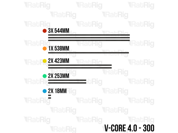
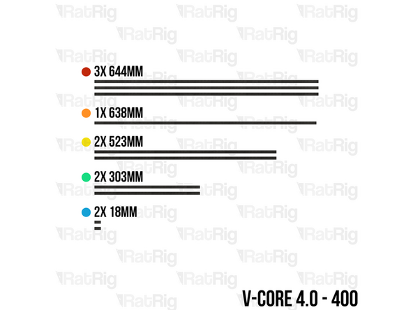
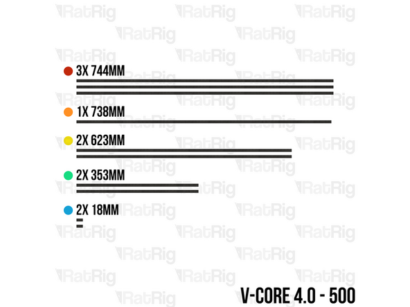
Using scissors, cut lengths of the foam strip based upon the size of the V-Core 4.0 being assembled:
-
3x 544mm (300) / 644mm (400) / 744mm (500)
-
1x 538mm (300) / 638mm (400) / 738mm (500)
-
2x 423mm (300) / 523mm (400) / 623mm (500)
-
2x 253mm (300) / 303mm (400) / 353mm (500)
-
2x 18mm (All sizes)
-
-
-
For each length of foam strip, carefully remove the backing paper which protects the adhesive and then apply it to the frame in the positions shown:
-
544mm (300) / 644mm (400) / 744mm (500)
-
538mm (300) / 638mm (400) / 738mm (500)
-
423mm (300) / 523mm (400) / 623mm (500)
-
253mm (300) / 303mm (400) / 353mm (500)
-
18mm (All sizes)
-
-
-
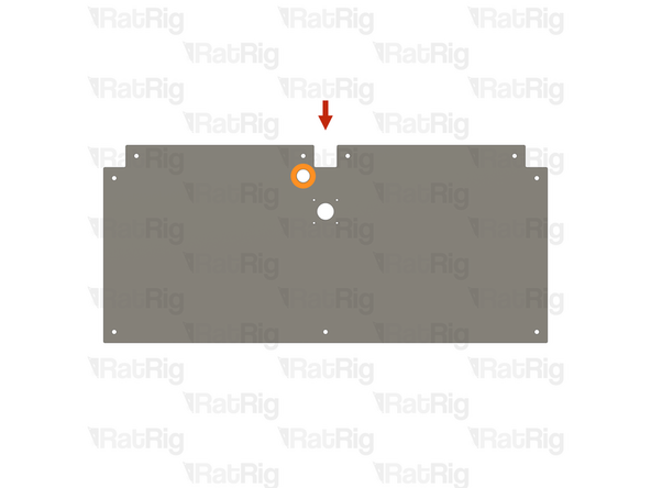
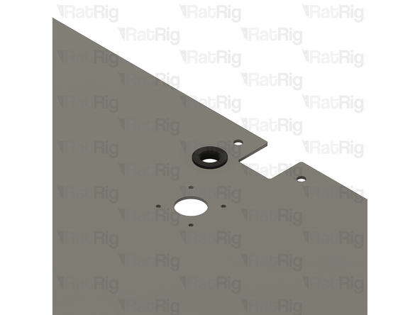
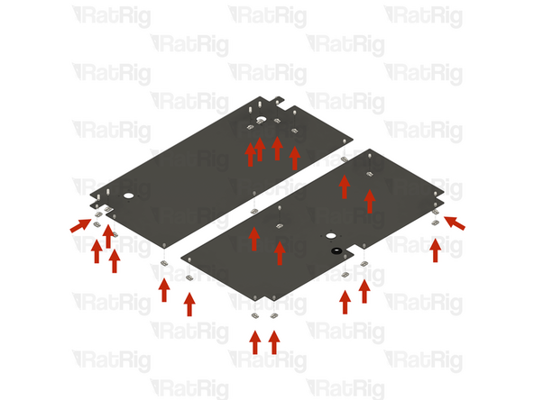
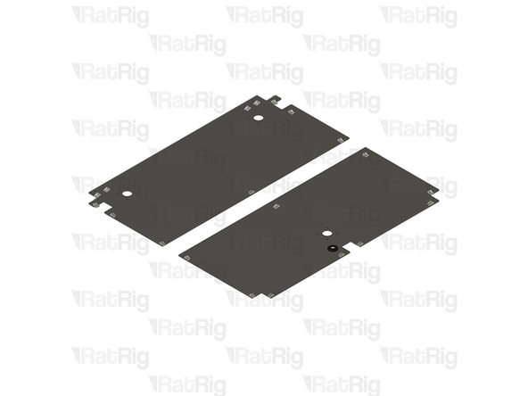
Rat Rig V-Core 4.0 - Base Plate - Rear
-
Locate the marked hole on the base plate
-
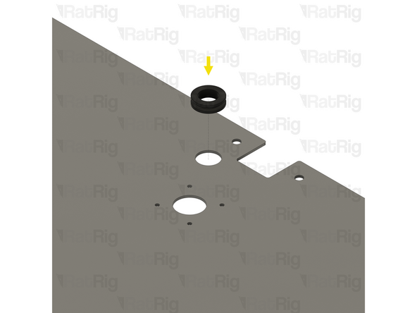
Rubber Grommet - 18x14x3
-
Install the Rubber Grommet into the marked hole. The grommet is flexible so it can be deformed to install it
-
-
-
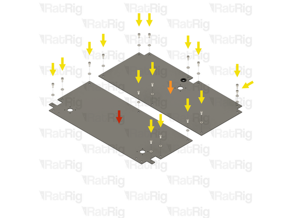
Rat Rig V-Core 4.0 - Base Plate - Rear
-
Make sure the rear base plate is oriented with the grommet offset to the left
-
Rat Rig V-Core 4.0 - Base Plate - Front
-
16x M6x12 Cap Head Screw
-
16x Washer Simple M6 - Black 12.9 Steel
-
Install an M6 washer onto each of the M6x12 Cap Head Screws and then insert the screw into each of the holes shown
-
4x M6x16 Cap Head Screw
-
Insert an M6x16 Cap Head Screw into each of the four holes along the front edge of the front base plate
-
-
-
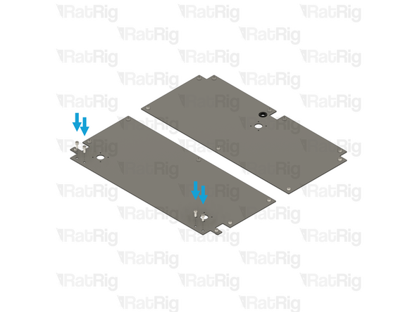
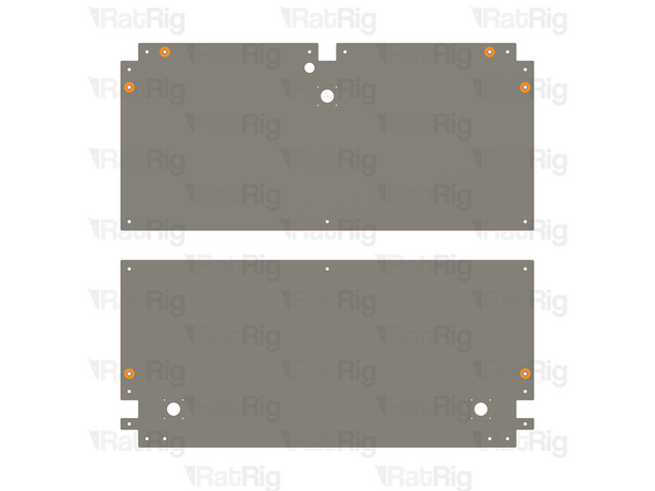
20x T-Nut Drop-in for 30 series - M6
-
Loosely thread a 3030 T-nut onto each of the sixteen M6x12 Cap Head Screws and onto each of the four M6x16 Cap Head Screws. Do not tighten any of them at this point
-
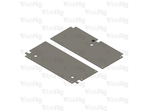
Please note: The base plates for both the V-Core 4.0 400 and V-Core 4.0 500 have six additional mounting holes which are not used in the default kit
-
These additional holes are provided to allow the optional installation of extra brackets for increased frame stiffness
-
-
-
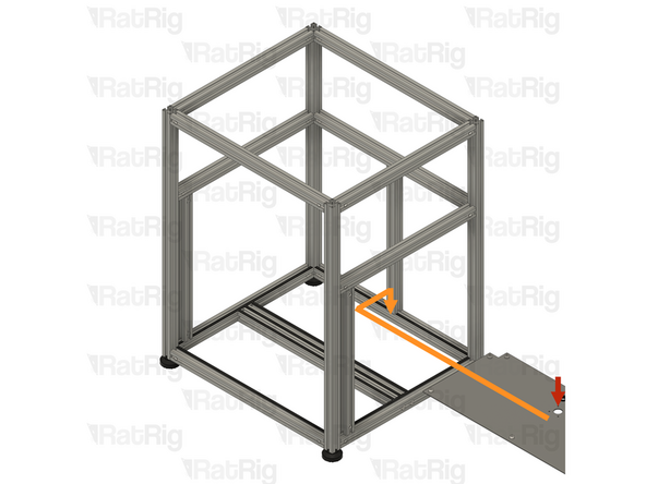
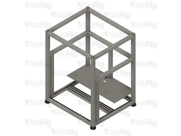
Rear Base Plate assembly from the previous step
-
Insert the Rear Base Plate into the side of the frame assembly, sliding it to the back, and then downwards to rest on the base of the frame assembly
-
Be careful not to scratch the aluminium extrusions when installing the Rear Base Plate
-
Make sure all of the T-Nuts are slotted into the extrusions
-
Secure the Rear Base Plate to the frame assembly by tightening all nine M6x12 screws
-
The ninth screw is obscured in the image
-
-
-
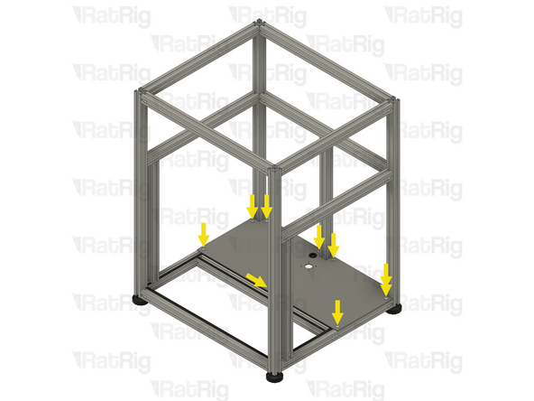
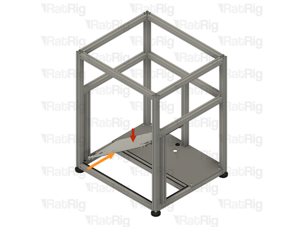
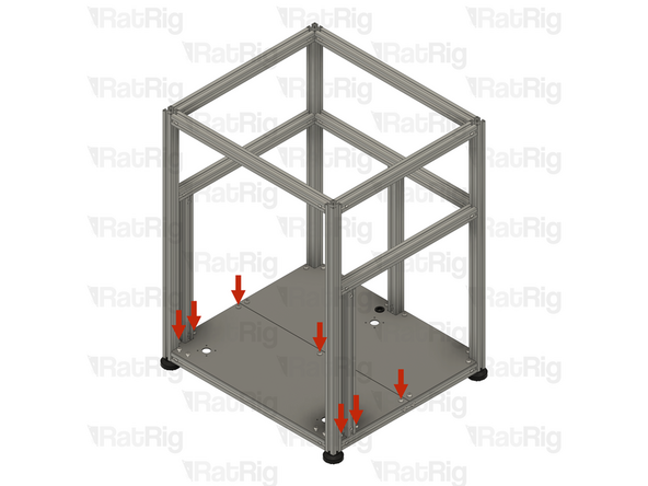
Front Base Plate assembly from step 46
-
Insert the Front Base Plate into the front of the frame assembly, at a 45-degree angle
-
Move the left-hand side of the Front Base Plate into position above the bottom left-hand side extrusions
-
Rotate the right-hand side of the Front Base Plate downwards until it sits flat within the frame assembly
-
Be careful not to scratch the aluminium extrusions when installing the Front Base Plate
-
Make sure all of the T-Nuts are slotted into the extrusions
-
-
-
Make sure that the Front Base Plate is fully seated in the base of the frame assembly
-
Secure the Front Base Plate to the frame assembly by tightening all seven M6x12 screws
-
Do not tighten the four M6x16 Cap Head Screws along the front edge at this point
-
-
-
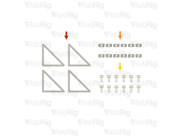
4x Bracket - Extruded 90º Corner for 30 series - 6030 Tall - Black (SKU: HW3162BC)
-
12x T-Nut - Drop In Type for 30 Series - M6 (SKU: HW1361NC)
-
12x M6x12 Cap Head Screw (SKU: HW1836SC)
-
-
-
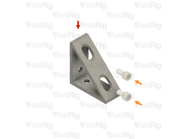
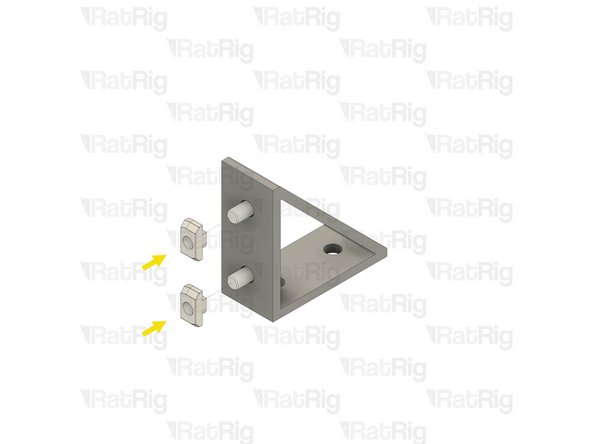
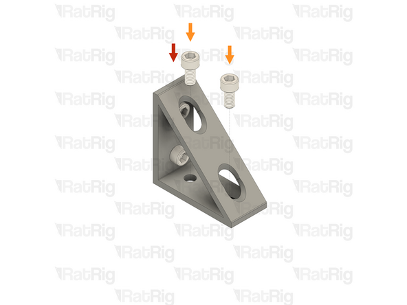
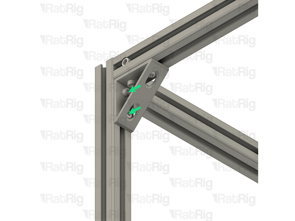
Bracket - Extruded 90º Corner for 30 series - 6030 Tall - Black
-
2x M6x12 Cap Head Screw
-
Insert an M6x12 Cap Head Screw into each of the two holes on one side of the bracket as shown
-
2x T-Nut - Drop In Type for 30 Series - M6
-
Loosely thread a 3030 T-nut onto each of the two M6x12 Cap Head Screws. Do not tighten any of them at this point
-
Prepare four of these assemblies. Set two aside until step 53 and keep two for the next step
-
-
-
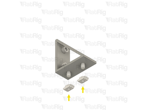
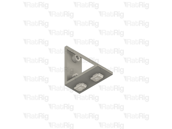
Lower frame bracket assemble from the previous step
-
2x M6x12 Cap Head Screw
-
Insert an M6x12 Cap Head Screw into each of the two holes on the remaining side of the bracket as shown
-
2x T-Nut - Drop In Type for 30 Series - M6
-
Loosely thread a 3030 T-nut onto each of the two M6x12 Cap Head Screws. Do not tighten any of them at this point
-
Prepare two of these assemblies and set them both aside until step 55
-
-
-
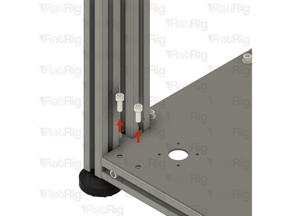
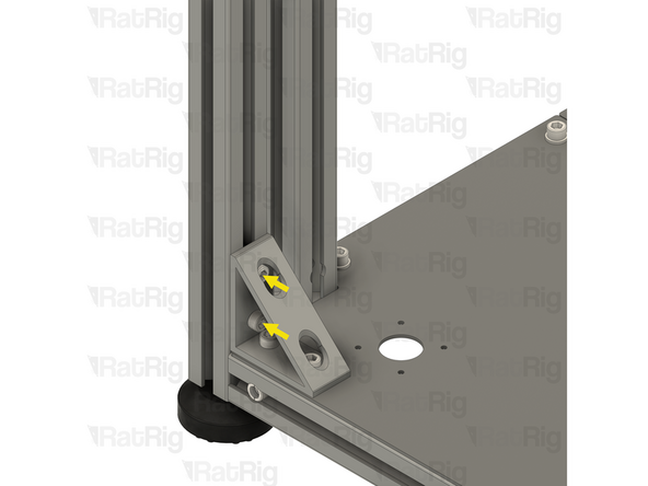
2x M6x16 Cap Head Screw
-
Carefully unscrew and remove both M6x16 Cap Head Screws, set them aside for a moment
-
It is important not to move the T-Nuts hidden under the Base Plate
-
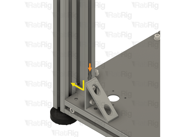
Lower frame bracket assembly from step 51
-
Position the lower frame bracket as shown. The bottom holes in the bracket should align with the holes in the Base Plate
-
Make sure both of the T-Nuts are slotted into the extrusion
-
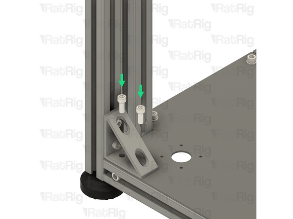
Insert the two M6x16 Cap Head Screws into the lower frame bracket and loosely thread them back into the T-Nuts under the Base Plate
-
Do not tighten any of the M6x12 or M6x16 Cap Head Screws at this point
-
-
-
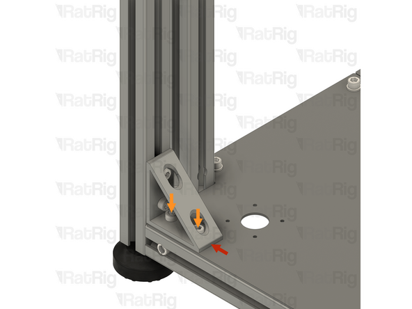
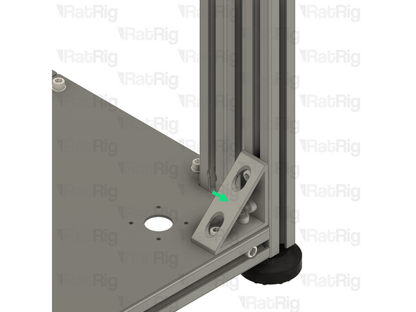
Press the lower frame bracket against the side 3030 extrusion
-
Fully tighten both of the M6x16 Cap Head Screws to secure the lower frame bracket to the Base Plate
-
Fully tighten both of the M6x12 Cap Head Screws to secure the lower frame bracket to the 3030 extrusion
-
Repeat both the previous step, and this step, to install the lower right frame bracket
-
-
-
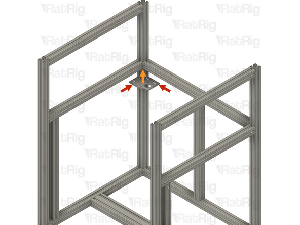
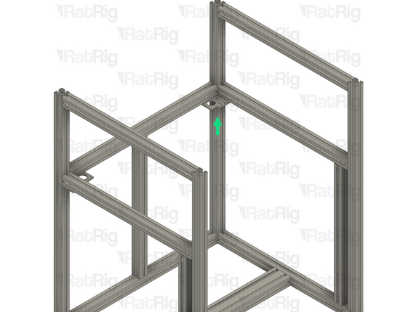
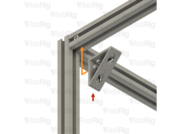
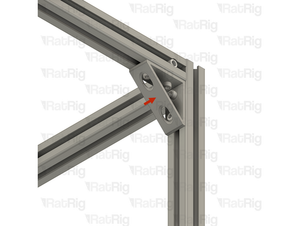
Upper frame bracket assembly from step 52
-
Position the upper frame bracket into the corner of the extrusions as shown
-
Make sure all of the T-Nuts are slotted into the extrusions
-
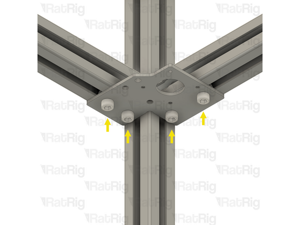
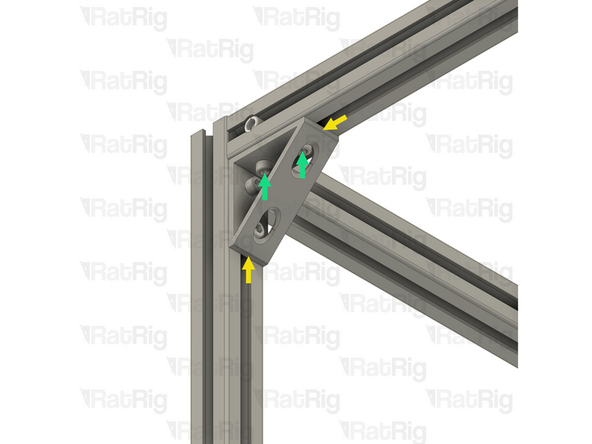
Press the upper frame bracket into the corner of the 3030 extrusions
-
Fully tighten all four of the M6x12 Cap Head Screws to secure the upper frame bracket to the frame
-
-
-
Repeat the previous step, to install the upper right frame bracket
-
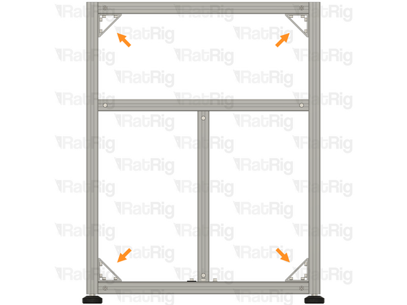
Verify that all 4 frame brackets are correctly installed and that all Cap Head Screws are fully tightened
-


Cancel: I did not complete this guide.
53 other people completed this guide.