
Steps
90
- 02. Enclosure 2.0 Addon 90 steps

User-Contributed Guide
This guide is not managed by the site's staff.
Quiz
0
Introduction
IMPORTANT: Make sure you have the “Rat Rig MGN12 3030 Alignment Tools” before beginning this guide. They are necessary to re-align the linear rails during the upgrade. If you discarded them, or cannot find them, you must print replacements before beginning.
Please note: All measurements provided in this guide are based upon building a 300x300 V-Core 3.
If you are building a machine of a different size, the following adjustments can be made to the stated extrusion lengths:
- 200x200: Remove 100mm
- 400x400: Add 100mm
- 500x500: Add 200mm
-
-
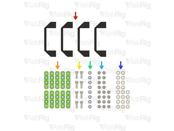
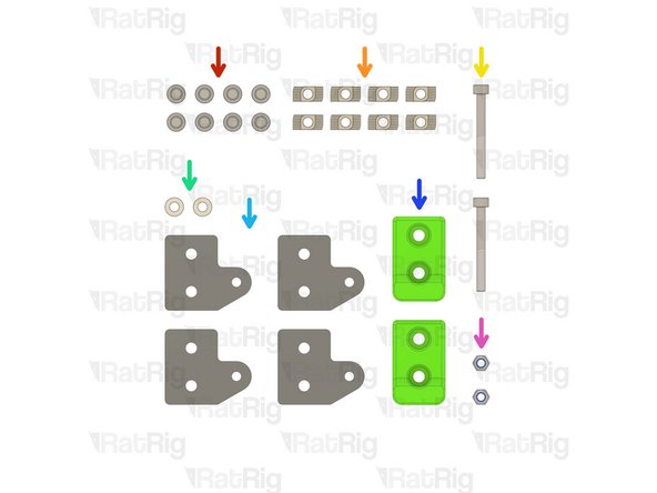
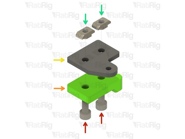
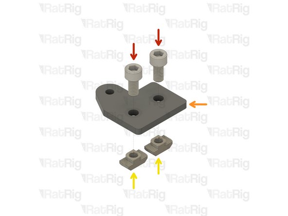
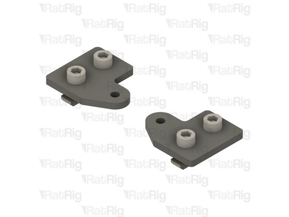
6x T-Shape Joining Plate for 3030
-
30x M6x12 Cap Head Screw
-
30x 3030 Drop-in T-Nut - M6
-
-
-
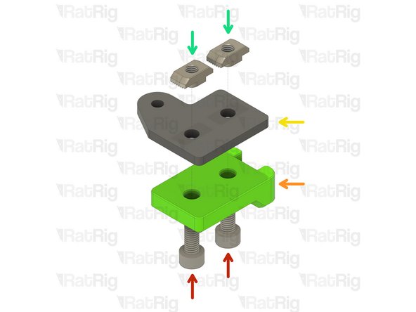
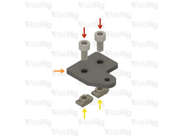
M6x12 Cap Head Screw
-
3030 Drop In T-Nut - M6
-
T-Shape Joining Plate for 3030
-
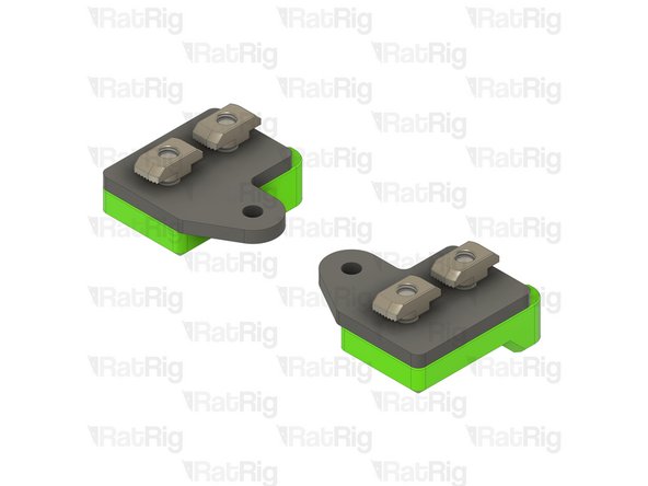
Loosely thread the 3030 T-Nuts onto the M6x12 screws. Do not tighten them at this point.
-
Set these plates aside until Steps 26, 28, 52 & 53
-
-
-
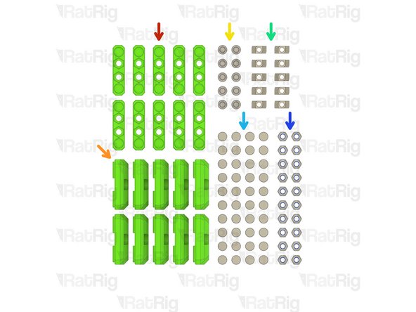
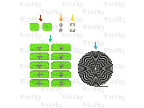
10x panel_magnet_holder printed part
-
10x panel_magnet_mount printed part
-
10x M6x12 Cap Head Screw
-
10x 3030 Drop-in T-Nut - M6
-
40x Neodymium Disc Magnet - 10x4mm
-
20x M6 Nylon Locking Hex Nut
-
-
-
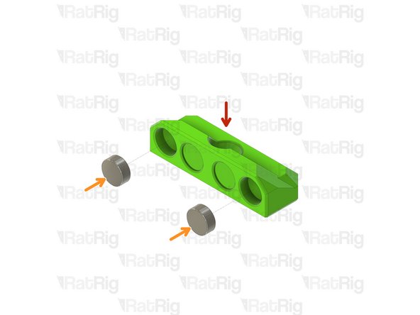
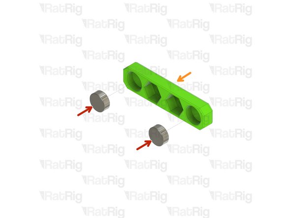
panel_magnet_mount printed part
-
Neodymium Disc Magnet - 10x4mm
-
The magnets are designed to be a tight fit into the printed part. If they are loose, or you wish to secure them further, place a few drops of cyanoacrylate glue into the printed part before adding the magnet
-
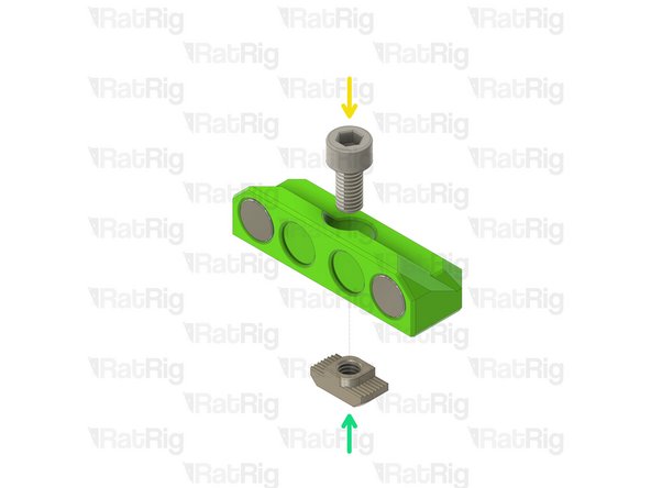
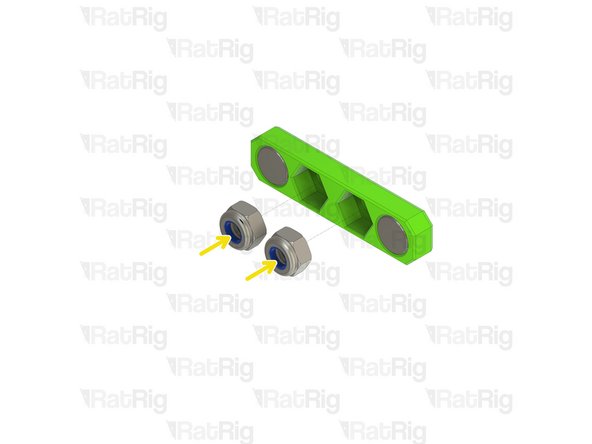
M6x12 Cap Head Screw
-
3030 Drop-in T-Nut - M6
-
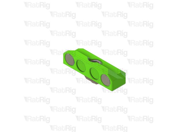
Loosely thread the 3030 T-Nuts onto the M6x12 screws. Do not tighten them at this point.
-
Set these assemblies aside until Steps 82 & 84
-
-
-
panel_magnet_holder printed part
-
Neodymium Disc Magnet - 10x4mm
-
Pay attention to the orientation of the magnets when installing them into the printed parts. Use the assemblies from the previous step to verify the magnets attract to each other, rather than repell from each other!
-
The magnets are designed to be a tight fit into the printed part. If they are loose, or you wish to secure them further, place a few drops of cyanoacrylate glue into the printed part before adding the magnet
-
M6 Nylon Locking Hex Nut
-
Set these assemblies aside until Steps 7, 8 & 11
-
-
-
Rat Rig provides DXF and STEP files for you to have your own panels produced locally. These are available for download on the Rat Rig V-Core 3 GitHub repository
-
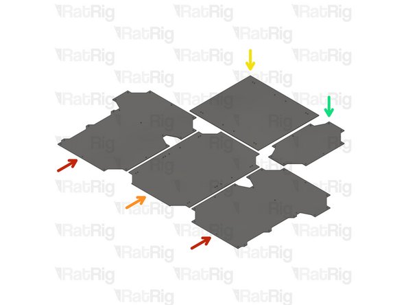
2x panel_enc2_side_size
-
1x panel_enc2_door_size
-
1x panel_enc2_top_size
-
1x panel_enc2_back_size
-
Use the file with the correct size for your printer (200, 300, 400 or 500)
-
-
-
4x Rat Rig nylon door handle
-
10x Panel magnet mount assemblies from Step 5
-
8x M6x16 Cap Head Screw
-
8x M6 Nylon Locking Hex Nut
-
24x M6x12 Cap Head Screw
-
24x M6 Washer
-
-
-
There are 6 magnet mount positions on the door (or 4 on the 200). Repeat the following for each of them
-
panel_enc2_door_size
-
M6x12 Cap Head Screw
-
M6 Washer
-
Panel magnet mount assembly from Step 5
-
Take care not to over tighten the M6x12 screw as you can damage the printed parts
-
-
-
There are 2 handle positions on the door. Repeat the following for each of them
-
panel_enc2_door_size
-
Rat Rig nylon door handle
-
M6x16 Cap Head Screw
-
M6 Nylon Locking Hex Nut
-
Do not overly tighten the M6 nylon locking hex nuts when securing the handles, as this can cause the panel to warp which will prevent a good seal to the printer
-
-
-
Completed door panel assembly
-
Set the completed door assembly aside until Step 85
-
-
-
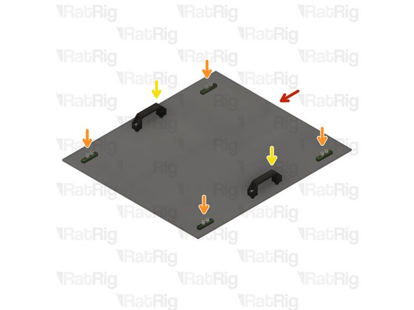
panel_enc2_top_size
-
Install four of the panel magnet mount assemblies to the top panel
-
Take care not to over tighten the M6x12 screw as you can damage the printed parts
-
Install two of the Rat Rig nylon handles to the top panel
-
Do not overly tighten the M6 nylon locking hex nuts when securing the handles, as this can cause the panel to warp which will prevent a good seal to the printer
-
Set the completed top assembly aside until Step 83
-
-
-
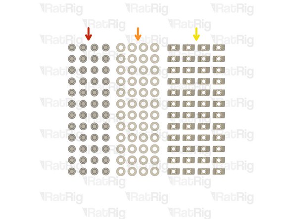
48x M6x12 Cap Head Screw
-
48x M6 Washer
-
48x 3030 Drop-in T-Nut - M6
-
-
-
panel_enc2_side_size
-
M6 Washer
-
M6x12 Cap Head Screw
-
3030 Drop-in T-Nut - M6
-
Loosely thread the 3030 T-Nuts onto the M6x12 screws. Do not tighten them at this point.
-
-
-
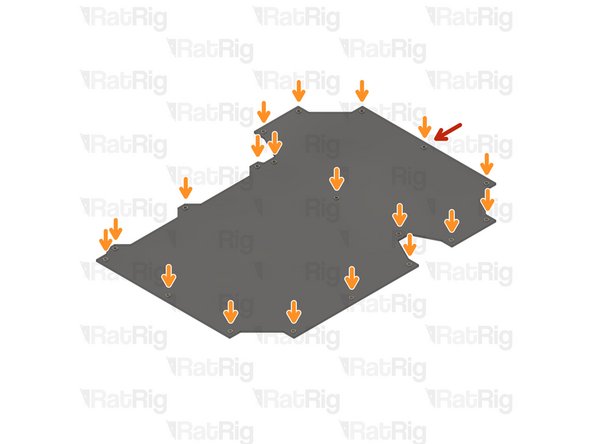
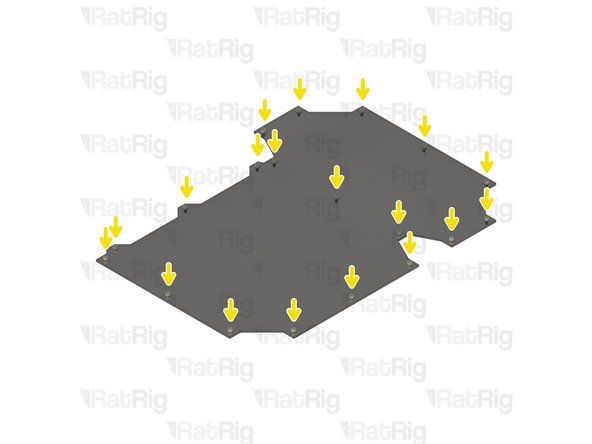
Repeat the previous steps to install an M6x12 cap head screw, M6 washer and 3030 drop-in t-nut to each hole on the remaining panels as shown
-
Set all panels aside until Steps 86, 87 & 88
-
-
-
EVA3 toolhead assembly
-
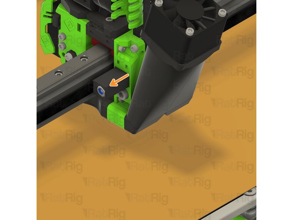
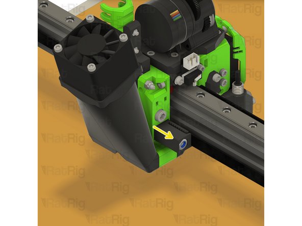
Upper CoreXY belt tensioner
-
Lower CoreXY belt tensioner
-
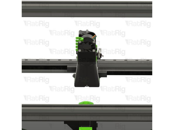
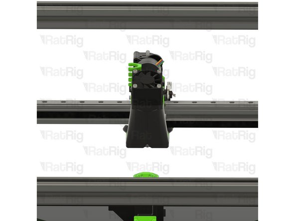
Loosen both CoreXY belt tensioners as shown
-
-
-
Left CoreXY motor assembly
-
M3x35 Cap Head Screw
-
Support the NEMA17 stepper motor whilst removing the M3x35 screws
-
Remove the four M3x35 screws to release the NEMA17 motor
-
Left CoreXY NEMA17 stepper motor
-
Set the 4x M3x35 screws and NEMA17 stepper motor aside until Steps 20 & 21
-
-
-
M5x40 Cap Head Screw
-
Loosen, but do not remove, both of the M5x40 screws
-
-
-
M6x14 Countersink Screw
-
Loosen the three M6x14 screws
-
Lift the upper CoreXY motor cage assembly from the machine
-
Remove all 3 M6x14 screws, and 3030 t-nuts, from the printed part
-
Remove the two M5 nylon locking nuts from the printed part
-
-
-
xy_motor_cage_top_left_3.1_cutout printed part
-
M6x14 Countersink Screw
-
M5 Nylon Locking Hex Nut
-
3030 Drop-in T-Nut - M6
-
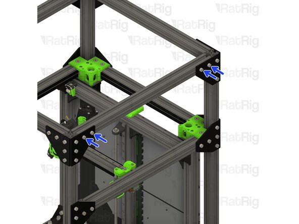
Assemble the new CoreXY motor cage top as shown
-
Install the xy_motor_cage_top_left_3.1_cutout assembly onto the frame as shown
-
Make sure the belt loop remains in the position shown
-
Tighten the three marked M6x14 screws to secure the CoreXY motor cage top to the frame
-
-
-
M5x40 Cap Head Screw
-
Tighten the M5x40 screws to secure the bearing stacks into the CoreXY motor cage top
-
CoreXY NEMA17 stepper motor from Step 16
-
Position the NEMA17 motor up and into the motor cage from below,
-
-
-
Insert the M3x35 screws from Step 16 into the CoreXY motor cage as shown, and fasten them to secure the NEMA17 motor to the mount
-
-
-
Repeat Steps 16 thru 21 to replace the right side CoreXY motor cage top
-
-
-
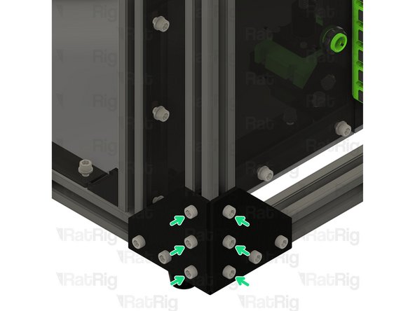
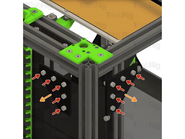
M6x12 Cap Head Screw
-
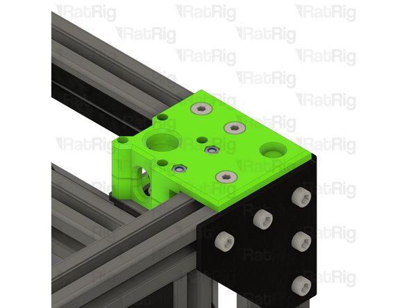
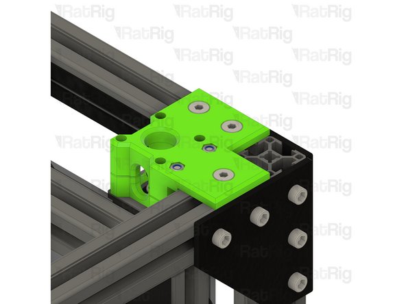
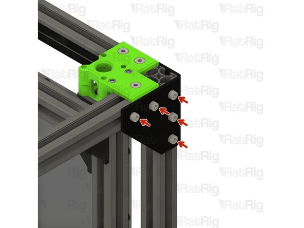
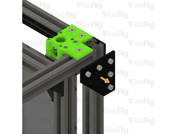
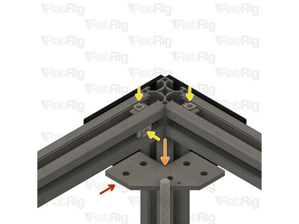
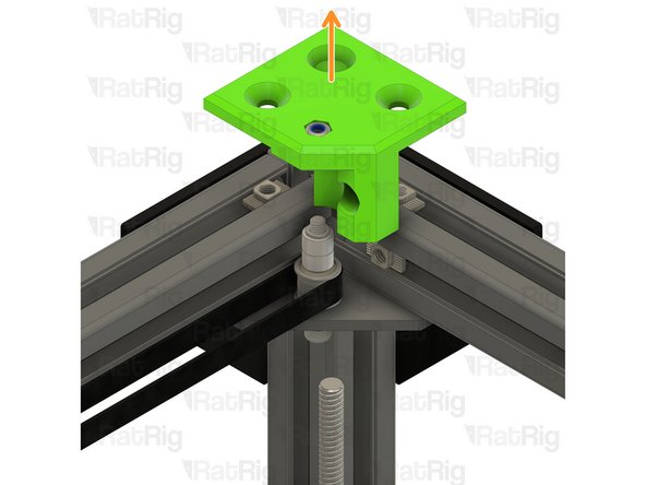
Loosen all of the M6x12 screws and remove the corner plate assembly
-
Loosen all of the M6x12 screws and remove the second corner plate assembly as well
-
Set these corner plate assemblies aside until Steps 72, 73 & 74
-
-
-
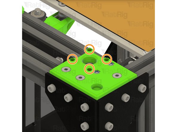
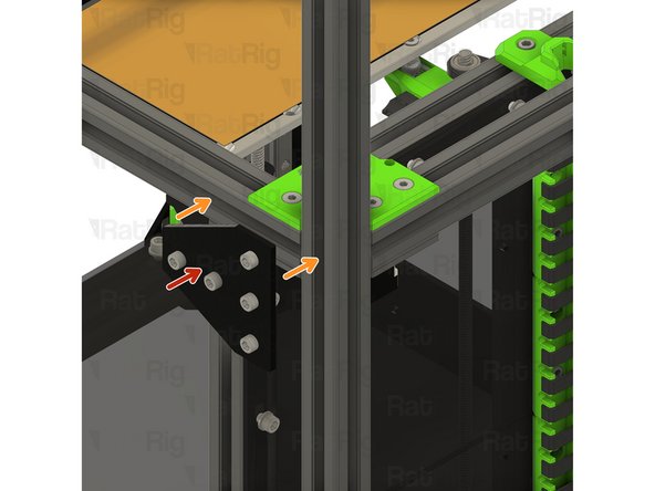
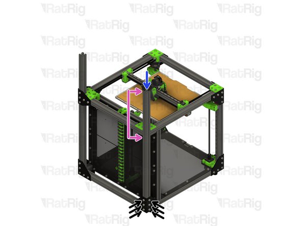
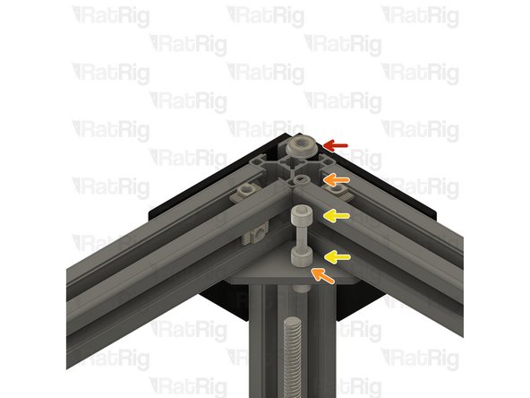
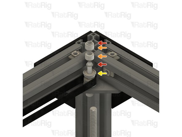
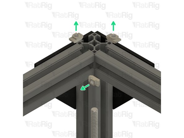
M6x12 Cap Head Screw
-
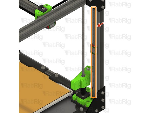
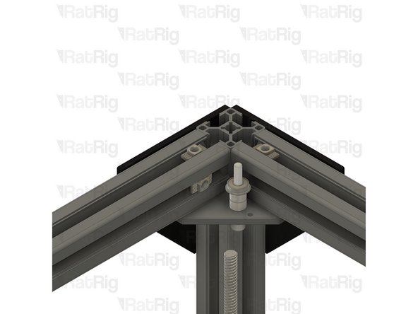
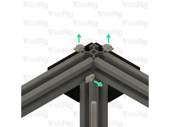
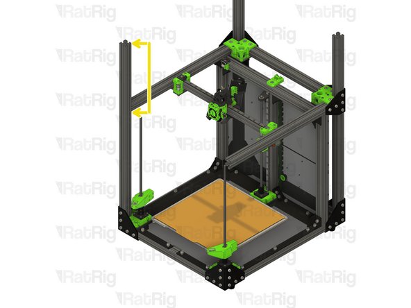
Loosen but do not remove the marked M6x12 screws
-
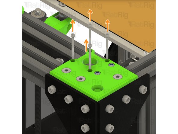
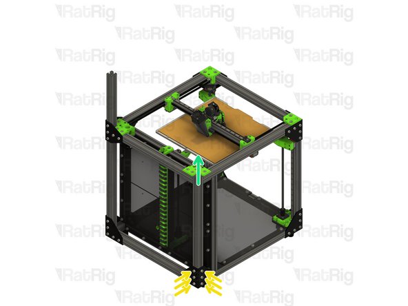
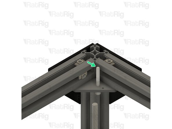
Rear right 3030 extrusion
-
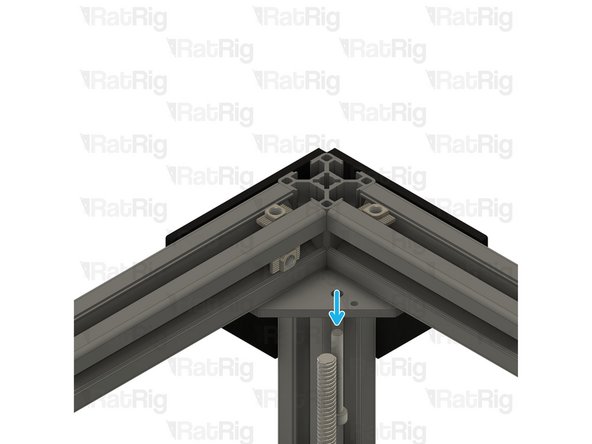
Pull the 3030 extrusion upwards to remove it from the machine frame
-
-
-
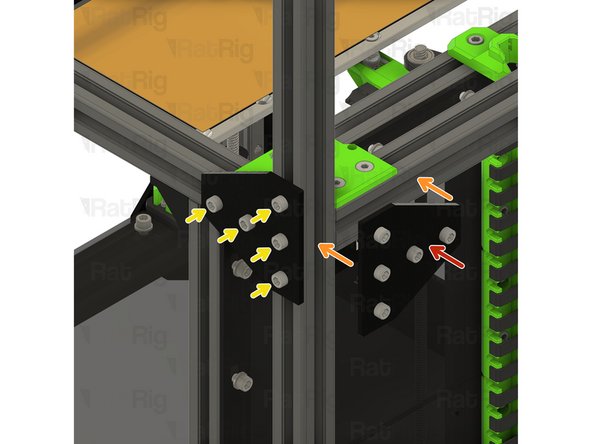
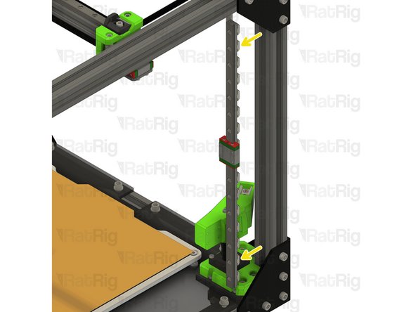
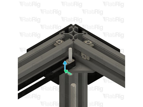
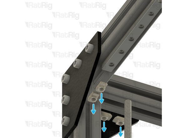
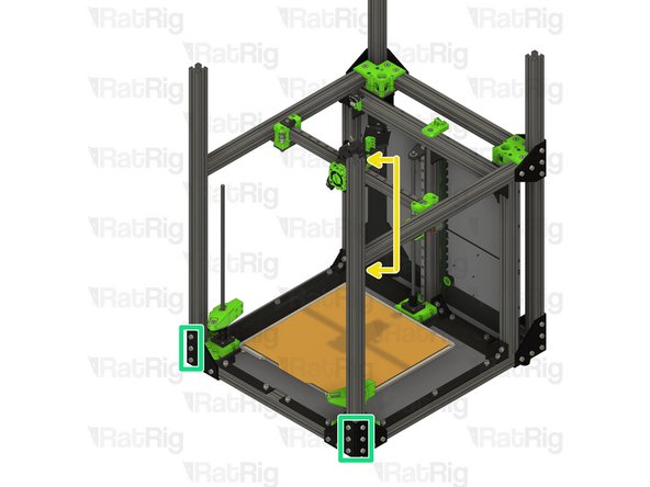
760mm 3030 Extrusion
-
Insert the 3030 extrusion into the bottom corner plate assemblies
-
You may need to rotate the 3030 t-nuts to insert the 3030 extrusion
-
Measure from the underside of the rear extrusion, to the top of the newly installed extrusion. It should measure either 230mm (for a V-Core 3 200) or 280mm (for a V-Core 300, 400 or 500)
-
Ensure the extrusion is fully inserted before continuting
-
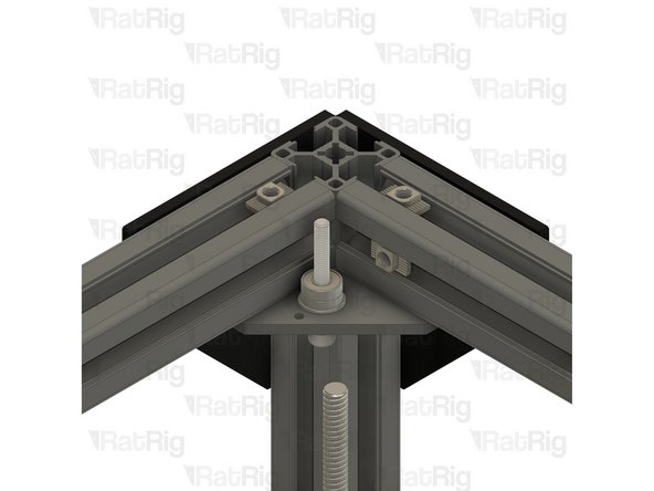
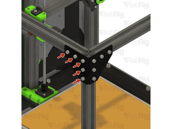
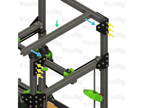
Tighten the six marked M6x12 screws to secure the 3030 extrusion to the frame
-
-
-
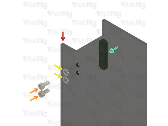
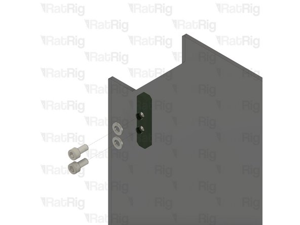
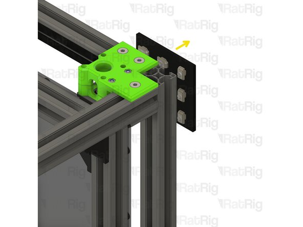
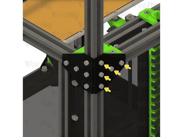
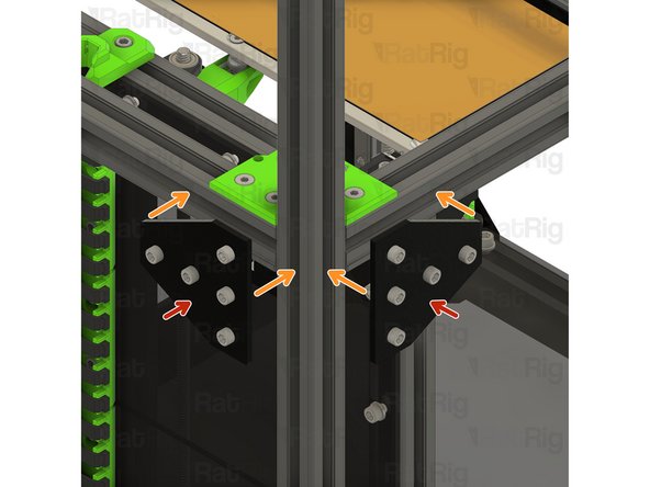
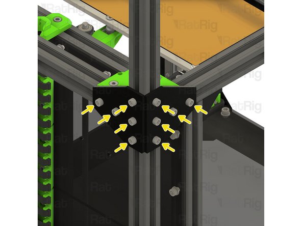
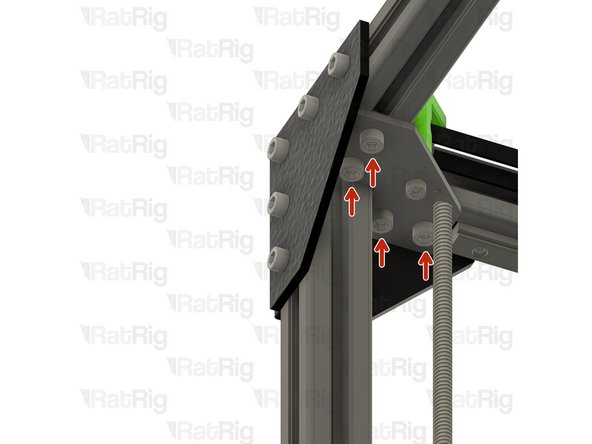
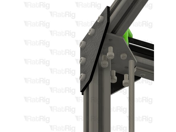
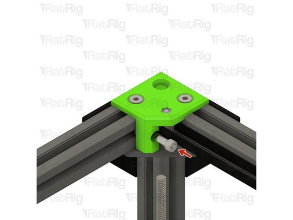
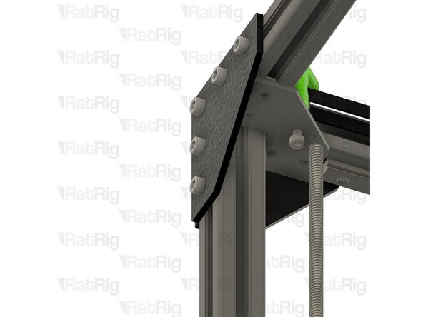
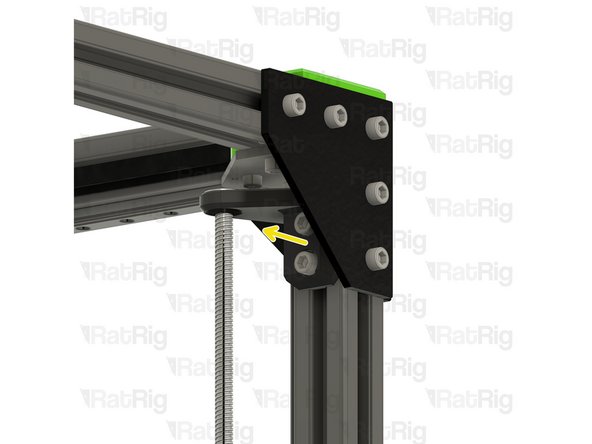
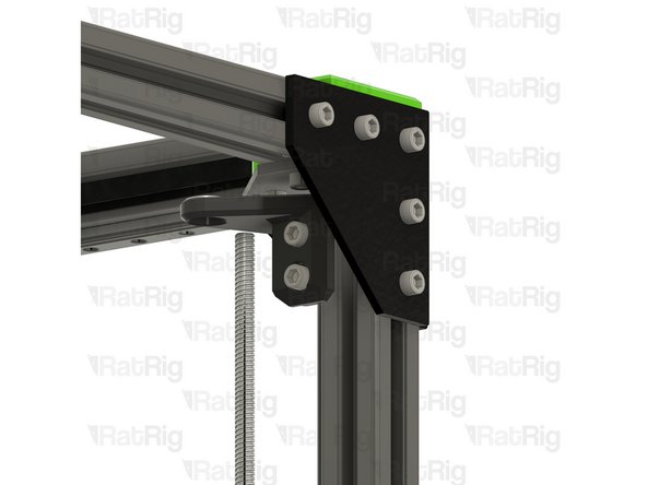
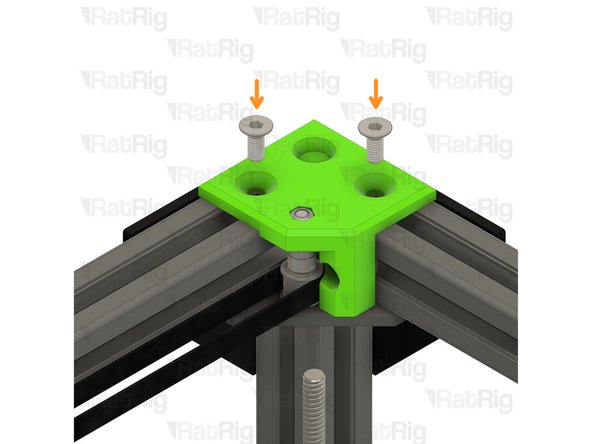
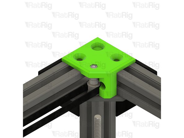
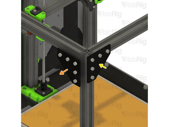
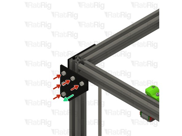
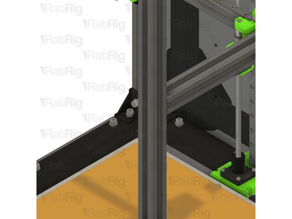
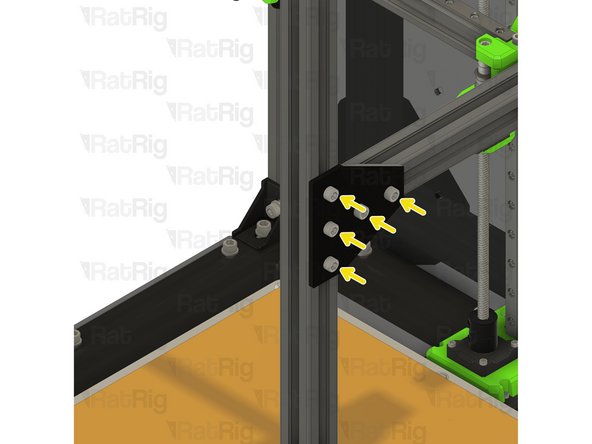
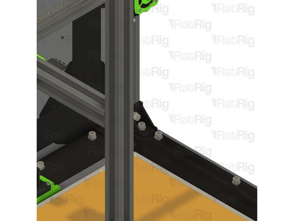
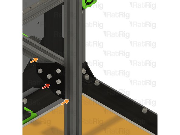
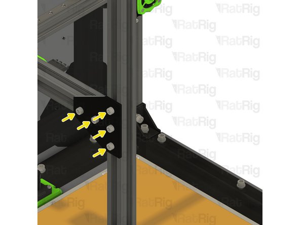
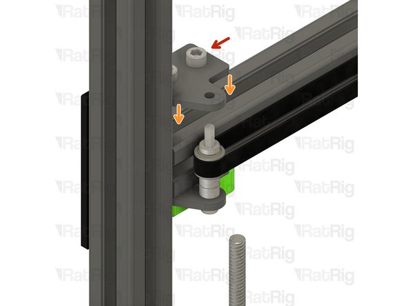
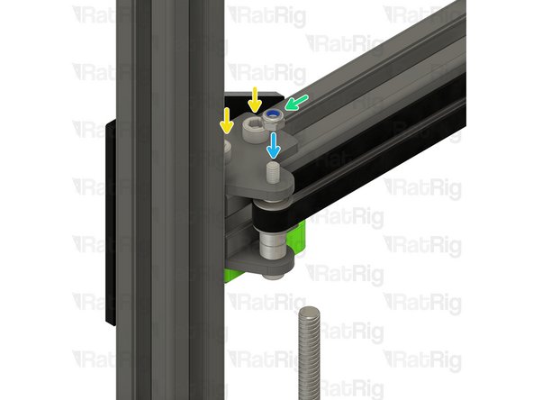
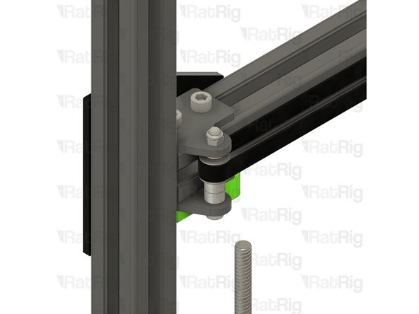
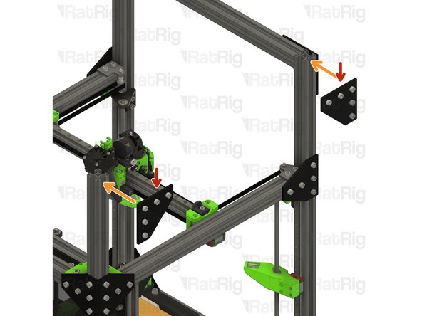
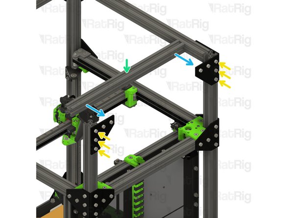
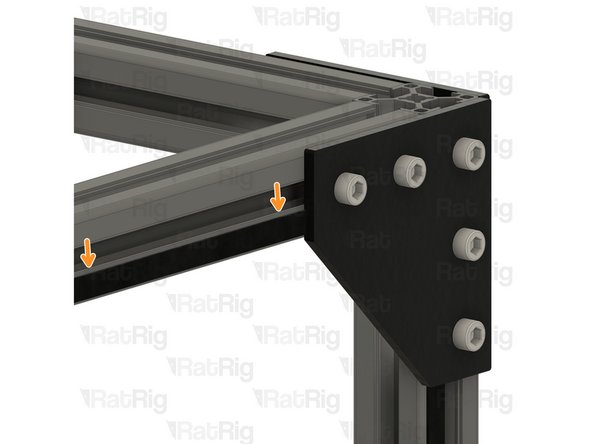
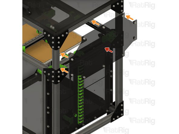
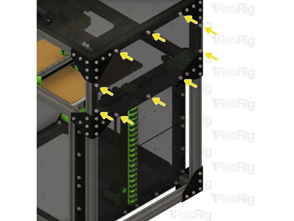
T-Shape plate assembly from Step 2
-
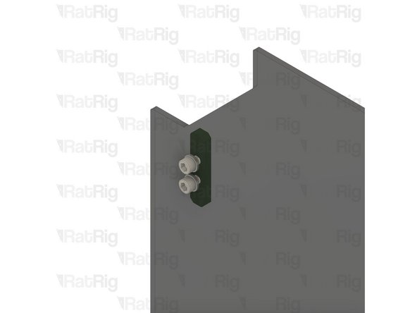
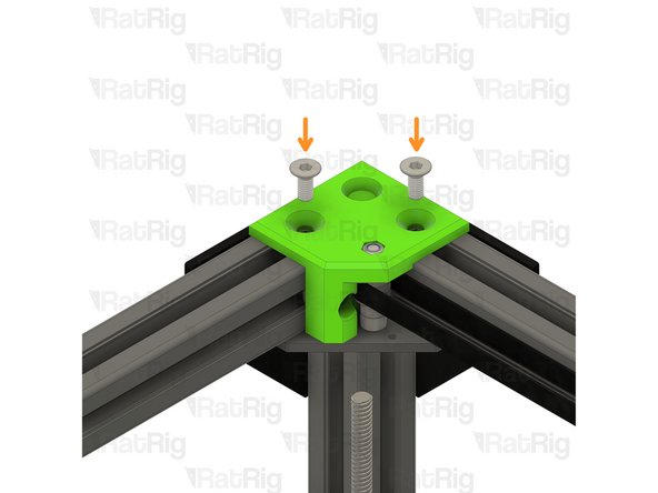
Position the T-shape plates as shown
-
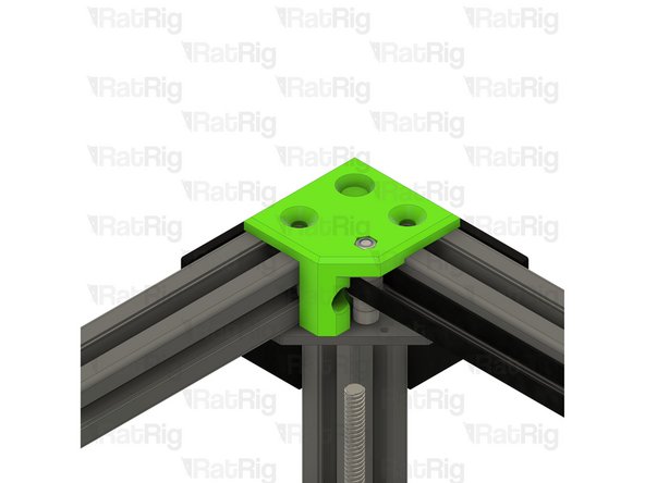
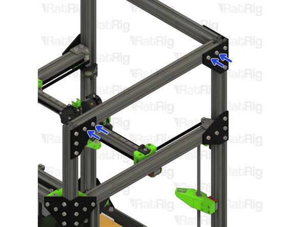
Secure the T-shape plates to the frame by fastening the five M6x12 screws
-
-
-
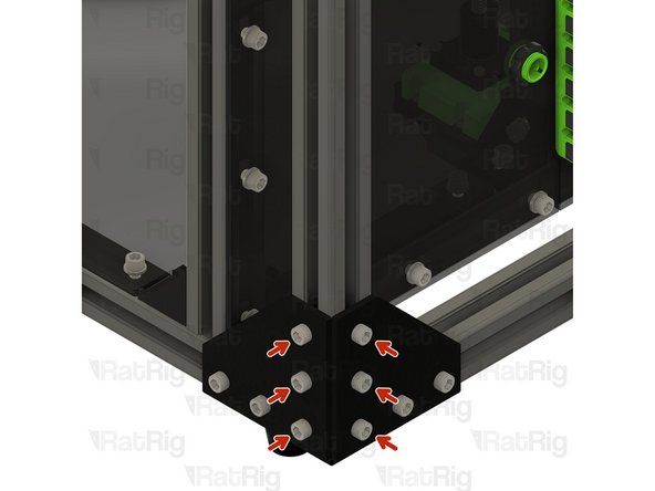
M6x12 Cap Head Screw
-
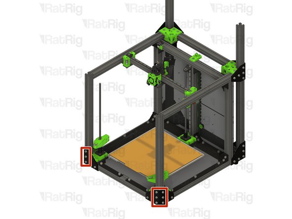
Loosen all of the M6x12 screws and remove both corner plate assemblies
-
Loosen but do not remove the marked M6x12 screws
-
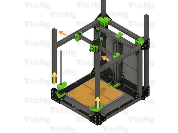
Pull the rear left 3030 extrusion upwards to remove it from the machine frame
-
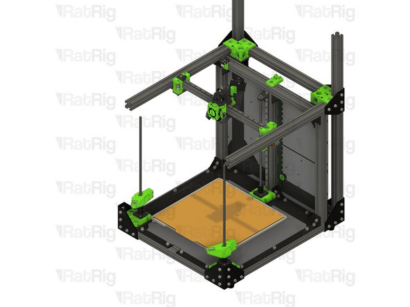
Insert the 760mm 3030 extrusion into the bottom corner plate assemblies
-
You may need to rotate the 3030 t-nuts to insert the 3030 extrusion
-
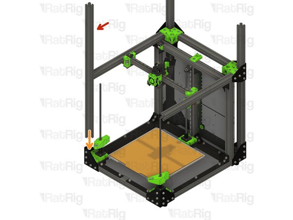
Measure from the underside of the rear extrusion, to the top of the newly installed extrusion. It should measure either 230mm (for a V-Core 3 200) or 280mm (for a V-Core 300, 400 or 500)
-
Tighten the six marked M6x12 screws to secure the 3030 extrusion to the frame
-
-
-
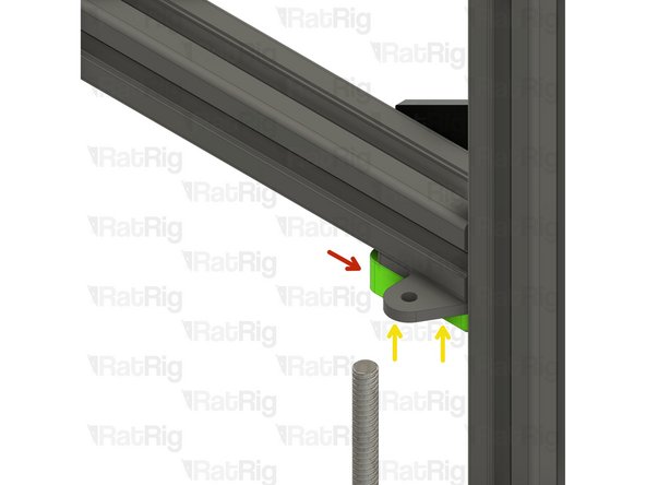
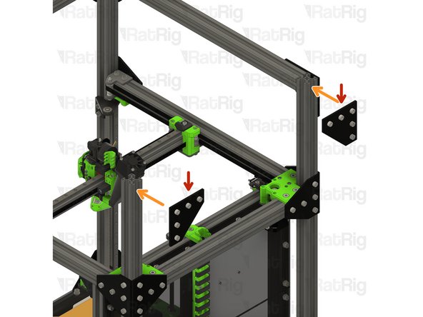
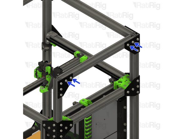
T-Shape plate assembly from Step 2
-
Position the T-shape plates as shown
-
Secure the T-shape plates to the frame by fastening the five M6x12 screws
-
-
-
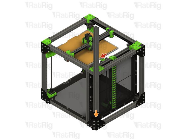
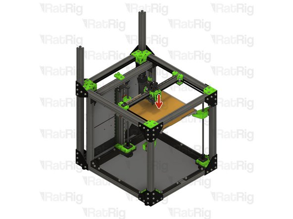
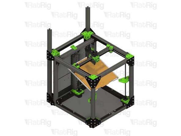
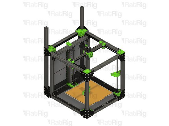
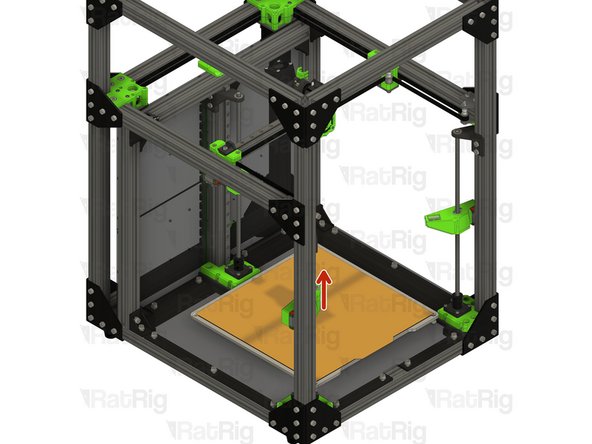
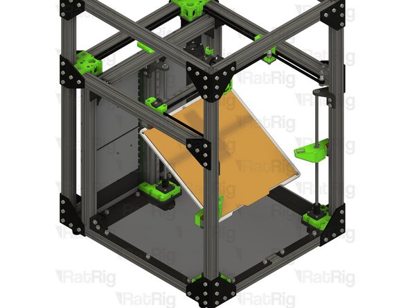
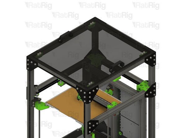
Print bed assembly
-
Lift the print bed assembly off of the bed arms and set it on the base panel (if installed), or the surface the printer sits on
-
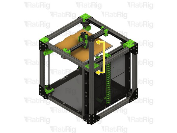
To lower the bed arms, you can manually rotate the leadscrews counter-clockwise
-
-
-
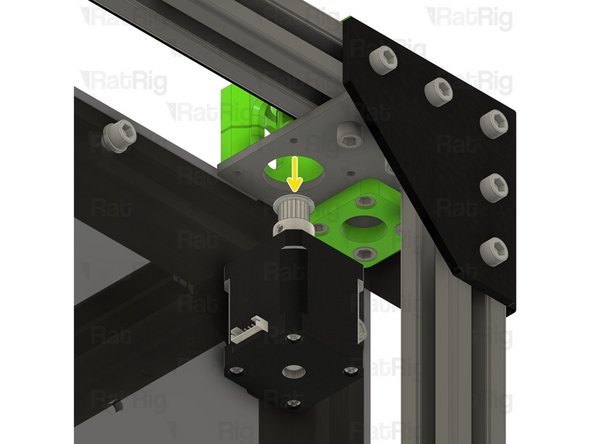
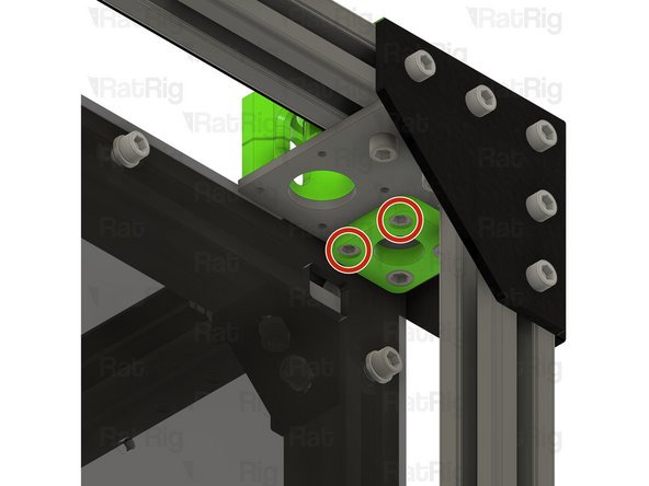
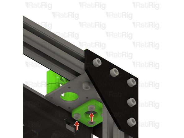
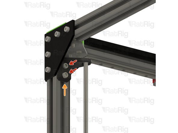
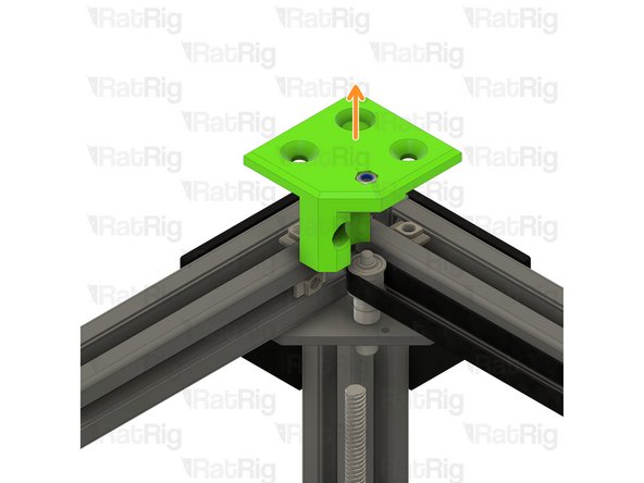
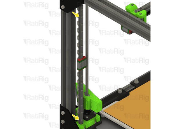
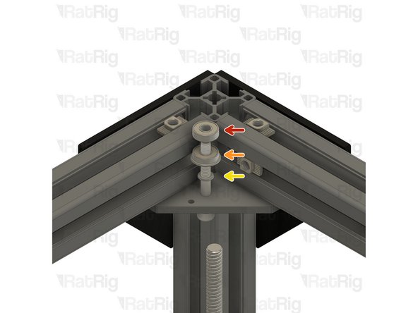
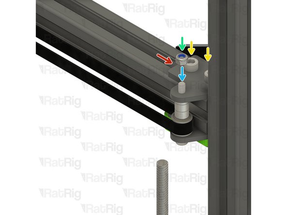
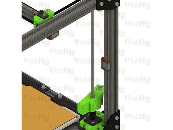
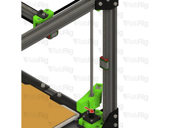
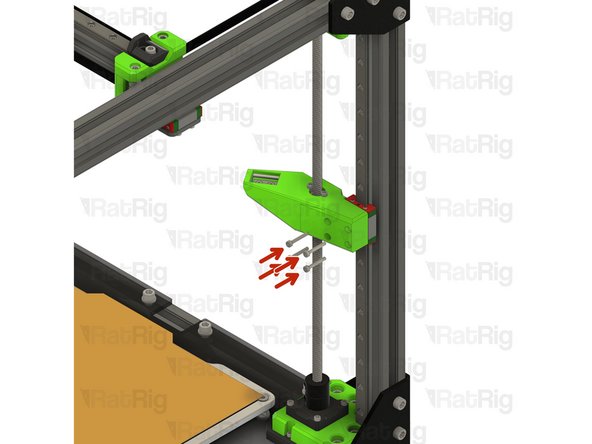
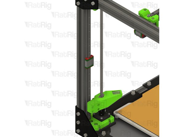
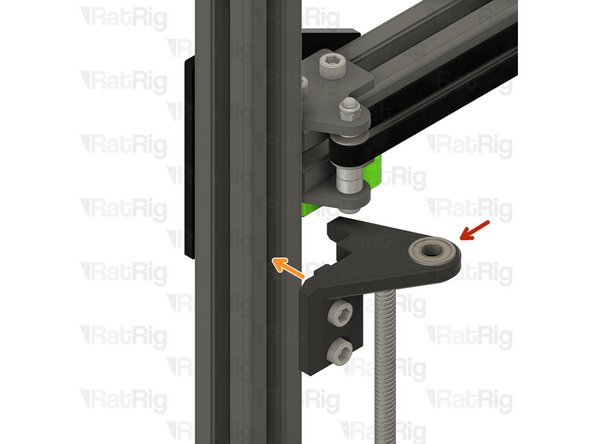
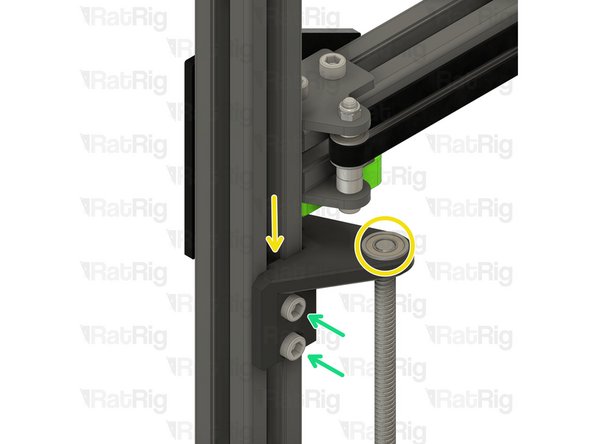
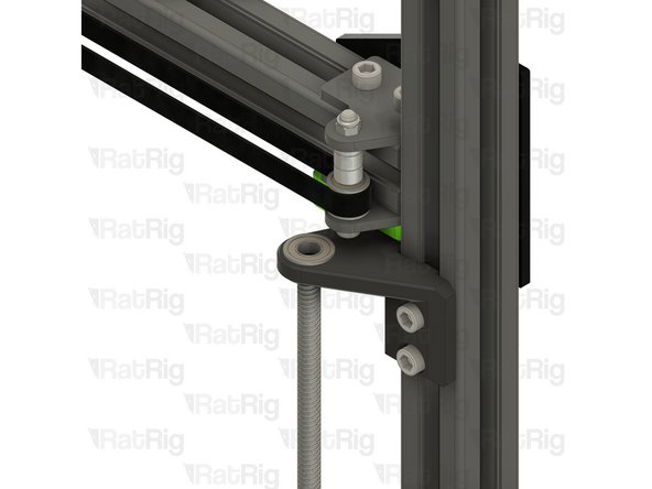
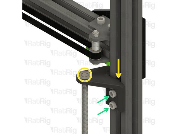
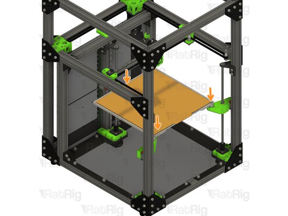
M6x12 Cap Head Screw
-
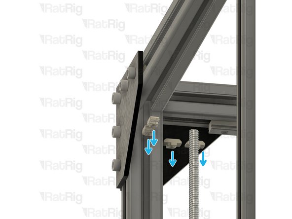
Loosen, but do not remove the two marked M6x12 screws
-
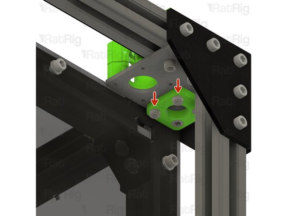
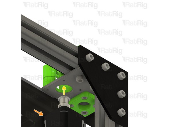
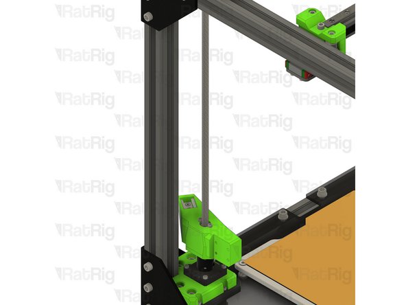
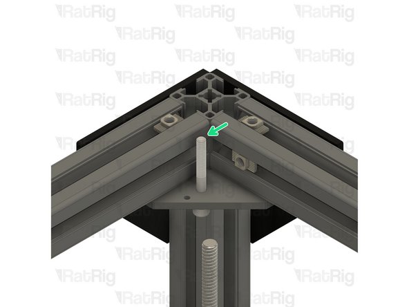
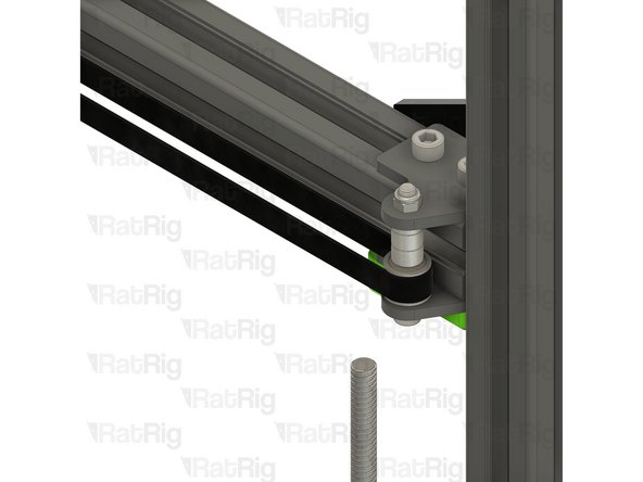
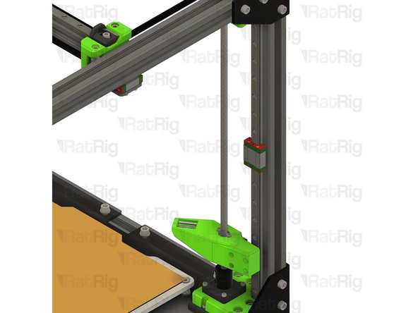
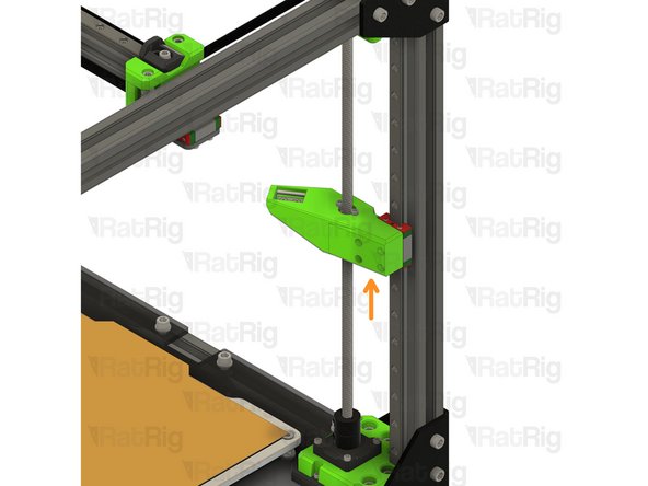
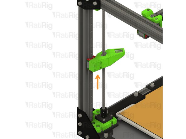
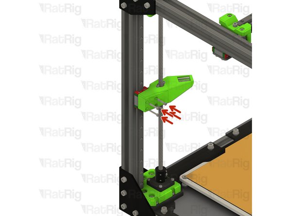
Lift the leadscrew constraint upwards
-
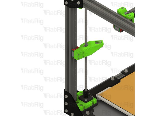
Remove the leadscrew constraint and set it aside until Step 69
-
-
-
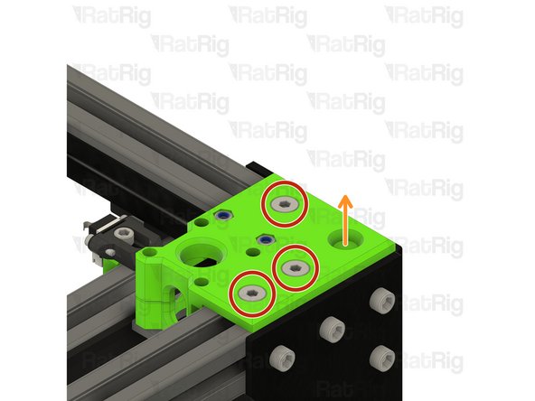
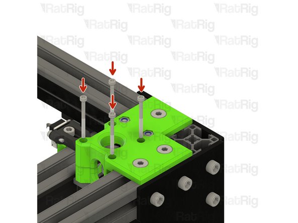
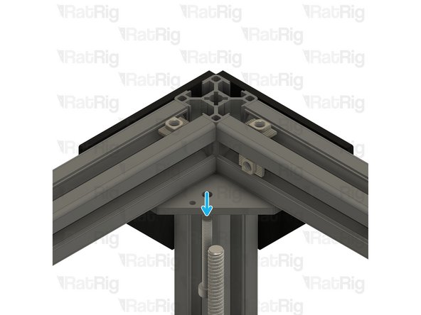
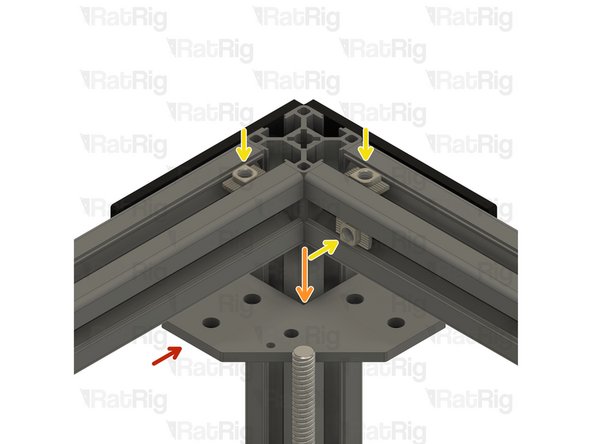
M3x20 Cap Head Screw
-
Remove the four marked M3x20 screws, set them aside until Step 65
-
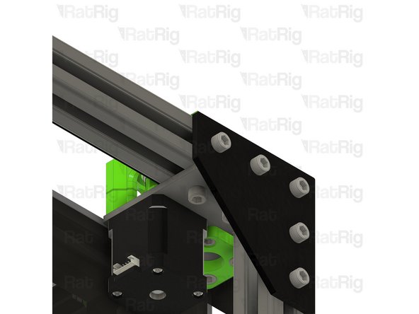
Rotate the leadscrew counter-clockwise to lower the arm to the bottom and rotate the arm as shown
-
-
-
Front left linear rail
-
Loosen but do not remove all of the M3x12 screws securing the linear rail to the frame
-
Pull the linear rail from the frame, taking care not to let the carriage leave the rail
-
Set the linear rail aside until Step 63
-
-
-
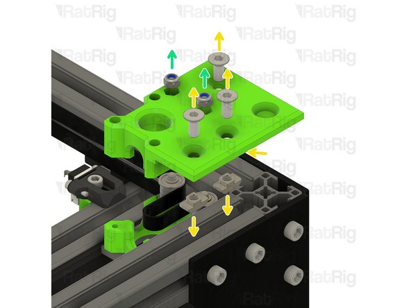
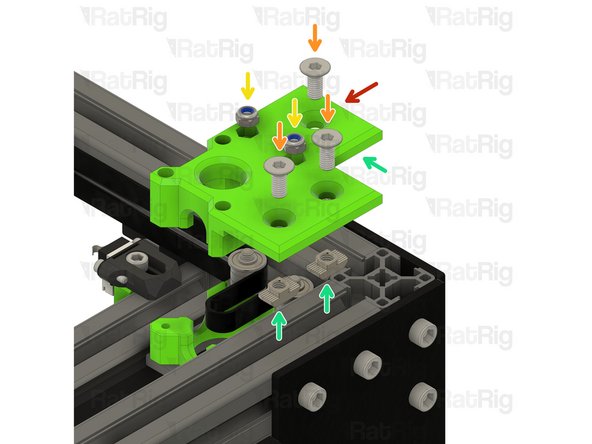
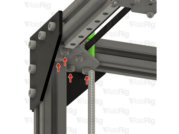
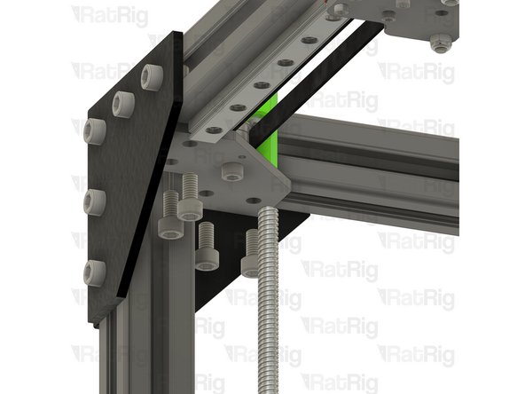
M6x12 Cap Head Screw
-
Remove the marked M6x12 screws
-
-
-
M6x12 Cap Head Screw
-
Remove the marked M6x12 screw
-
This M6x12 screw may be difficult to remove from the printed part. If you are unable to remove it completely, do not worry, you can remove it once the printed part is separated from the frame
-
M6x14 Countersink Screw
-
Remove both marked M6x14 screws
-
-
-
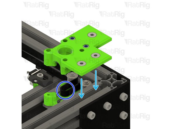
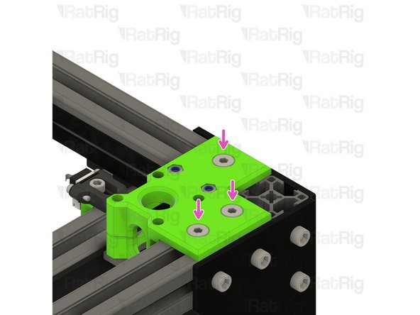
M5x40 Cap Head Screw
-
Loosen, but do not remove, the M5x40 screw. Continue holding it in position with one hand
-
Remove the CoreXY idler printed part
-
-
-
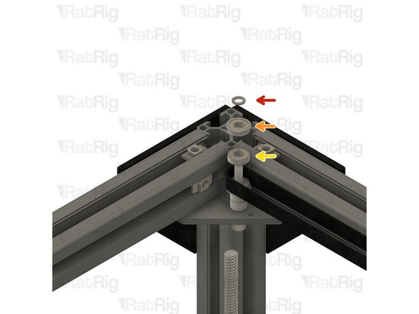
Remove the following components and set them aside until Step 58
-
Mini Precision Shim
-
F695ZZ Ball Bearing
-
695ZZ Ball Bearing
-
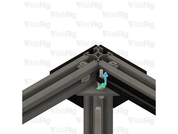
Upper CoreXY belt
-
Lift the CoreXY belt up and over the M5x40 screw, allow it to hang downwards on its own
-
-
-
Remove the following components and set them aside until Step 58
-
F695ZZ Ball Bearing
-
Mini Precision Shim
-
6mm Aluminium Spacer
-
M5x40 Cap Head Screw
-
Remove the M5x40 screw
-
-
-
idler_plate
-
Remove the idler_plate from the frame
-
Some, or all, of the 3030 drop-in t-nuts may fall out of the 3030 extrusion when removing the idler_plate, just set them aside
-
3030 Drop-in T-Nut - M6
-
Remove the three drop-in t-nuts in the top 3030 extrusion
-
Remove the four drop-in t-nuts in the underside of the top 3030 extrusion
-
-
-
M6x12 Cap Head Screw
-
Loosen, but do not remove the two marked M6x12 screws
-
Lift the leadscrew constraint upwards
-
Remove the leadscrew constraint and set it aside until Step 70
-
-
-
M3x20 Cap Head Screw
-
Remove the four marked M3x20 screws, set them aside until Step 68
-
Rotate the leadscrew counter-clockwise to lower the arm to the bottom and rotate the arm as shown
-
-
-
Front right linear rail
-
Loosen but do not remove all of the M3x12 screws securing the linear rail to the frame
-
Pull the linear rail from the frame, taking care not to let the carriage leave the rail
-
Set the linear rail aside until Step 66
-
-
-
M6x12 Cap Head Screw
-
Remove the marked M6x12 screws
-
-
-
M6x12 Cap Head Screw
-
Remove the marked M6x12 screw
-
This M6x12 screw may be difficult to remove from the printed part. If you are unable to remove it completely, do not worry, you can remove it once the printed part is separated from the frame
-
M6x14 Countersink Screw
-
Remove both marked M6x14 screws
-
-
-
M5x40 Cap Head Screw
-
Loosen, but do not remove, the M5x40 screw. Continue holding it in position with one hand
-
Remove the CoreXY idler printed part
-
-
-
Remove the following components and set them aside until Step 60
-
Mini Precision Shim
-
6mm Aluminium Spacer
-
F695ZZ Ball Bearing
-
Upper CoreXY belt
-
Lift the CoreXY belt up and over the M5x40 screw, allow it to hang downwards on its own
-
-
-
Remove the following components and set them aside until Step 60
-
695ZZ Ball Bearing
-
F695ZZ Ball Bearing
-
Mini Precision Shim
-
M5x40 Cap Head Screw
-
Remove the M5x40 screw
-
-
-
idler_plate
-
Remove the idler_plate from the frame
-
Some, or all, of the 3030 drop-in t-nuts may fall out of the 3030 extrusion when removing the idler_plate, just set them aside
-
3030 Drop-in T-Nut - M6
-
Remove the three drop-in t-nuts in the top 3030 extrusion
-
Remove the four drop-in t-nuts in the underside of the top 3030 extrusion
-
-
-
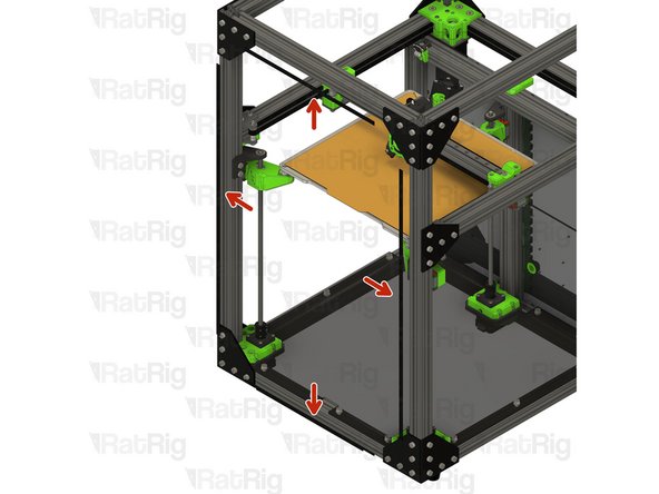
M6x12 Cap Head Screw
-
Loosen all of the marked M6x12 screws and remove the left corner plate assembly
-
Do not remove this corner plate
-
Loosen all of the marked M6x12 screws and remove the right corner plate assembly
-
-
-
Loosen but do not remove the marked M6x12 screws
-
Front 3030 extrusion assembly
-
Remove the extrusion assembly by raising it upwards and off of the frame
-
Set this assembly aside until Step 71
-
-
-
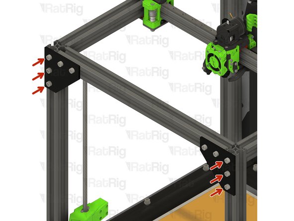
Loosen but do not remove the twelve marked M6x12 screws
-
Three screws on the left side are not visible
-
Front 3030 vertical extrusions
-
Pull the front vertical 3030 extrusion upwards to remove them from the machine frame
-
-
-
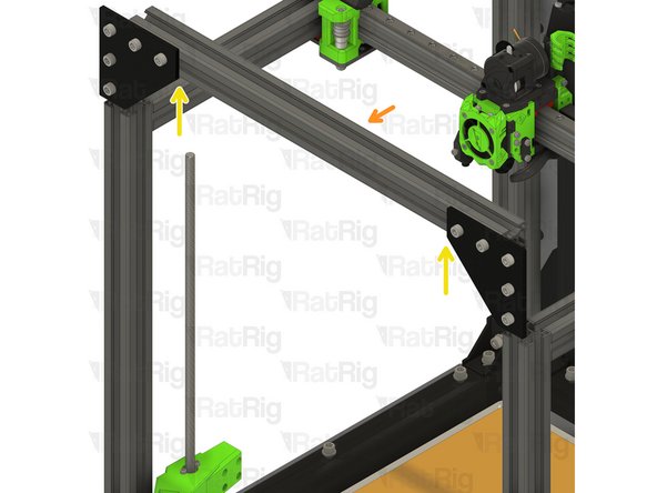
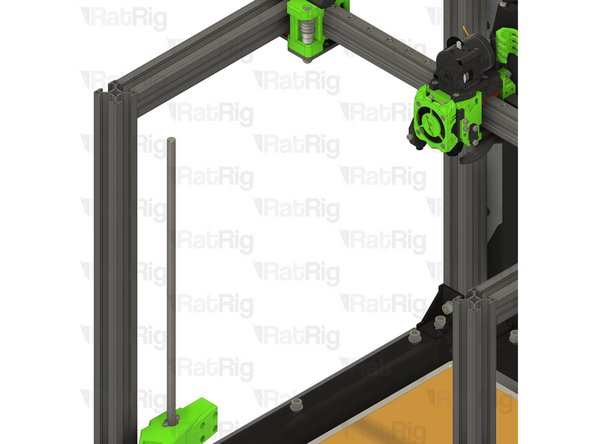
760mm 3030 Extrusion
-
Insert the 3030 extrusions into the bottom corner plate assemblies
-
You may need to rotate the 3030 t-nuts to insert the 3030 extrusion
-
Measure from the underside of the side extrusions, to the top of the newly installed extrusion. It should measure either 230mm (for a V-Core 3 200) or 280mm (for a V-Core 300, 400 or 500)
-
Ensure the extrusions are fully inserted before continuting
-
Tighten the twelve marked M6x12 screws to secure the 3030 extrusions to the frame
-
Three screws on the left side are not visible
-
-
-
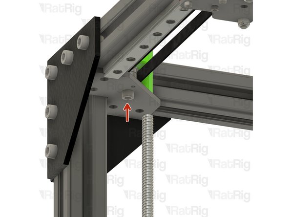
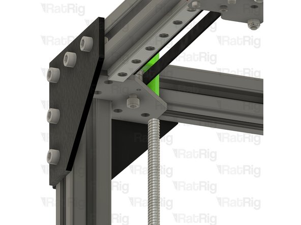
T-Shape plate assembly from Step 2
-
Position the T-shape plate as shown
-
Secure the T-shape plates to the frame by fastening the five M6x12 screws
-
-
-
T-Shape plate assembly from Step 2
-
Position the T-shape plate as shown
-
Secure the T-shape plates to the frame by fastening the five M6x12 screws
-
-
-
8x M6x12 Cap Head Screw
-
8x 3030 Drop-in T-Nut - M6
-
2x M5x45 Cap Head Screw
-
2x 3mm Aluminium Spacer
-
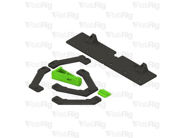
4x idler_plate_enclosure_2.0 plate
-
2x y_min_bumper printed part
-
2x M5 Nylon Locking Hex Nut
-
-
-
M6x12 Cap Head Screw
-
y_min_bumper printed part
-
idler_plate_enclosure_2.0 plate
-
3030 Drop-in T-Nut - M6
-
Loosely thread a 3030 T-Nut onto each of the M6x12 screws. Do not tighten them at this point
-
Pay attention to the different orientation of the idler plates
-
Set these assemblies aside until Steps 57 & 60
-
-
-
M6x12 Cap Head Screw
-
idler_plate_enclosure_2.0 plate
-
3030 Drop-in T-Nut - M6
-
Loosely thread a 3030 T-Nut onto each of the M6x12 screws. Do not tighten them at this point
-
Pay attention to the different orientation of the idler plates
-
Set these assemblies aside until Steps 59 & 62
-
-
-
CoreXY idler assembly from Step 55
-
Position the CoreXY idler assembly onto the V-Core 3 frame as shown
-
Tighten the two M6x12 screws to secure the CoreXY idler assembly to the V-Core 3 frame
-
Make sure the assembly is seated against the front 3030 extrusion before tightening the M6x12 screws
-
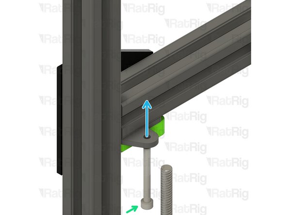
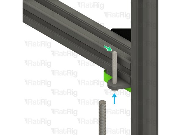
M5x45 Cap Head Screw
-
Insert the M5x45 screw into the CoreXY idler plate as shown, in preparation for the next step
-
-
-
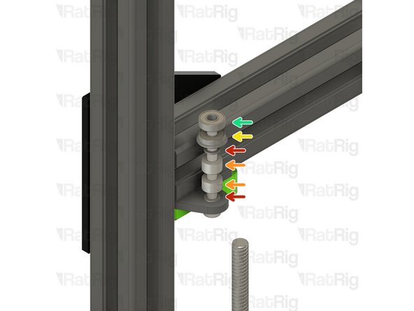
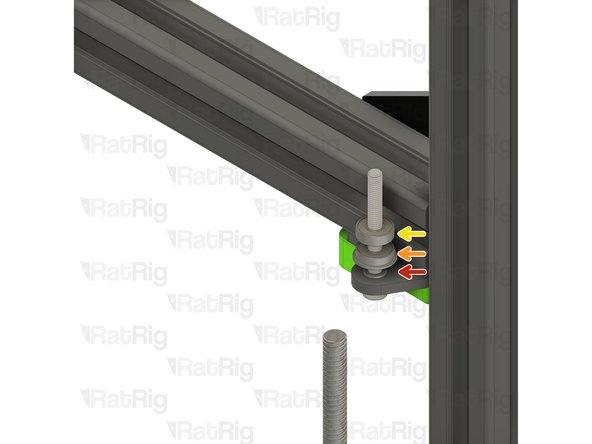
Install the following components from Steps 36 & 37, onto the M5x45 screw in the order shown in the image
-
Mini Precision Shim
-
6mm Aluminium Spacer
-
F695ZZ Ball Bearing
-
695ZZ Ball Bearing
-
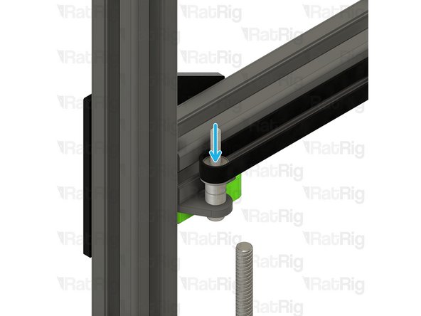
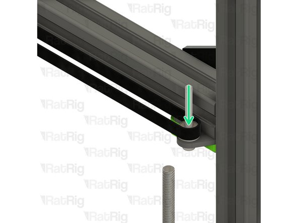
Lift the CoreXY belt up and over the M5x45 screw, positioning it on the bearing stack as shown
-
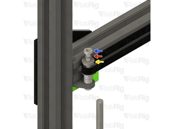
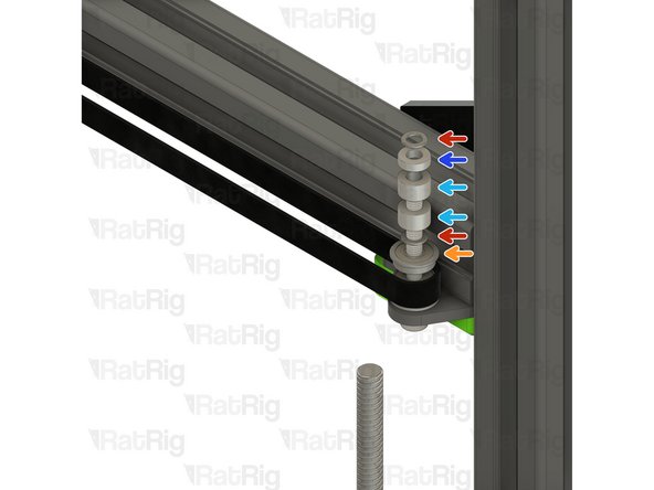
Add the remaining components of the bearing stack
-
3mm Aluminium Spacer
-
-
-
Upper CoreXY idler assembly from Step 56
-
Position the upper CoreXY idler assembly onto the V-Core 3 frame as shown
-
Tighten the two M6x12 screws to secure the upper CoreXY idler assembly to the V-Core 3 frame
-
Make sure the assembly is seated against the front 3030 extrusion before tightening the M6x12 screws
-
M6 Nylon Locking Hex Nut
-
Fasten the M6 hex nut onto the M5x45 screw to secure the bearing assembly in place
-
-
-
CoreXY idler assembly from Step 55
-
Position the CoreXY idler assembly onto the V-Core 3 frame as shown
-
Tighten the two M6x12 screws to secure the CoreXY idler assembly to the V-Core 3 frame
-
Make sure the assembly is seated against the front 3030 extrusion before tightening the M6x12 screws
-
M5x45 Cap Head Screw
-
Insert the M5x45 screw into the CoreXY idler plate as shown, in preparation for the next step
-
-
-
Install the following components from Steps 45 & 46, onto the M5x45 screw in the order shown in the image
-
Mini Precision Shim
-
F695ZZ Ball Bearing
-
695ZZ Ball Bearing
-
Lift the CoreXY belt up and over the M5x45 screw, positioning it on the bearing stack as shown
-
Add the remaining components of the bearing stack
-
6mm Aluminium Spacer
-
3mm Aluminium Spacer
-
-
-
Upper CoreXY idler assembly from Step 56
-
Position the upper CoreXY idler assembly onto the V-Core 3 frame as shown
-
Tighten the two M6x12 screws to secure the upper CoreXY idler assembly to the V-Core 3 frame
-
Make sure the assembly is seated against the front 3030 extrusion before tightening the M6x12 screws
-
M6 Nylon Locking Hex Nut
-
Fasten the M6 hex nut onto the M5x45 screw to secure the bearing assembly in place
-
-
-
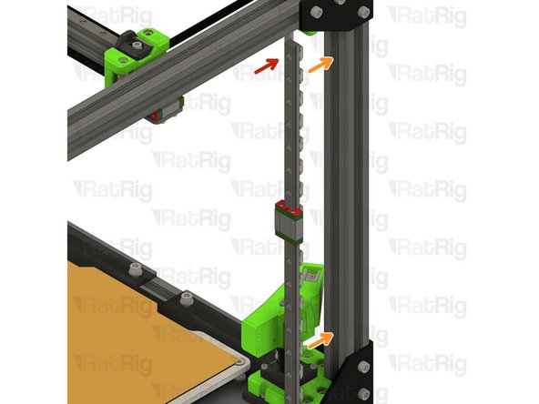
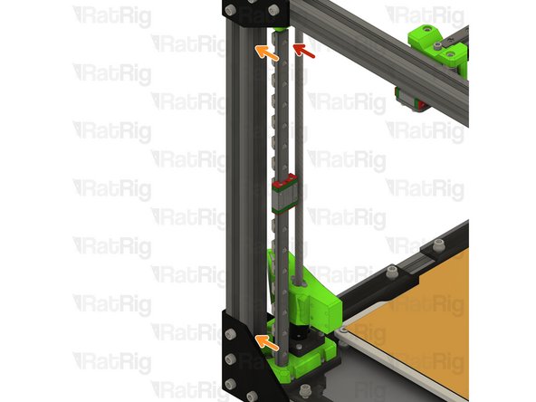
Linear Rail Assembly from Step 32
-
Insert the linear rail into the 3030 extrusion
-
The linear rail will rest on the lead screw motor cage
-
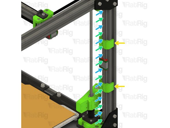
Install the two MGN12 3030 alignment tools as shown, this will make sure the linear rail is positioned correctly
-
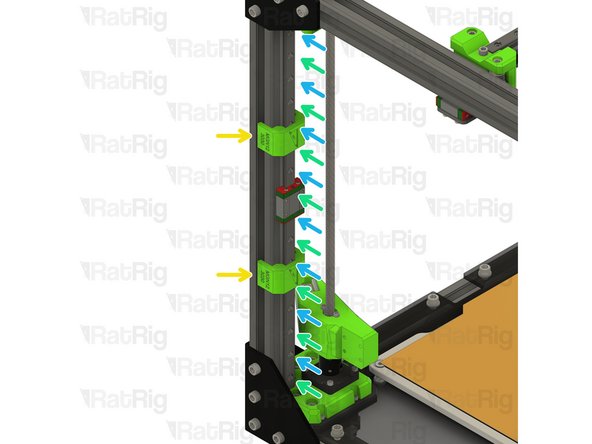
Fasten the marked M3x12 screws, starting from the bottom
-
Fasten the remaining M3x12 screws, starting at the bottom
-
Remove the MGN12 3030 alignment tools
-
-
-
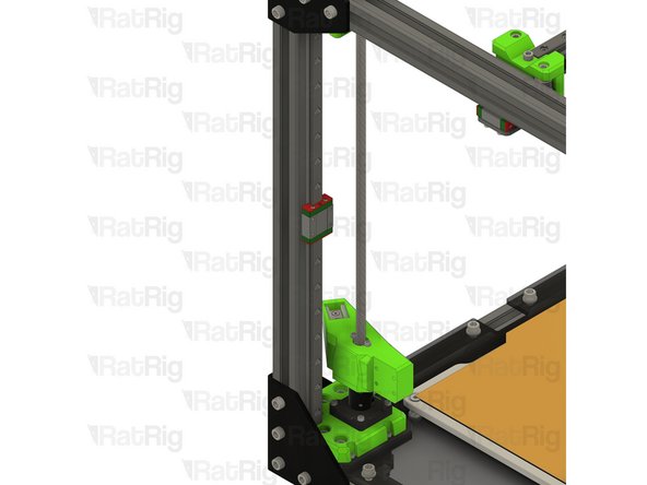
Rotate the bed arm back towards the linear rail
-
Rotate the lead screw clockwise to bring the arm in line with the MGN12 carriage
-
-
-
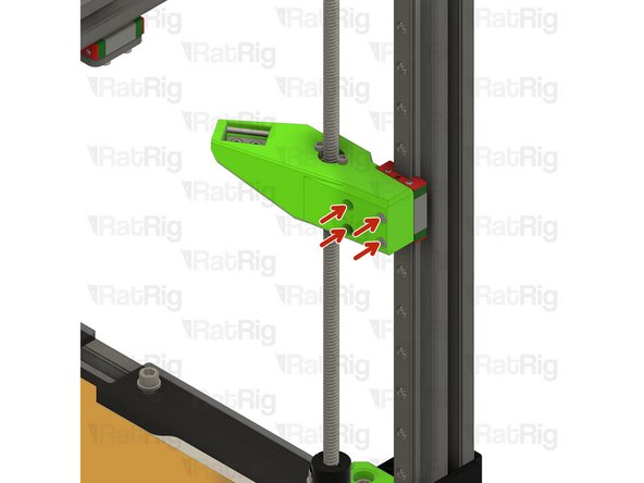
M3x20 Cap Head Screw from Step 31
-
Install each screw through the bed arm assembly as shown, then fasten the arm to the linear rail carriage
-
-
-
Linear Rail Assembly from Step 41
-
Insert the linear rail into the 3030 extrusion
-
The linear rail will rest on the lead screw motor cage
-
Install the two MGN12 3030 alignment tools as shown, this will make sure the linear rail is positioned correctly
-
Fasten the marked M3x12 screws, starting from the bottom
-
Fasten the remaining M3x12 screws, starting at the bottom
-
Remove the MGN12 3030 alignment tools
-
-
-
Rotate the bed arm back towards the linear rail
-
Rotate the lead screw clockwise to bring the arm in line with the MGN12 carriage
-
-
-
M3x20 Cap Head Screw from Step 40
-
Install each screw through the bed arm assembly as shown, then fasten the arm to the linear rail carriage
-
-
-
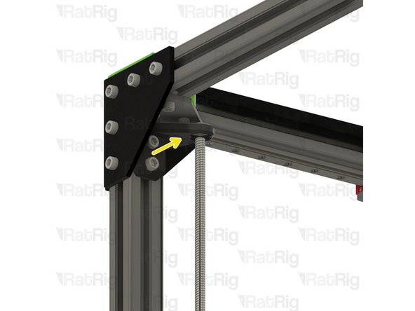
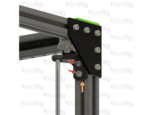
Left leadscrew constraint assembly from Step 30
-
Fit the constraint assembly to the frame as shown
-
Push the constraint assembly downwards until the leadscrew is flush with the top of the bearing
-
Fasten both M6x12 screws to secure the constraint assembly to the V-Core 3 frame
-
-
-
Right leadscrew constraint assembly from Step 39
-
Fit the constraint assembly to the frame as shown
-
Push the constraint assembly downwards until the leadscrew is flush with the top of the bearing
-
Fasten both M6x12 screws to secure the constraint assembly to the V-Core 3 frame
-
-
-
Front 3030 extrusion assembly from Step 49
-
Position the extrusion assembly as shown, the extrusion should be flush with the tops of the Z-axis extrusions
-
Fasten the six M6x12 screws to secure the extrusion to the frame
-
-
-
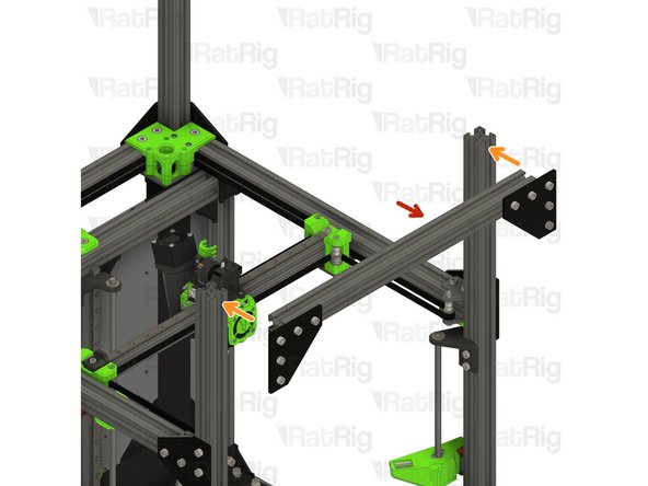
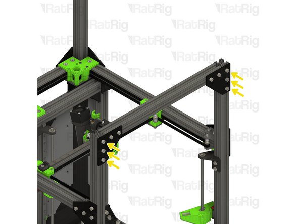
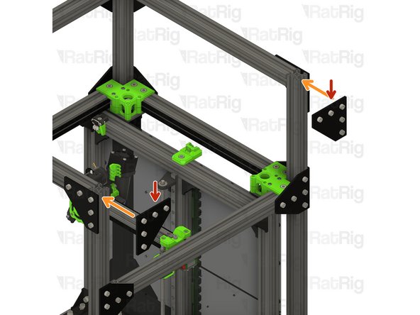
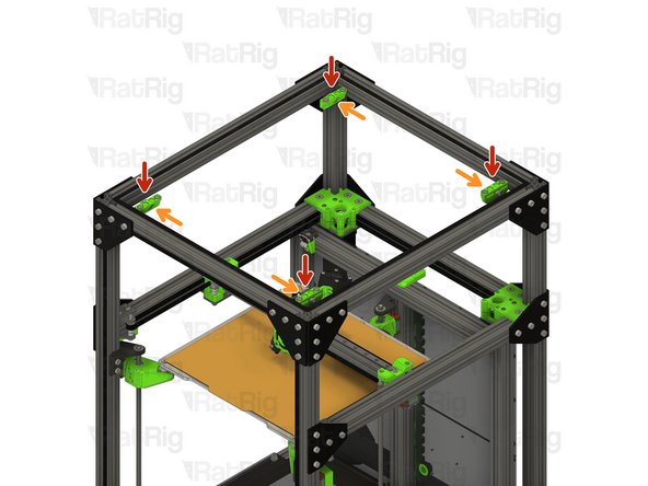
Corner plate assembly from Step 23 & 27
-
Position the corner plate assemblies on the 3030 extrusion ends as shown
-
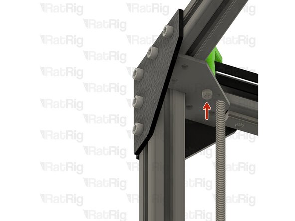
Secure the corner plates to the extrusions by fastening the marked M6x12 screws
-
Check that the corner plates are square to the extrusion, and flush with the ends
-
505mm 3030 Extrusion
-
Fit the 3030 extrusion to the corner plate assemblies as shown
-
Tigthen the marked M6x12 screws to secure the extrusion to the frame
-
-
-
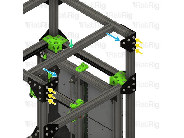
Corner plate assembly from Step 23 & 27
-
Position the corner plate assemblies on the 3030 extrusion ends as shown
-
Secure the corner plates to the extrusions by fastening the marked M6x12 screws
-
Check that the corner plates are square to the extrusion, and flush with the ends
-
440mm 3030 Extrusion
-
Fit the 3030 extrusion to the corner plate assemblies as shown
-
Tigthen the marked M6x12 screws to secure the extrusion to the frame
-
-
-
Corner plate assembly from Step 23 & 27
-
Position the corner plate assemblies on the 3030 extrusion ends as shown
-
Secure the corner plates to the extrusions by fastening the marked M6x12 screws
-
Check that the corner plates are square to the extrusion, and flush with the ends
-
505mm 3030 Extrusion
-
Fit the 3030 extrusion to the corner plate assemblies as shown
-
Tigthen the marked M6x12 screws to secure the extrusion to the frame
-
-
-
The M5x40mm on the EVA3 back screws are used to tighten the CoreXY belts
-
Tighten each M5x40 screw slightly to engage with the M5 nylon locking nut in the tensioner
-
Tighten each M5x40 screw one-half turn at a time to tension the belts equally
-
Continue tightening the screws until the belts are no longer slack
-
Check that the X-axis gantry is square by moving it to the front of the machine. If it has skewed, it can be squared by adjusting the tension of one belt at a time
-
Make sure not to over-tension the belts as this can cause damage to the bearings, the belt, the motors or printed parts!
-
An excellent article on correct CoreXY belt tensioning is available on Mark Rehorst's website
-
-
-
Lift the print bed assembly off of the base panel (or work surface)
-
Set the print bed on the printer arms
-
-
-
2x 3030_panel_mount_horizontal printed part
-
2x M6x12 Cap Head Screw
-
2x 3030 Drop-in T-Nut - M6
-
10x Frame magnet mount assembly from Step 4
-
1x Adhesive backed foam sealing tape
-
-
-
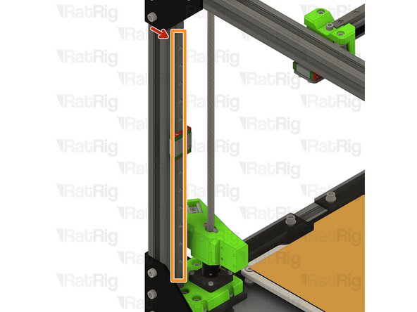
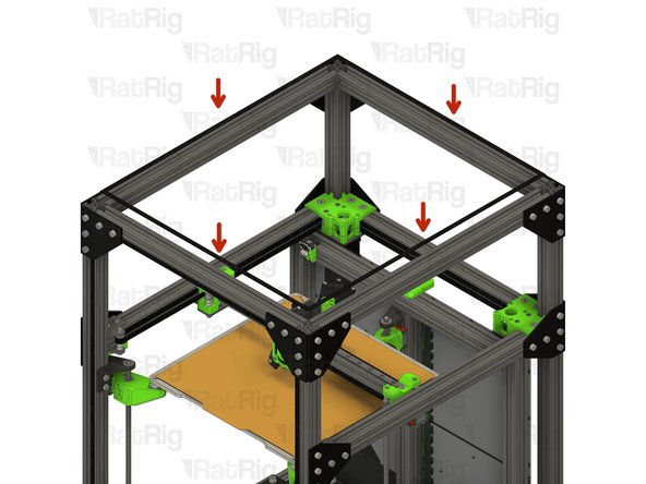
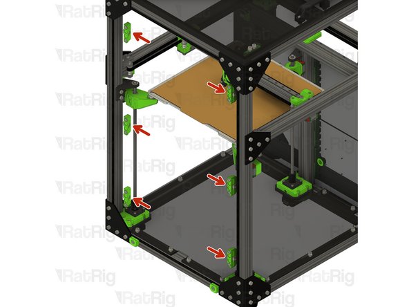
Adhesive foam tape
-
Cut sections of foam tape to fit in the sections shown
-
The foam seal tape is provided with an adhesive backing, peel the backing off and apply it to the frame as shown
-
-
-
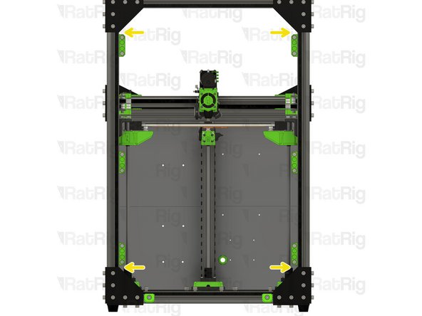
Following the instructions in the previous step, apply the foam tape around the top extrusions as well
-
-
-
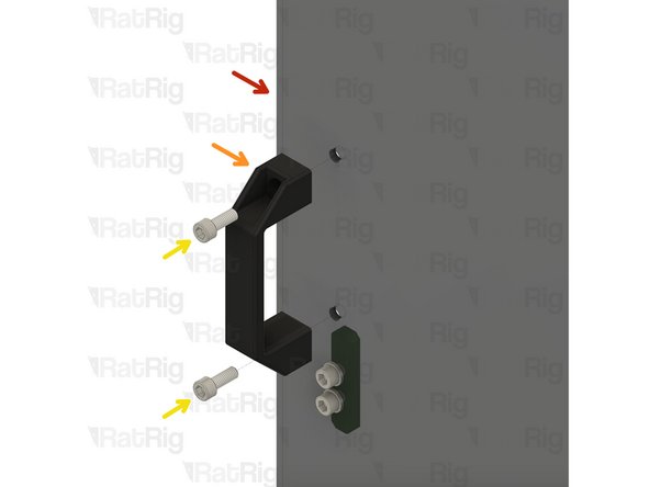
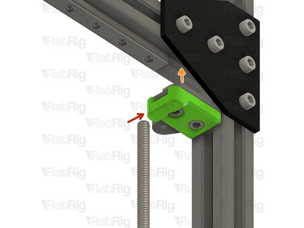
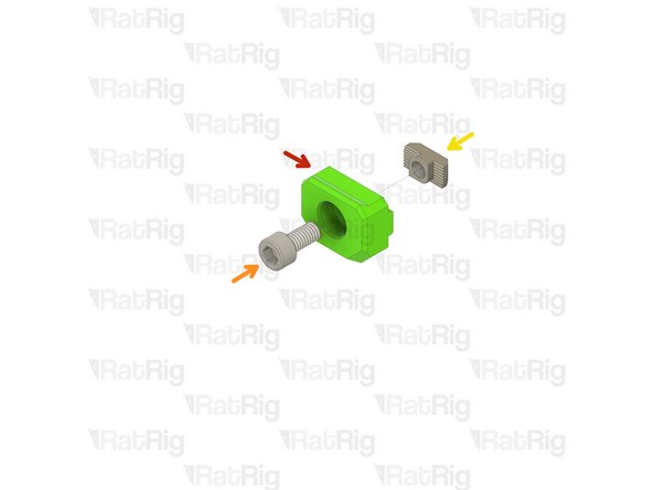
3030_panel_mount_horizontal printed part
-
M6x12 Cap Head Screw
-
3030 Drop-in T-Nut - M6
-
Loosely thread the 3030 T-Nuts onto the M6x12 screws. Do not tighten them at this point.
-
-
-
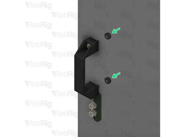
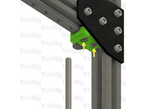
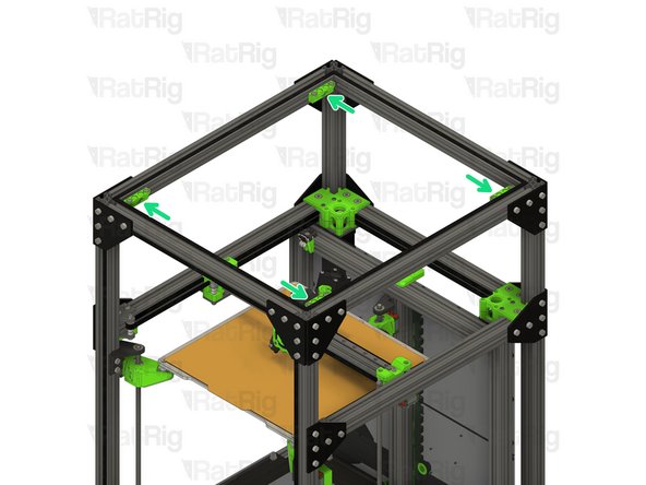
Horizontal 3030 panel holder assembly from Step 80
-
Align the 3030 panel holder assemblies as shown
-
Tighten the M6x12 screws to secure the assemblies to the frame
-
Take care not to over tighten the M6x12 screws as you can damage the printed parts
-
-
-
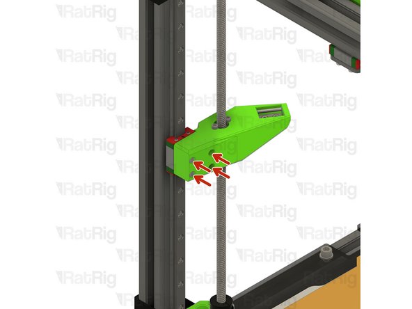
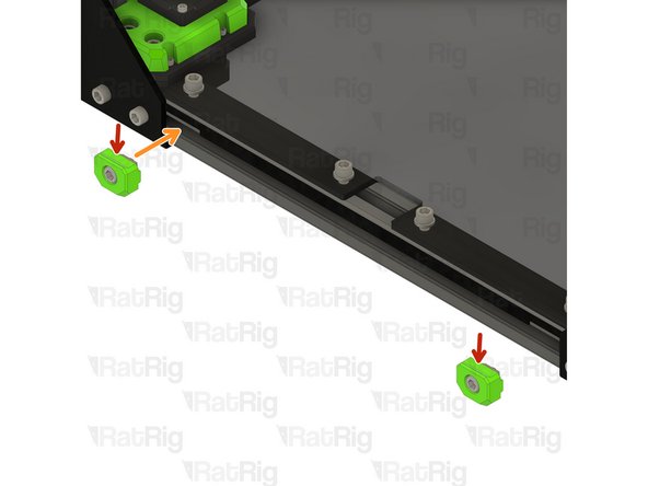
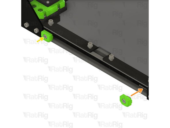
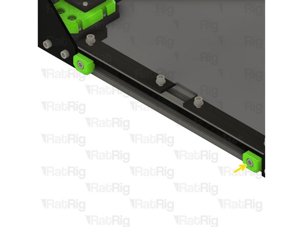
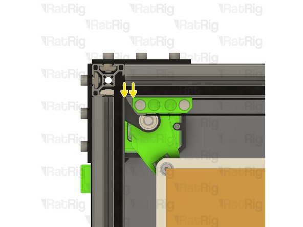
Frame magnet mount assembly from Step 4
-
Position each magnet mount assembly as shown
-
The marked gap should measure 6.50mm
-
Tighten the M6x12 screw to secure each assembly to the frame
-
Take care not to over tighten the M6x12 screws as you can damage the printed parts
-
The exact position of the magnet mounts can be adjusted once the top panel in in place
-
-
-
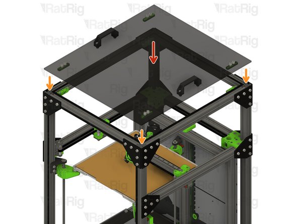
Top panel assembly from Step 11
-
Place the top panel onto the top of the printer
-
The magnets should align the panel automatically. If the alignment needs to be adjusted, alter the position of the magnet holders installed in Step 82
-
-
-
Frame magnet mount assembly from Step 4
-
Position each magnet mount assembly as shown
-
The marked gaps should measure 5mm
-
It is easiest to align the central magnet mounts once the door panel is in place, position them roughly in the middle for now
-
Tighten the M6x12 screw to secure each assembly to the frame
-
Take care not to over tighten the M6x12 screws as you can damage the printed parts
-
The exact position of the magnet mounts can be adjusted once the door is in place
-
-
-
Door panel assembly from Step 10
-
Rest the door panel on the horizontal 3030 panel mounts, then rotate towards the printer to secure it
-
The magnets should align the panel automatically. If the alignment needs to be adjusted, alter the position of the magnet holders installed in Step 84
-
-
-
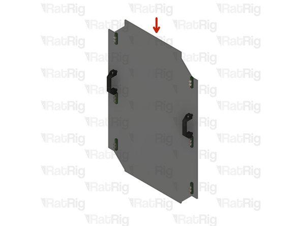
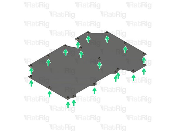
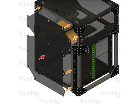
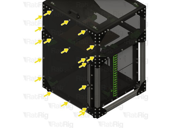
Rear enclosure panel from Step 14
-
Align the panel to the frame as shown
-
Secure the panel in place by fastening the ten M6x12 screws
-
-
-
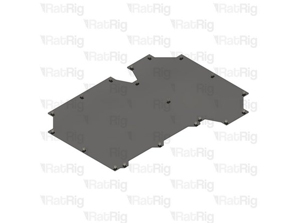
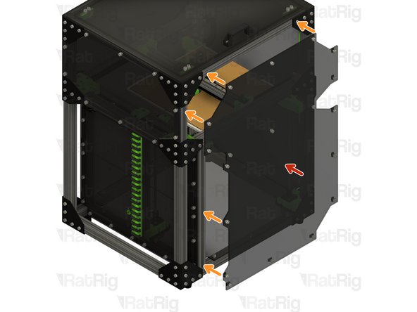
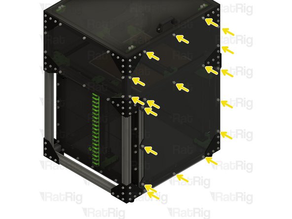
Right enclosure panel from Step 14
-
Align the panel to the frame as shown
-
Secure the panel in place by fastening the nineteen M6x12 screws
-
-
-
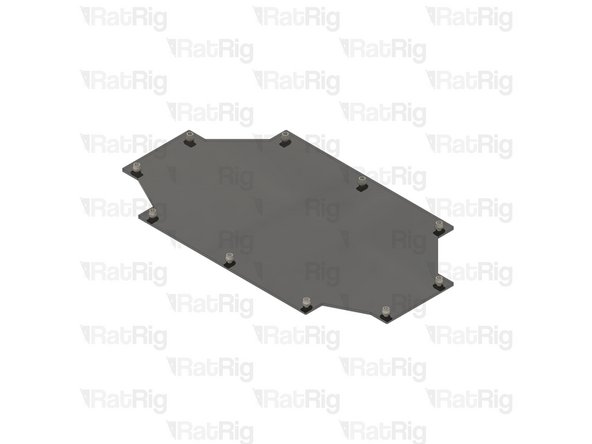
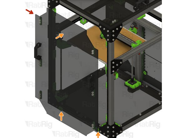
Left enclosure panel from Step 14
-
Align the panel to the frame as shown
-
Secure the panel in place by fastening the nineteen M6x12 screws
-
-
-
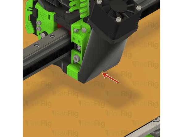
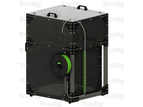
It is recommended to use a length of PTFE tube to route the filament into the enclosure as shown
-
-
-
Rat Rig has developed, and provide, a set of optional extra printed parts for the V-Core 3 Enclosure 2.0
-
Parts available include:
-
Panel trims for the exterior of the enclosure
-
A brand-new, side-mounted, printable spool holder
-
A rear shelf, designed to sit above the electronics and help fully enclose the print volume
-
Other miscellaneous parts
-
Parts can be found on the V-Core 3 project pages and the Rat Rig Lab site
-


Cancel: I did not complete this guide.
2 other people completed this guide.