
Video Overview
-
-
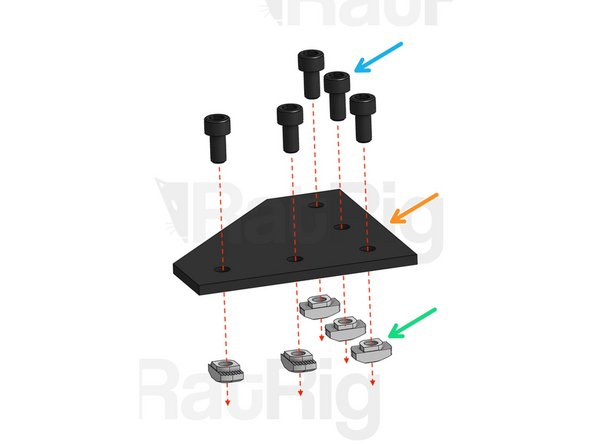
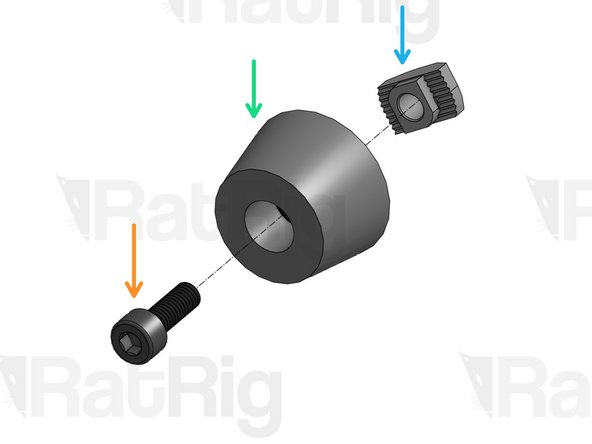
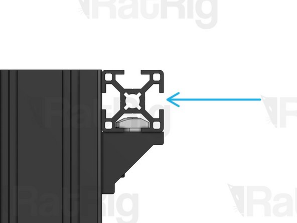
These are Drop-in T-Nuts. In this build we use 2020 and 3030 Drop-in T-Nuts. They fit inside the slots of the V-Slot 2020 and the T-Slot 3030 Aluminum profiles (respectively).
-
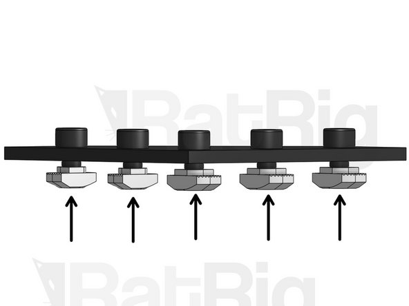
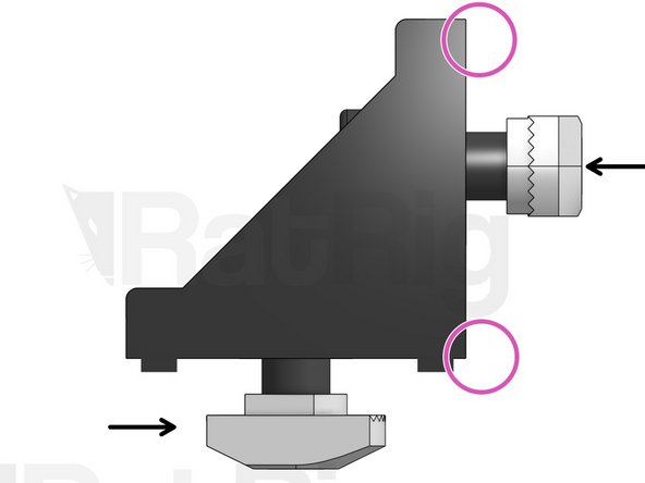
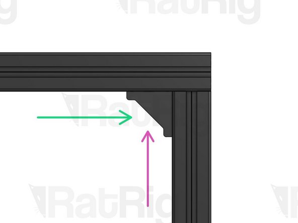
When a bolt is screwed through a plate/connector and into a Drop-in T-Nut, the Nut rotates inside the slot and rises, until it eventually grabs the inside of the profile, in a position perpendicular to the slot. In this position, the bolt is securely tightened.
-
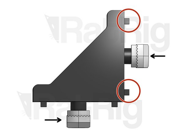
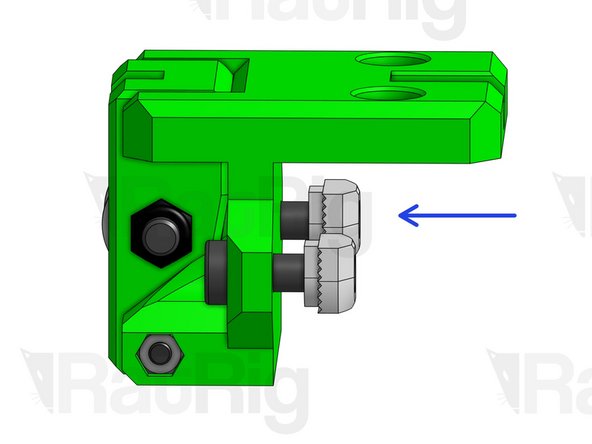
This picture shows an insecurely tightened bolt. As you can see, the Drop-in T-Nut is fully fastened but in a position that is NOT perpendicular to the slot. If this happens, loosen the bolt and re-tighten.
-
To make the assembly process easier, this guide will often ask you to mount Drop-in T-Nuts on screws before mounting them on a profile slot. When you do this, ensure you don't over-tighten the screws into the T-Nuts, otherwise they won't have room to rotate inside the slot, creating the problem described above.
-
-
-
Cap Head M6x12mm
-
Joining Plate
-
3030 Drop-in T-Nut M6
-
Screw T-Nuts into position, but don’t tighten.
-
-
-
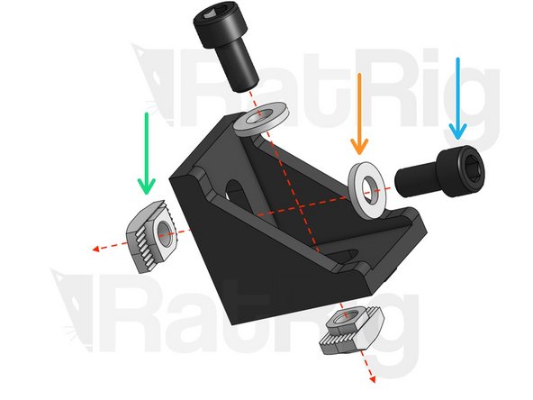
Cap head M6x12mm
-
Washer M6
-
3030 Drop-in T-Nut M6
-
10x 3030 Connector (bigger, tabs on both sides)
-
2x 2030 Connector (smaller, tabs only on one side) Put these aside and save them for last!
-
Screw T-Nuts into position, but don’t tighten.
-
-
-
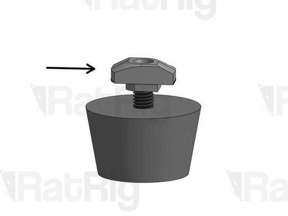
Cap Head Screw M5x14mm
-
Rubber Foot
-
3030 Drop-in T-Nut M5
-
Screw T-Nut into position, but don’t tighten.
-
-
-
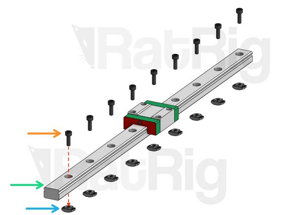
You may want to start by checking out the first 2 steps of our Linear Rail Set Up guide.
-
4x MGN12
-
Cap head M3x12mm
-
3030 Drop-in T-Nut M3
-
1x MGN15
-
Cap head M3x10mm
-
2020 Drop-in T-Nut M3
-
Screw T-nuts into position, but don’t tighten.
-
-
-
Tighten screws only enough for the parts to hold their position. You will need some play on the next steps.
-
3030 T-Slot 492mm
-
3030 T-Slot 480mm
-
Corner Connector 3030
-
Joining Plate
-
-
-
Cast corner screws: fasten them slightly, leaving them loose enough that they can slide through the profile if needed.
-
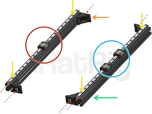
Lightly fasten one screw at both ends of each linear rail. Leave the others loose for now. As a reference, the distance between each linear rail and the profile edge should be 9mm on either side.
-
3030 T-Slot 480mm
-
MGN12 Linear Rail 500mm + 1x MGN12C
-
MGN12 Linear Rail 500mm + 2x MGN12C
-
-
-
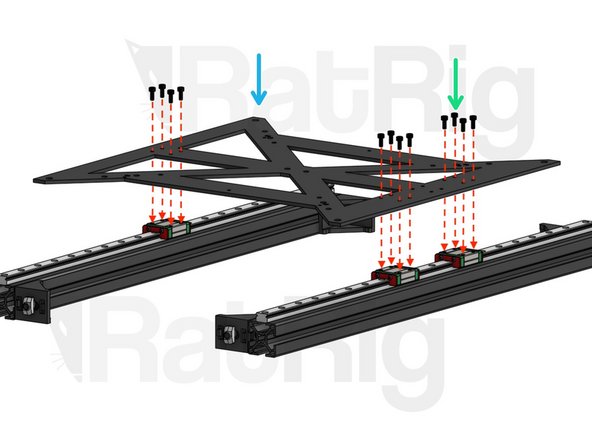
Cap Head M3x8mm. Do not overtighten these screws.
-
Y carriage Plate
-
CAUTION: when you move this block after assembly, be careful not to twist or apply too much load to the Y carriage plate. Remember that the Y carriage is free to move along the linear rails, so hold it tightly.
-
-
-
Place the Y axis assembly into the base of the frame. The tips of the linear rails must rest flat on top of the 492mm profiles, to prevent torsion.
-
61.5 mm (distance between Y rails and base of frame). This distance should be roughly the same on both sides.
-
The next steps are the foundation for the rest of your printer. Read carefully and take your time to get them right.
-
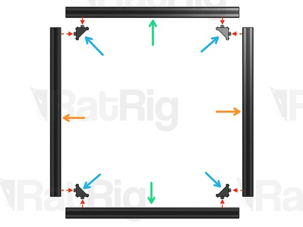
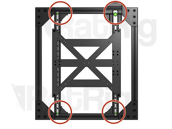
Start by tightening the outer frame. Make sure everything is square and tighten all Corner Connectors first and then all the Joining Plates. Use a squaring tool if you have one.
-
This side first! Whenever a corner connector joins two profiles, you should always fasten this screw first (the one that is closer to the end of the profile). This really helps to ensure squareness.
-
Fasten this screw only after the previous one is fastened.
-
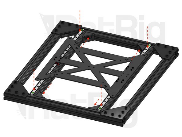
Next, fasten the Corner Connectors on the Y profiles to attach them to the frame. After doing this, you need to ensure that the 2 Y Linear Rails are perfectly parallel. When they are paralell, the Y carriage slides smoothly throughout its entire range of movement.
-
To do this, start by locking the position of one of the Linear Rails, while leaving the other Rail loose enough that it can move. Slide the Y carriage all the way through, back and forth, to establish the correct position, and then fasten all screws on the second Linear Rail. Start by tightening the screws at the tips and work your way inwards.
-
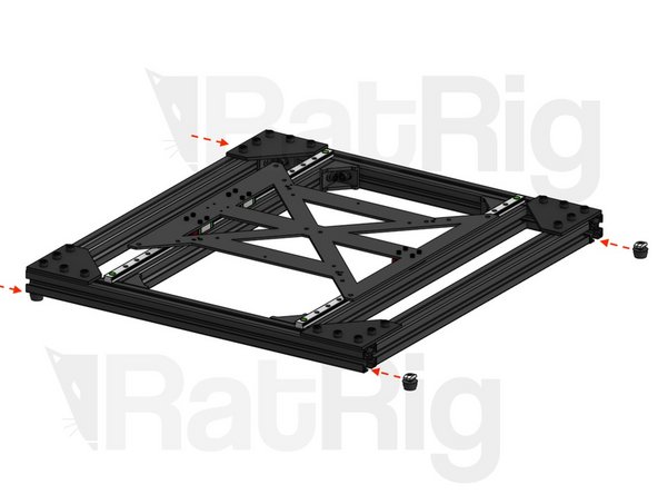
-
-
Insert the feet and screw them in, to lock them into position. Do not over-tighten, to prevent deforming the rubber.
-
Before moving forward, make sure that there aren't any loose screws in the block you just built. Every screw should be properly fastened at this point.
-
-
-
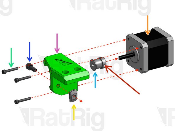
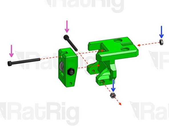
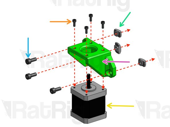
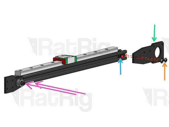
Nema 17 Motor
-
GT2 Pulley 20 Tooth
-
Tighten with 2mm Hex Key. IMPORTANT: the set screw should press against the flat section of the D-shaped motor shaft.
-
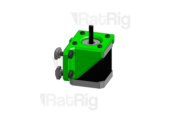
Y Support Nema (Printed Part)
-
Cap Head M3x20mm
-
3030 Drop-in T-Nut M5. Screw into position, but don’t tighten.
-
Cap Head M5x12mm
-
-
-
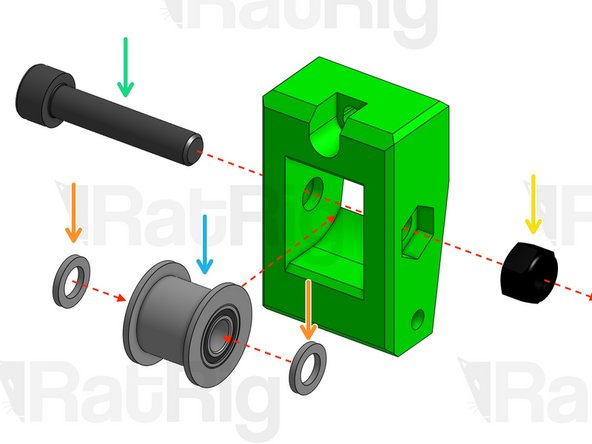
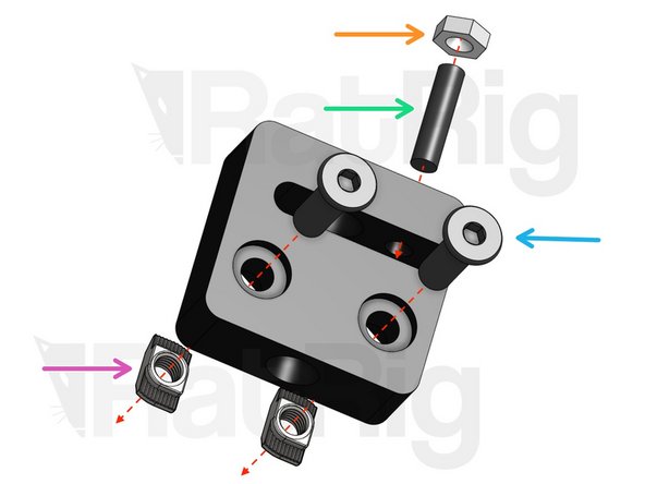
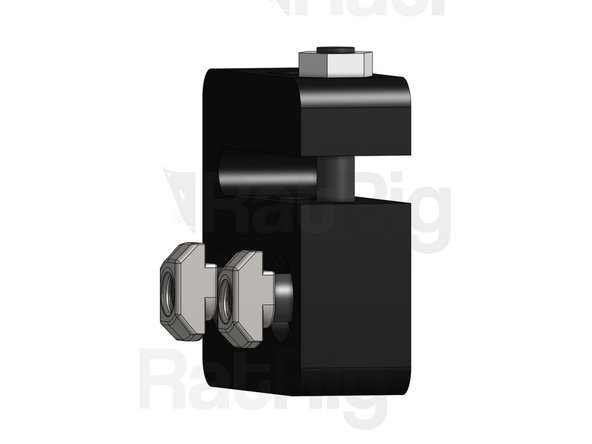
Pulley GT2 for 9mm Belt
-
Mini Precision Shim 8x5x1
-
Cap Head Screw M5*25mm
-
Hex Locking Nut M5. CAUTION: do not over-tighten, leave loose enough for the pulley to spin freely.
-
Cap Head Screw M3*35mm. Do not tighten the top screw, this is your belt tensioner screw. Stop tightening as soon as it passes through the Hex nut.
-
Hex Nut M3
-
-
-
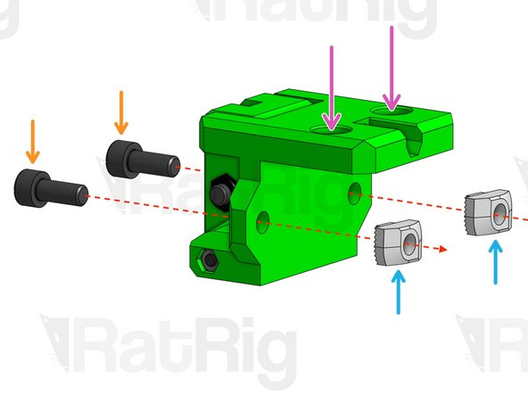
Cap Head Screw M5*12mm
-
Drop-in T-Nut M5 for 3030
-
Poke through the top holes with a screw driver.
-
Screw T-Nuts into position, but don’t tighten.
-
-
-
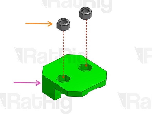
Hex Locking Nut M5
-
Bottom of belt holder. After fitting the nuts, turn it upside down.
-
9mm Belt
-
~470mm
-
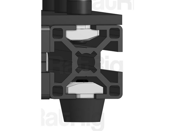
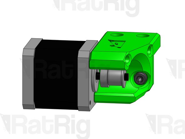
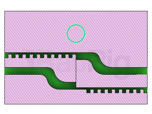
Loop the belt around the pulleys of the motor and tensioner modules and clamp them inside the belt holder, with some left over belt coming out of each side.
-
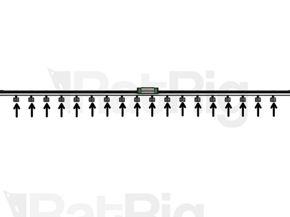
Cross-section of the belt holder. Notice the belt path. the belt's teeth should fit inside the holder's teeth.
-
-
-
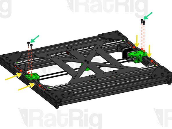
Place the base of the frame on top of the Y Belt Assembly from the previous step.
-
Cap Head M5x30mm. Use them to fasten the belt holder to the Y carriage. Do not tighten too much for now, you want to be able to adjust the belt tension.
-
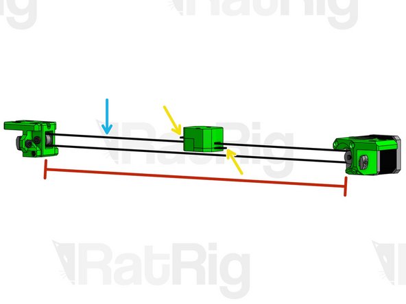
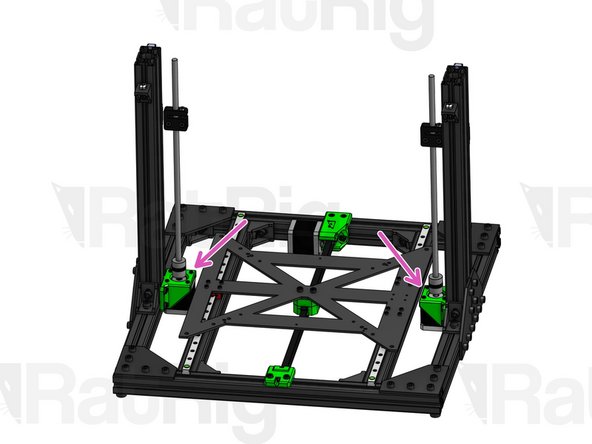
Place the motor and tensioner modules inside the respective profile slots. Adjust their lateral position to make sure the belt is completely straight and screw these modules tightly in place (blue arrows point to the screws you should tighten).
-
113.5mm measured from end of printed part to MGN12 Linear Rail. This part is centered, so the distance is the same on both sides. The "Y Support Nema" is not centered. On this part, distance to the linear rail is: 118mm (motor side) and 111mm (pulley side).
-
3030 Drop-in T-Nut M5. Slide them inside the slot until they are aligned with the holes on the printed parts.
-
Cap Head Screw M5x12mm. Tighten motor and tensioner modules with these screws.
-
-
-
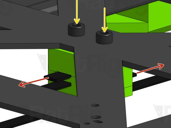
Now that the modules are firmly in place, pull both tips of the belt until you find adequate tension.
-
After finding this position, firmly hold the belt holder with your fingers to clamp the belt and finish tightening the M5x30mm screws.
-
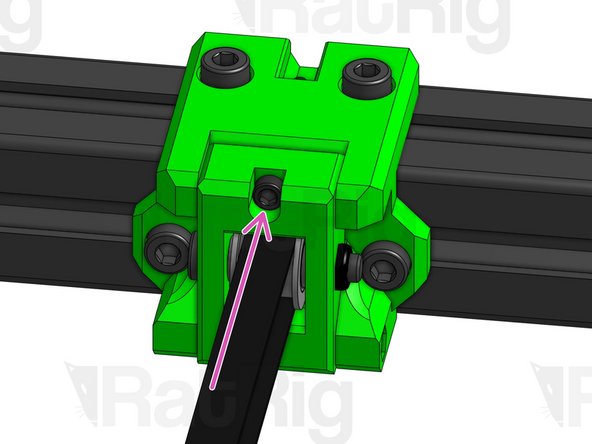
Tension adjusting screw. Tighten or loosen it to finely tune your tension.
-
-
-
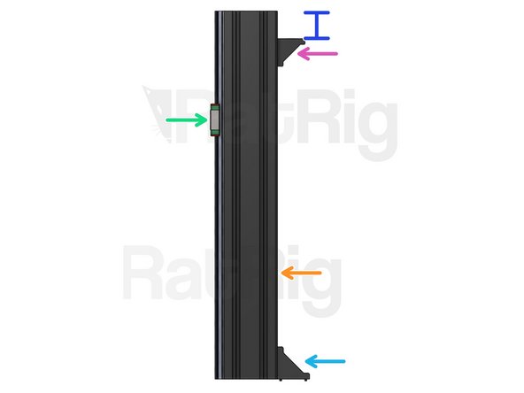
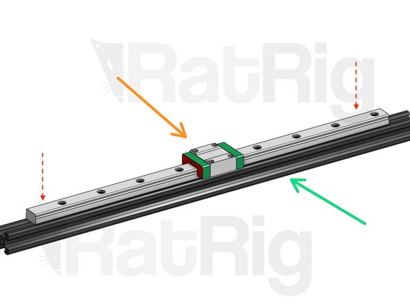
Mount the linear rails on the 3060 Profiles, but only lightly fasten one screw at each extremity. You may need to adjust these later. As a reference, the distance between each linear rail and the profile edge should be 9mm on either side.
-
CAUTION: align the extremity of the Linear Rails with the top side of the profiles, not the bottom side (top and bottom as seen on the picture).
-
3060 T-Slot 400mm
-
MGN12 Linear Rail 400mm
-
Corner Connector 3030
-
Corner Connector 2030 (side with no tabs facing up)
-
This length should be 30mm
-
-
-
Screw T-Nuts into position, but don’t tighten.
-
Set Screw M5x16mm. Fasten all the way till the end and stop as soon as you feel the slightest resistance.
-
Hex Nut M5. Fasten all the way till the end and stop as soon as you feel the slightest resistance.
-
Low Profile Screw 15mm
-
2020 Drop-in T-Nut M5
-
-
-
Cap Head M3x8mm
-
Cap Head M5x12mm
-
Z_Support_Nema (Left/Right) (Printed Part)
-
3030 Drop-in T-Nut M5. Screw into place, but don’t tighten.
-
Nema 17 Motor
-
-
-
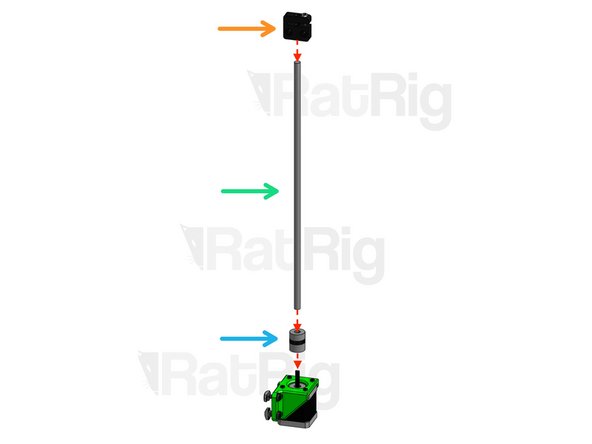
Anti-backlash Nut Block
-
Lead Screw 350mm
-
Flexible Coupling 5x8mm. After assembling, tighten the set screws on the flexible coupling to hold the motor and the lead screw in place. One set screw should center on the flat section of the D-shaped motor shaft. Then tighten the 2 clamping bolts. One will clamp down on the 8mm leadscrew, and the other on the 5mm Motor shaft.
-
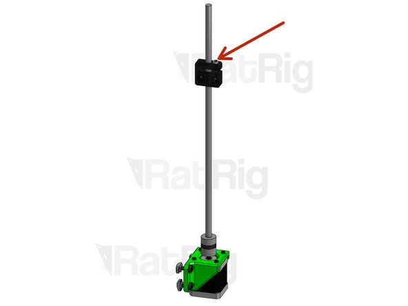
Hold the lead screw with one hand and the Anti-backlash Nut block with the other. Without turning the Nut block, try to move it up and down. If you notice any wiggle room, tighten the Set Screw on the Nut Block until all play disappears. Then, tighten the M4 Hex Nut to lock the Set Screw in place.
-
Do not overtighten the Set Screw, as this may over-constrain the lead screw.
-
-
-
Assemble the Z pillars by tightening the vertical screws on the Corner Connectors first. Don't tighten too hard for now, you may need to adjust.
-
216mm
-
204mm
-
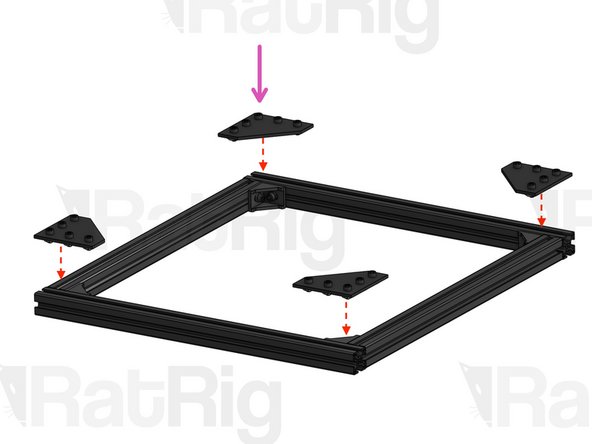
Joining Plates (x4). Use these plates to help you square the Z Pillars. Once you're sure your assembly is square, tightly fasten all screws both on the Joining Plates and on the Cast Corners.
-
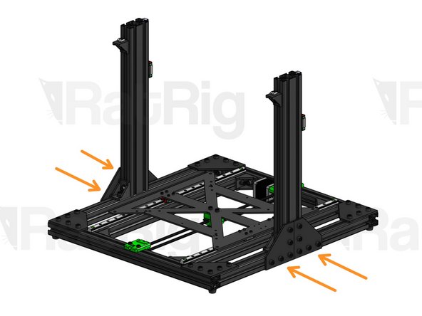
Add the Z motors to the structure and firmly tighten the screws.
-
CAUTION: look carefully at the image to understand which motor mount should go left and which should go right. The positioning is NOT reversible.
-
-
-
SINGLE EXTRUDER: the next steps describe the Single Extruder assembly. For the Dual Extruder assembly, jump to the IDEX instructions.
-
Mount the linear rail on the 360mm profile, making sure it's perfectly centered and aligned. Tighten all screws.
-
MGN15 Linear Rail 360mm + MGN15C
-
2020 V-Slot 420mm
-
-
-
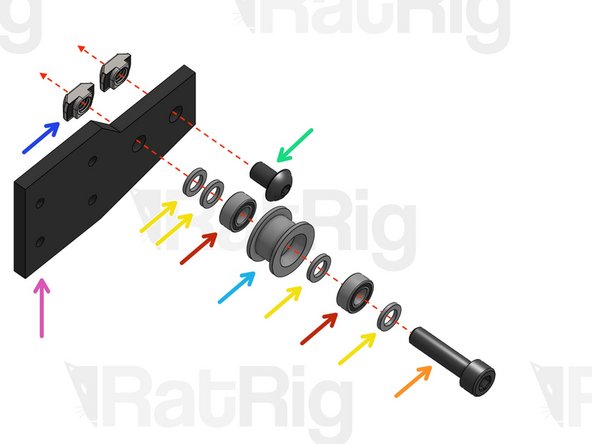
Cap Head M5x20mm
-
Mini Precision Shim 8x5x1
-
Mini Ball Bearing
-
Button Head M5x8mm
-
Idler Pulley GT2 (for 6mm belt)
-
2020 Drop-in T-Nut M5
-
X Axis Idler Plate
-
Screw T-Nuts into place, but don’t tighten.
-
-
-
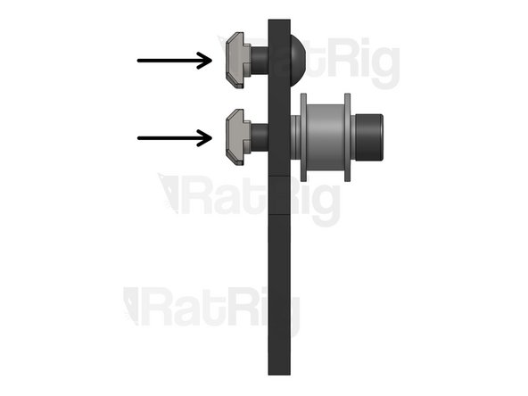
Drop-in T-Nut 2020 M5
-
X Plate Motor
-
Button Head M5x8mm. Do not tighten too much, you will need some play on the next step.
-
Fasten screws to attach plate to rail. Do not tighten too much, you will need some play on the next step.
-
-
-
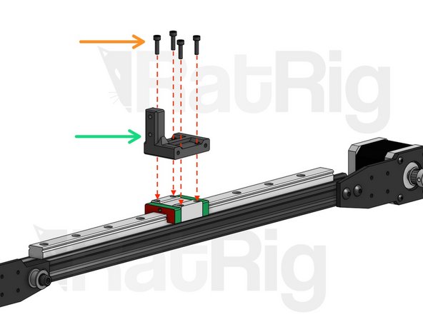
Button Head M3x8mm. Attach the X axis to the linear rail carriages.
-
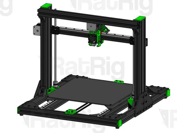
After attaching the X Axis, move it upwards to its top position, making sure it's level, and firmly tighten these 4 screws, making sure the plates don't twist.
-
Slide the X Axis up and down throughout its entire range of movement to ensure that the 2 Z Linear Rails are perfectly parallel. If the carriages bind at any point, you will need to adjust their positioning.
-
To do this, start by tightening the screws on one of the Linear Rails first, while leaving the other Rail loose enough that it can move. Slide the X Axis all the way through, up and down, to establish the correct position, and then tighten the second linear rail. Start by tightening the screws at the tips and work your way inwards.
-
This step is very important to get the best performance. Take your time to get it right.
-
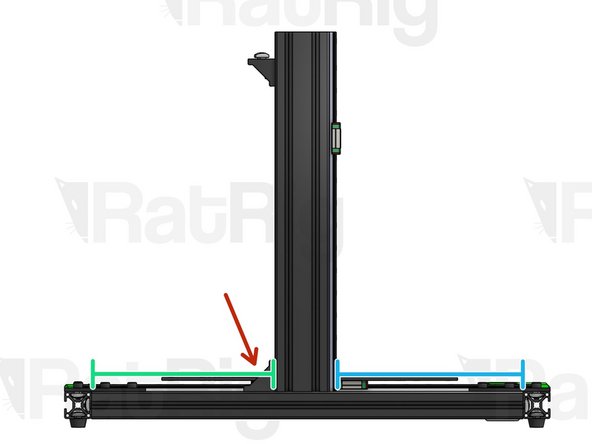
After everything is tight, align the Anti-backlash nuts flush against the tips of the 2020 profile. While positioning the Anti-Backlash nuts, make sure the Lead screws are straight and parallel between themselves as well as the 3060 Z pillars. They should not be tilting away or towards the pillars. Tighten the screws.
-
If later in the build you install the Z Tops (printed parts), you can look directly down through their top hole to make sure the Lead screws are perfectly straight.
-
-
-
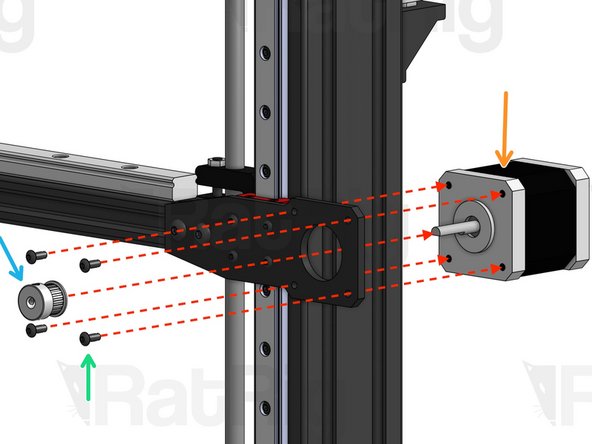
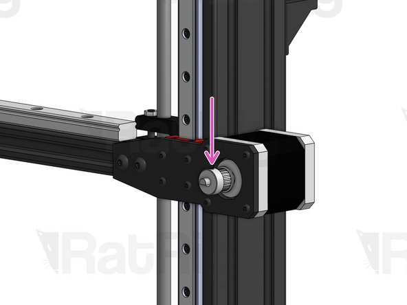
Nema 17 Motor
-
Timing Pulley GT2 20T (for 6mm belt)
-
Button Head M3x8mm
-
Tighten set screw to lock pulley in place. One set screw should center on the flat section of the D-shaped motor shaft.
-
-
-
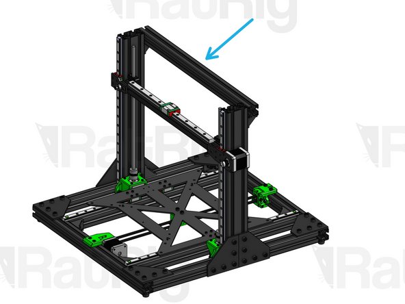
3030 T-Slot 492mm. Hold against the Z pillars and tighten screws on Corner Connectors below.
-
-
-
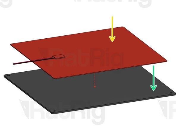
THIS SIDE UP: on the top side of the bedplate you can see 4 counterbore holes to make room for screw heads. On the bottom side, you will only see 4 small holes.
-
Glue your heat pad to the BOTTOM SIDE of the bed plate. Be careful not to place the pad over any of the bedplate holes.
-
Heat pad
-
Bedplate
-
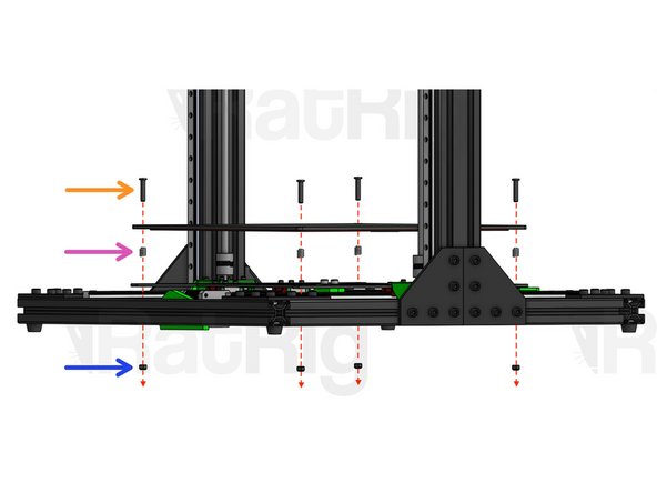
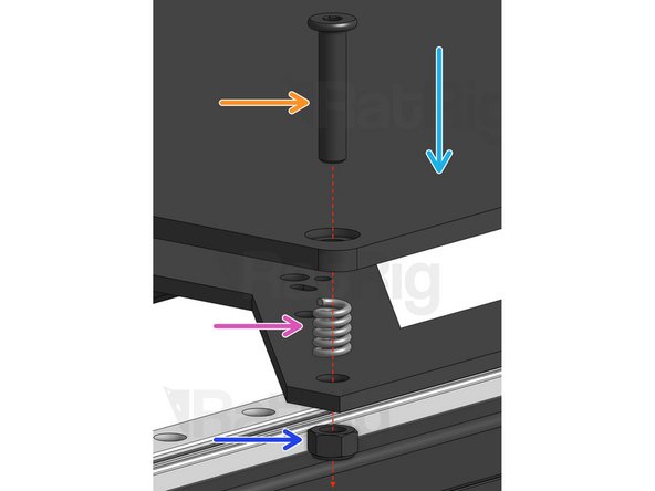
Low profile M5x25mm
-
Spring
-
Hex Locking Nut M5. Tighten or loosen these to level your bed.
-
-
-
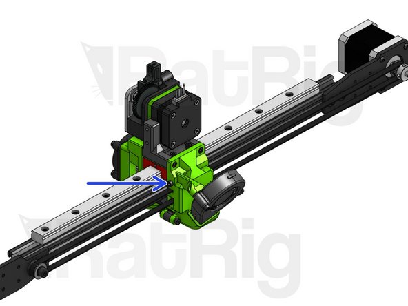
Assemble your EVA carriage(s) on the X Axis Assembly.
-
The specific EVA carriage(s) you will be using depends on the Extruder/Hot-end combination you’ve chosen.
-
You can find instructions on how to assemble your specific EVA carriage(s) here.
-
The EVA carriage represented in the image may look different from yours, but the assembly steps remain the same.
-
When assembling, set your tension adjuster screw to the loosest possible position. After you finish assembly, tune the tension by tightening this screw.
-
Cap Head M3x12mm
-
EVA MGN15C Attachment
-
Tension adjuster screw
-
-
-
Move on to the Electronics Below Bed Guide
-
Move on to the Accessories Guide
-
Learn about Linear Rail Maintenance
-


Cancel: I did not complete this guide.
3 other people completed this guide.
