
Steps
29
- 07. Bed Arm Assemblies 29 steps

User-Contributed Guide
This guide is not managed by the site's staff.
Quiz
0
-
-
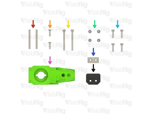
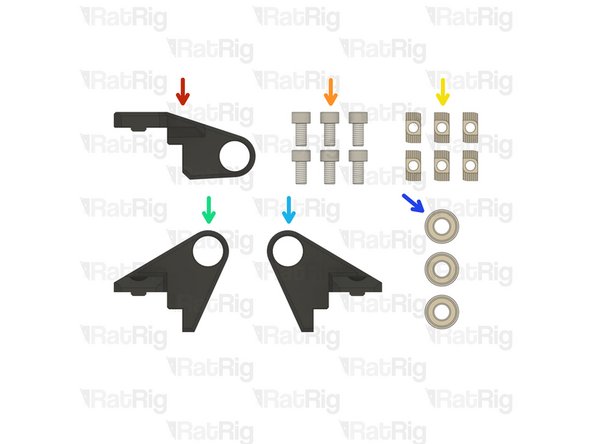
1x bed_arm_right_3.1 Printed Part
-
1x bed_arm_left_3.1 Printed Part
-
4x M3x12 Countersink Screw
-
4x 3x35mm Dowel Pin
-
2x Neodymium Magnet
-
4x M3 Nylon Locking Hex Nut
-
-
-
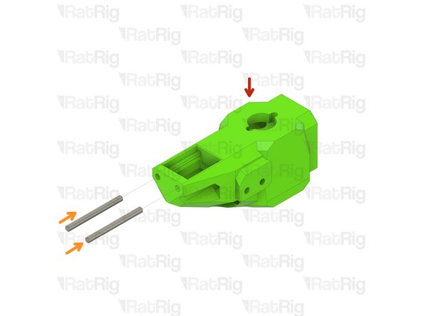
bed_arm_left_3.1 Printed Part
-
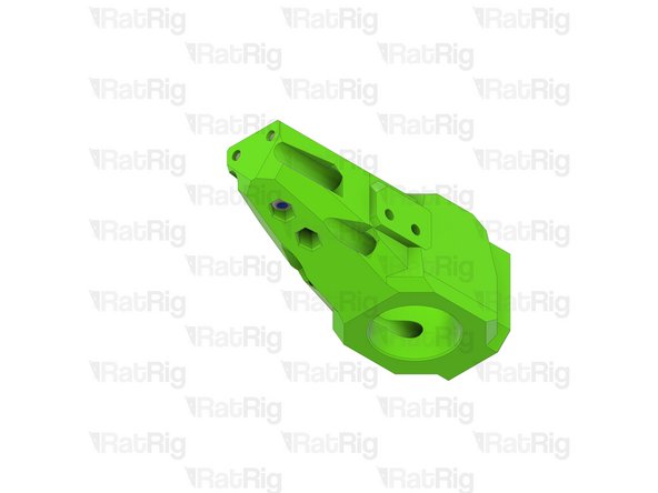
bed_arm_right_3.1 Printed Part
-
3x35mm Dowel Pin
-
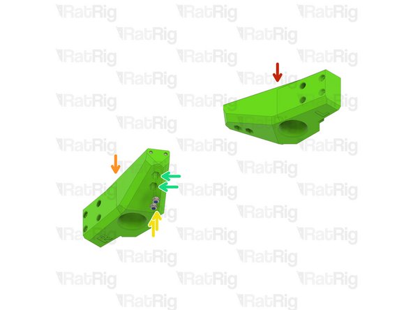
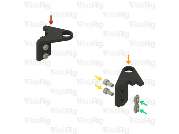
Insert two dowel pins into each arm as shown
-
Please note: The dowel pins are quite a tight fit. It is recommended to use a pair of pliers to install them by twisting each pin in the same manner you would install a screw
-
Do not use excessive force to install the pins as this can cause damage to the printed part
-
-
-
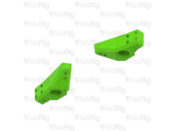
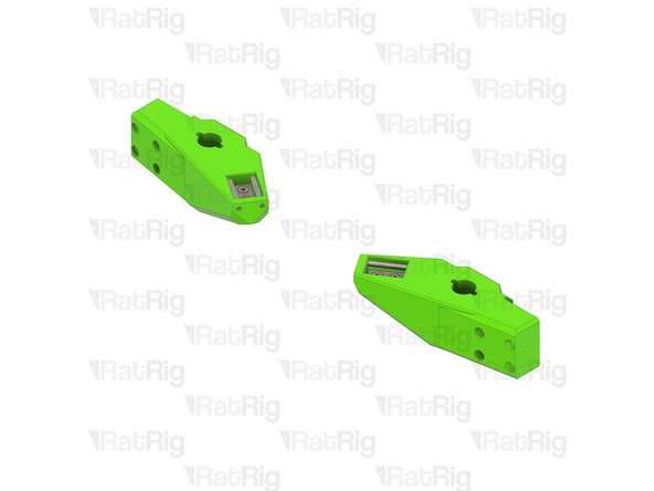
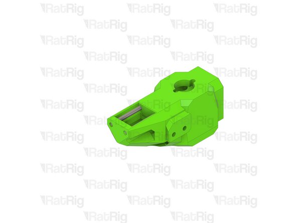
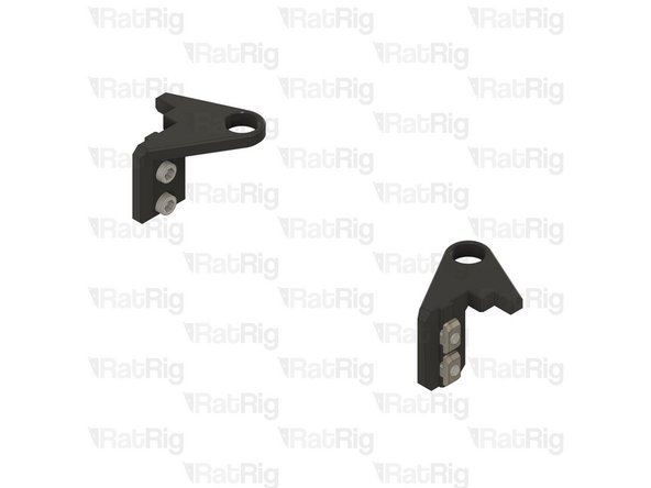
Left Bed Arm Assembly
-
Right Bed Arm Assembly
-
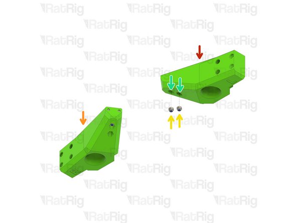
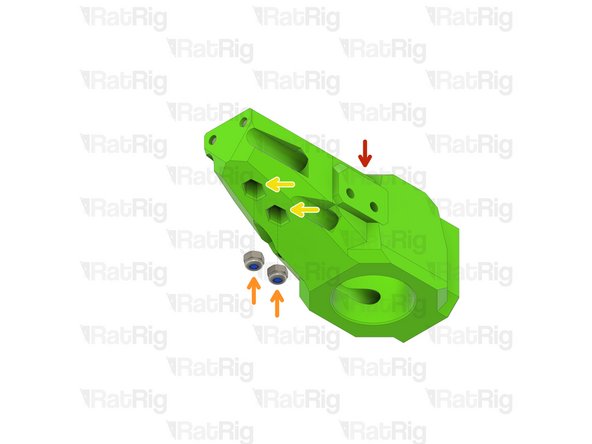
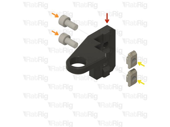
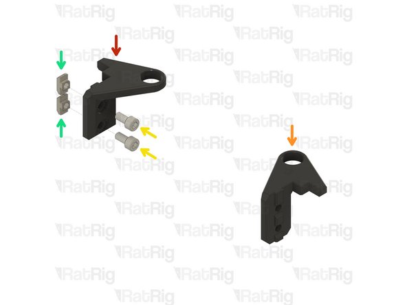
M3 Nylon Locking Hex Nut
-
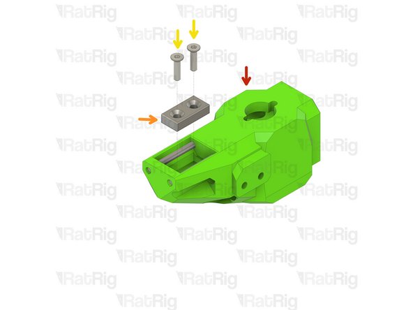
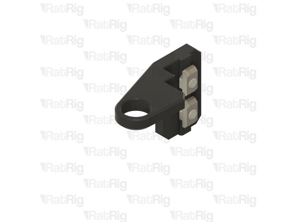
Insert an M3 nut into each marked position
-
-
-
Left Bed Arm Assembly
-
Right Bed Arm Assembly
-
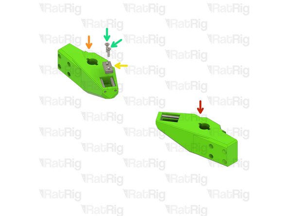
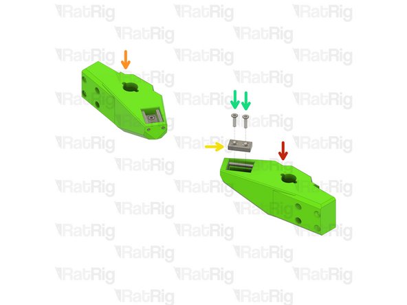
Neodymium Magnet
-
M3x12 Countersink Screw
-
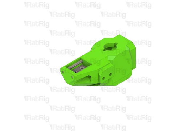
Install two M3x12 countersink screws into each magnet and then install them into the arms as shown
-
Take care not to over tighten the M3x12 screws as you can crack the magnets and/or damage the printed parts
-
Set these assemblies aside until Step 7
-
-
-
3x TR8x4 POM Lead screw Nut
-
3x Rat Rig Bi-Material Lead Screw Decoupler
-
12x M3x8 Cap Head Screw
-
-
-
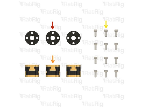
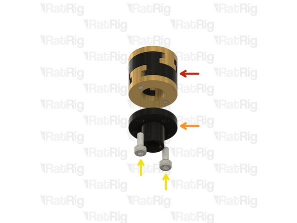
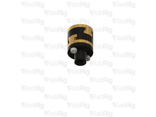
Rat Rig Bi-Material Lead Screw Decoupler
-
TR8x4 POM Lead screw Nut
-
M3x8 Cap Head Screw
-
Assemble all three lead screw decouplers as shown. Set one aside until Step 13, keep the other two for the next step
-
-
-
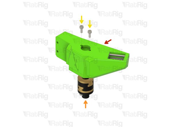
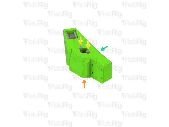
Left bed arm assembly
-
Lead screw decoupler assembly
-
M3x8 Cap Head Screw
-
Install a lead screw decoupler assembly into each arm as shown
-
Take care not to over tighten the M3x8 screws as you damage the printed parts
-
Right bed arm assembly
-
-
-
2x 3x35mm Dowel Pin
-
2x M3x12 Countersink Screw
-
2x M3x35 Cap Head Screw
-
4x M3 Nylon Locking Hex Nut
-
4x M3x12 Cap Head Screw
-
1x Neodymium Magnet
-
1x bed_arm_rear_3.1 Printed Part
-
1x bed_cable_relief_3.1 Printed Part
-
-
-
bed_arm_rear_3.1 Printed Part
-
3x35mm Dowel Pin
-
Insert two dowel pins into the arm as shown
-
Please note: The dowel pins are quite a tight fit. It is recommended to use a pair of pliers to install them by twisting each pin in the same manner you would install a screw
-
Do not use excessive force to install the pins as this can cause damage to the printed part
-
-
-
Rear bed arm assembly
-
M3 Nylon Locking Hex Nut
-
Insert an M3 nut into each marked position
-
-
-
Rear bed arm assembly
-
Neodymium Magnet
-
M3x12 Countersink Screw
-
Install two M3x12 countersink screws into the magnet and then install it into the arm as shown
-
Take care not to over tighten the M3x12 screws as you can crack the magnet and/or damage the printed part
-
-
-
Rear bed arm assembly
-
M3 Nylon Locking Hex Nut
-
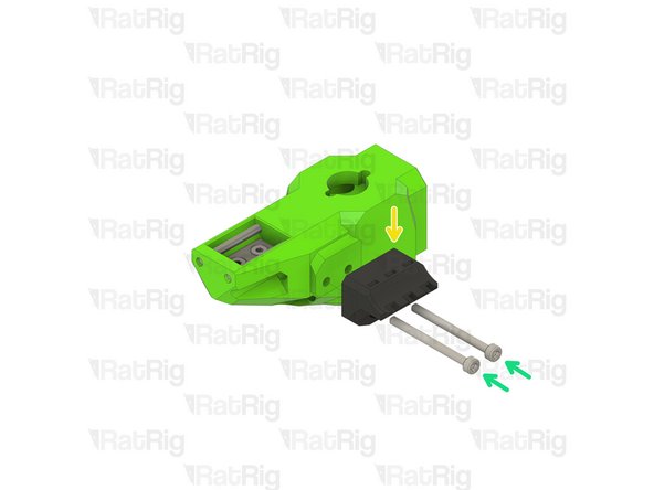
bed_cable_relief_3.1 Printed Part
-
M3x35 Cap Head Screw
-
Install the M3x35 screws through the bed_cable_relief_3.1 printed part, rear bed arm, and fasten them into the M3 nylon locking nuts
-
Take care not to over tighten the M3x35 screws as you can damage the printed parts
-
-
-
V-Core 3.1 Frame Assembly
-
Rear bed arm assembly
-
M3x12 Cap Head Screw
-
Install the M3x12 screws into the arm as shown, then fasten the arm to the rear linear rail carriage
-
Lead screw decoupler assembly from Step 6
-
M3x8 Cap Head Screw
-
Install a lead screw decoupler assembly into the rear arm as shown
-
Take care not to over tighten the M3 screws as you damage the printed part
-
-
-
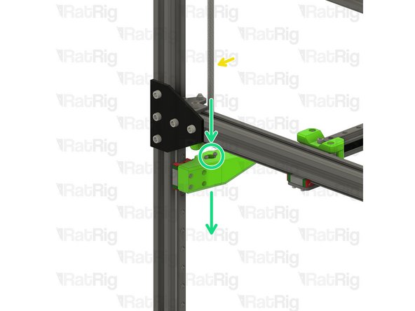
Rear bed arm assembly
-
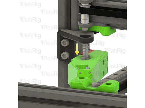
380mm TR8x4 Lead Screw
-
Install the lead screw through the rear bed arm and decoupler
-
Do not force the lead screw through the POM nut on the decoupler as this can cause damage. It should thread through smoothly
-
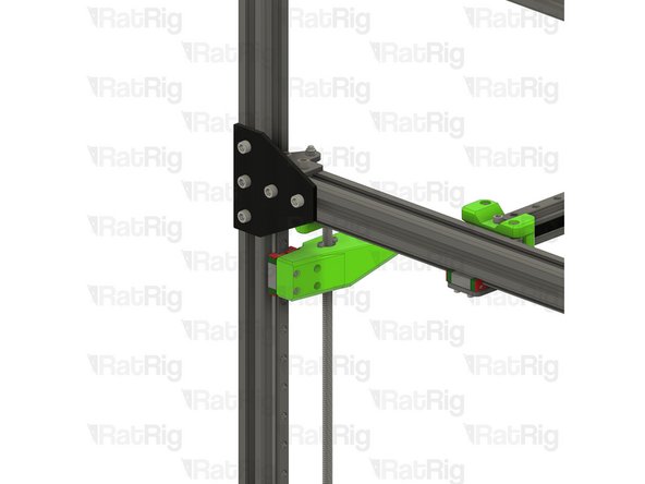
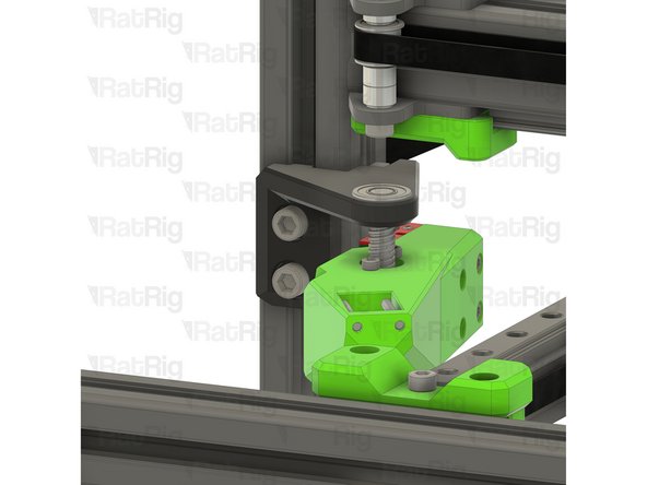
Rigid Lead Screw Coupler
-
Continue threading the lead screw through the arm until it reaches the rigid lead screw coupler on the rear Z-axis motor mount
-
Insert the lead screw fully into the rigid coupler
-
Fasten the marked M3 screw to secure the lead screw to the NEMA17 motor
It's easier to cut the wrap at the middle of the rod and just pull the two halves apart
Andrei Macaveiu - Resolved on Release Reply
If threading is tight, try the other end. When cut, one end usually gets a gunky thread
Donald Fast - Resolved on Release Reply
With my third rod, I found a very fast method to unpack:
The rods are packeged in a square sheet of plastic foil. If you are lucky enough to find the corner(s) of this plastic sheet (on my rods it was somewhere in the center of the rod), carefully follow the edges and unwrap the foil without ripping it.
Think of it as a kid trying to unpack their chocolate easter bunny conserving the aluminium foil.
If you manage to do that, you will have your rod unpacked in seconds.
The easiest way I found is to cut open one side, right at the end of the rod. Then place the rod vertically, the closed end on the table. Grab around the plastic on the top and pull down. Once the rod sticks out a couple of centimeters from the plastic, grab that end and pull the plastic from the other end completely.
Jérôme Pirotte - Resolved on Release Reply
Couldn't agree more with the below comment lol. Was very frustrating.
Nicholas Snyder - Resolved on Release Reply
Removing the plastic wrap from the lead screws may be the second hardest step in a V-Core build after squaring the frame. It's definitely the most annoying lol. If anyone has any tips for how to get it off easily please post them for future builders.
Mark Ewert - Resolved on Release Reply
-
-
-
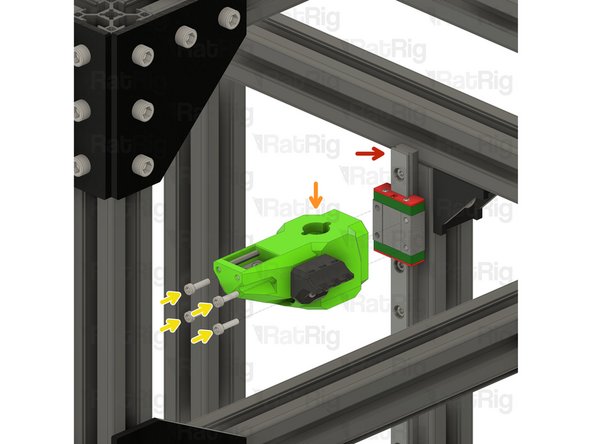
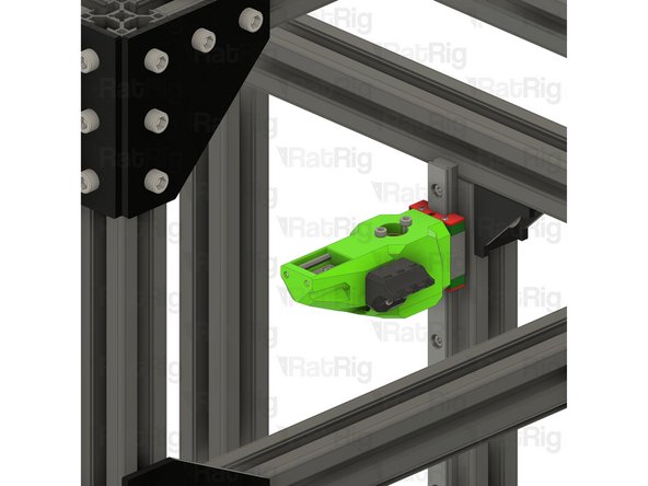
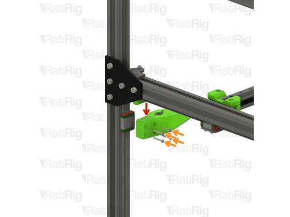
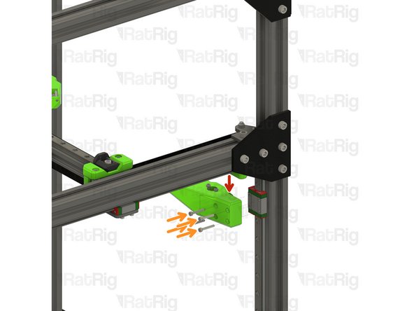
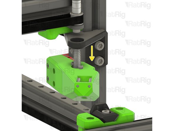
Front right bed arm assembly
-
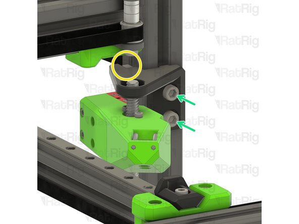
M3x20 Cap Head Screw
-
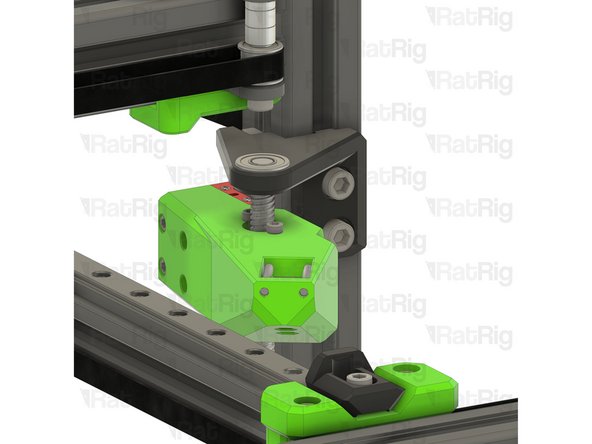
Install each screw through the bed arm assembly as shown, then fasten the arm to the linear rail carriage
-
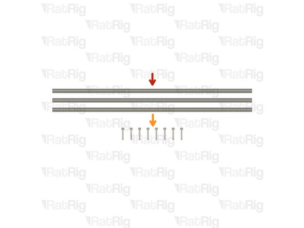
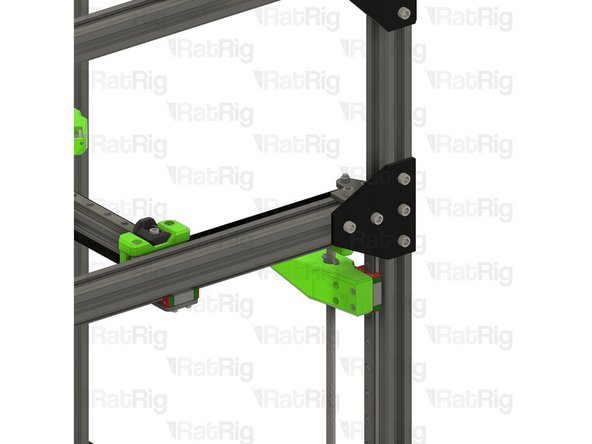
380mm TR8x4 lead screw
-
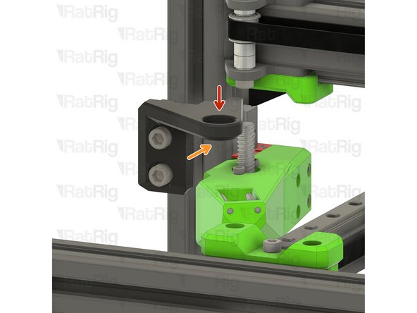
Install the lead screw through the front bed arm and decoupler
-
Do not force the lead screw through the POM nut on the decoupler as this can cause damage. It should thread through smoothly
-
Continue threading the lead screw through the arm until it reaches the rigid lead screw coupler on the front right Z-axis motor mount
-
-
-
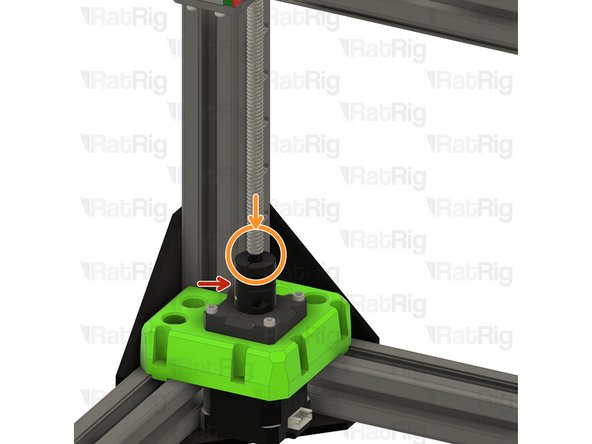
Rigid Lead Screw Coupler
-
Insert the lead screw fully into the rigid coupler
-
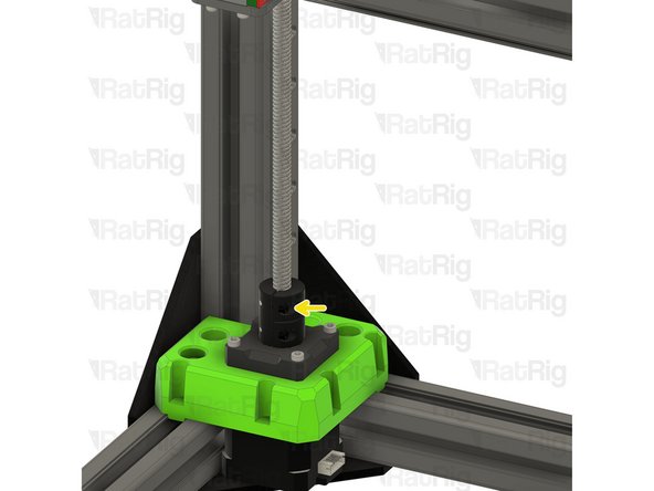
Fasten the marked M3 screw to secure the lead screw to the NEMA17 motor
-
-
-
Front left bed arm assembly
-
M3x20 Cap Head Screw
-
Install each screw through the bed arm assembly as shown, then fasten the arm to the linear rail carriage
-
380mm TR8x4 lead screw
-
Install the lead screw through the front bed arm and decoupler
-
Do not force the lead screw through the POM nut on the decoupler as this can cause damage. It should thread through smoothly
-
Continue threading the lead screw through the arm until it reaches the rigid lead screw coupler on the front left Z-axis motor mount
-
-
-
Rigid Lead Screw Coupler
-
Insert the lead screw fully into the rigid coupler
-
Fasten the marked M3 screw to secure the lead screw to the NEMA17 motor
-
-
-
1x lead_screw_constraint_rear_3.1 Printed Part
-
6x M6x12 Cap Head Screw
-
6x 3030 Drop-in T-Nut - M6
-
1x lead_screw_constraint_front_left_3.1 Printed Part
-
1x lead_screw_constraint_front_right_3.1 Printed Part
-
3x F688ZZ Ball Bearing
-
-
-
lead_screw_constraint_rear_3.1 Printed Part
-
M6x12 Cap Head Screw
-
Insert an M6x12 cap head screw into each position on the lead screw constraint as shown
-
3030 Drop-in T-Nut - M6
-
Loosely thread a 3030 T-Nut onto each of the M6x20 screws. Do not tighten them at this point
-
-
-
lead_screw_constraint_left_3.1 Printed Part
-
lead_screw_constraint_right_3.1 Printed Part
-
M6x12 Cap Head Screw
-
Insert an M6x12 cap head screw into each position on the lead screw constraint as shown
-
3030 Drop-in T-Nut - M6
-
Loosely thread a 3030 T-Nut onto each of the M6x20 screws. Do not tighten them at this point
I also agree - install bearings before mounting the constraint brackets
Mike Schoonmaker - Resolved on Release Reply
-
-
-
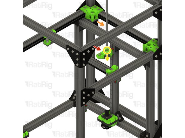
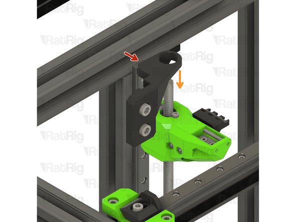
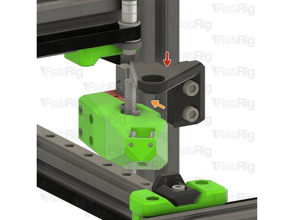
Rear lead screw constraint assembly from Step 21
-
Position the constraint assembly so that the rear lead screw passes through the hole
-
Rotate the constraint assembly clockwise and fit it to the rear 3030 extrusion as shown
-
Push the constraint assembly upwards until it touches the horizontal 3030 extrusion
-
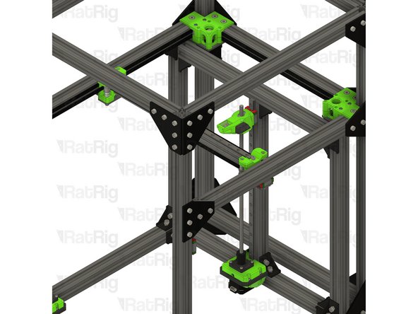
-
-
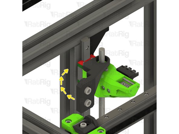
M6x12 Cap Head Screw
-
Fasten both M6x12 screws to secure the constraint assembly to the V-Core 3.1 frame
-
Take care not to over tighten the M6 screws as you damage the printed part
-
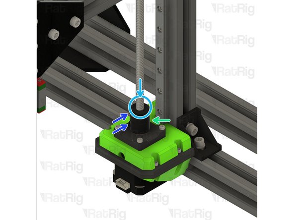
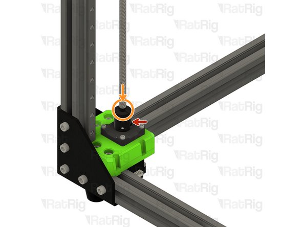
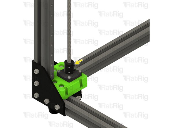
F688ZZ Ball Bearing
-
Fit the bearing onto the lead screw and into the constraint assembly as shown
An alternative to flexing the rear screw is to lay the Ratrig along its right side, and then instead of having the t-nuts loosely screwed onto the M6x12 screws, place the t-nuts in the groove of the aluminum extrusion. (If the Ratrig weren't on its side, the t-nuts wouldn't stay in place, of course.)
If you preinstall the bearings onto the constraints (which you should, trust me), you'll have to flex the rear lead screw a bit to fit this on. I advise that you put the arm at its lowest point to give the screw the most flexibility.
Kal Woodside - Resolved on Release Reply
-
-
-
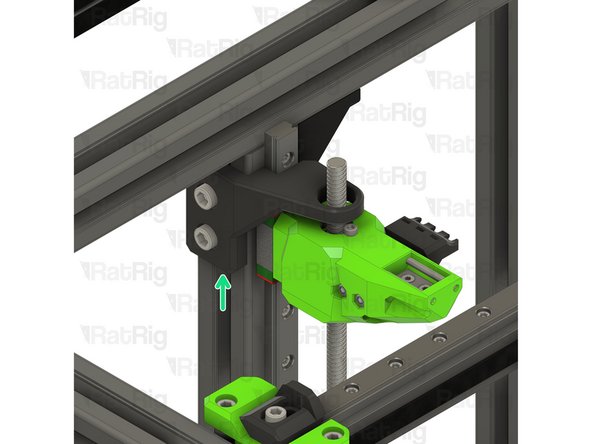
Right lead screw constraint assembly from Step 22
-
Fit the constraint assembly to the frame as shown
-
Push the constraint assembly downwards until its top is flush with the top of the linear rail
-
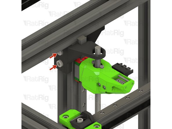
Fasten both M6x12 screws to secure the constraint assembly to the V-Core 3.1 frame
-
-
-
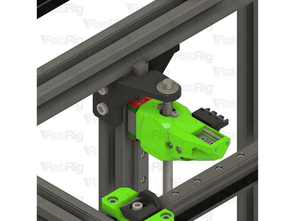
F688ZZ Ball Bearing
-
Fit the bearing onto the lead screw and into the constraint assembly as shown
-
-
-
Left lead screw constraint assembly from Step 22
-
Fit the constraint assembly to the frame as shown
-
Push the constraint assembly downwards until its top is flush with the top of the linear rail
-
Fasten both M6x12 screws to secure the constraint assembly to the V-Core 3.1 frame
-
-
-
F688ZZ Ball Bearing
-
Fit the bearing onto the lead screw and into the constraint assembly as shown
-


Cancel: I did not complete this guide.
18 other people completed this guide.