-
-
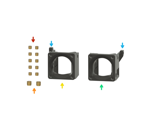
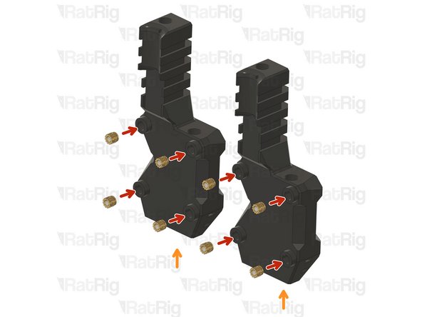
16x Heat Insert M3
-
rr_toolhead_vc4_back_idex_t0
-
rr_toolhead_vc4_back_idex_t1
-
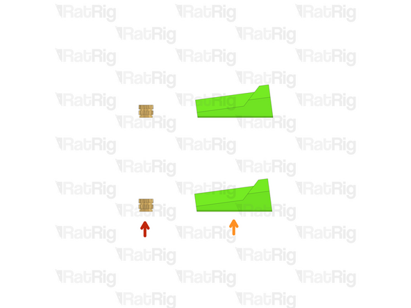
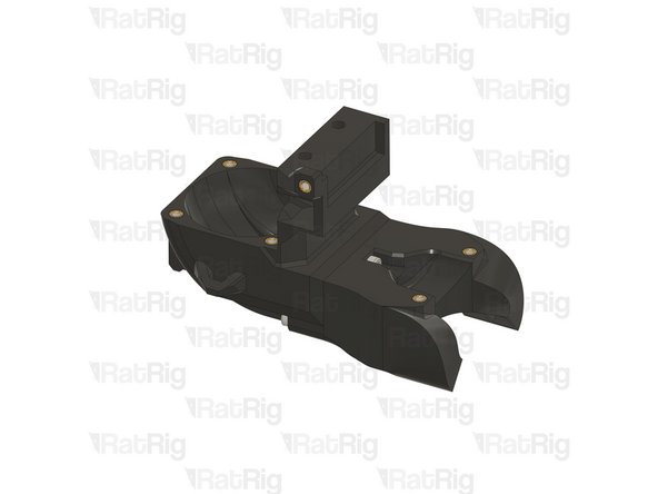
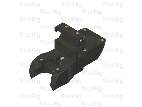
Remove the AGAD parts (Anti Gravity Assistance Device)
-
Rat Rig avoids supports at all costs, so we're introducing the AGAD as this printed part needs to have a very precise overhang.
-
-
-
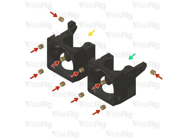
rr_toolhead_vc4_back_idex_t0
-
rr_toolhead_vc4_back_idex_t1
-
16x Heat Insert M3
-
-
-
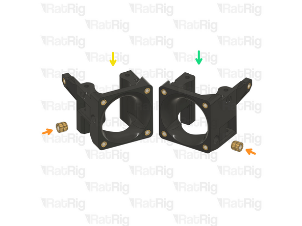
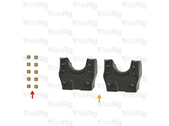
10x Heat Insert M3
-
2x Heat Insert M4
-
rr_toolhead_vc4_idex_idex_t0
-
rr_toolhead_vc4_idex_idex_t1
-
The only differences between the two printed parts are the endstop location and the M4 belt clamp heat insert. For T0, these elements are positioned on the left, while for T1, they are positioned on the right.
-
-
-
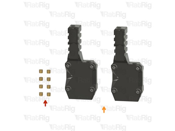
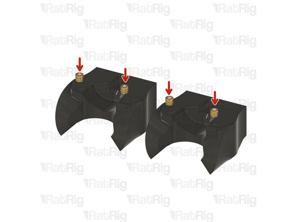
8x Heat Insert M3
-
2x rr_vc4_toolhead_toolboard_vertical
-
-
-
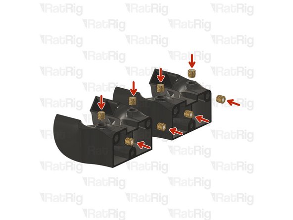
2x Heat Insert M3
-
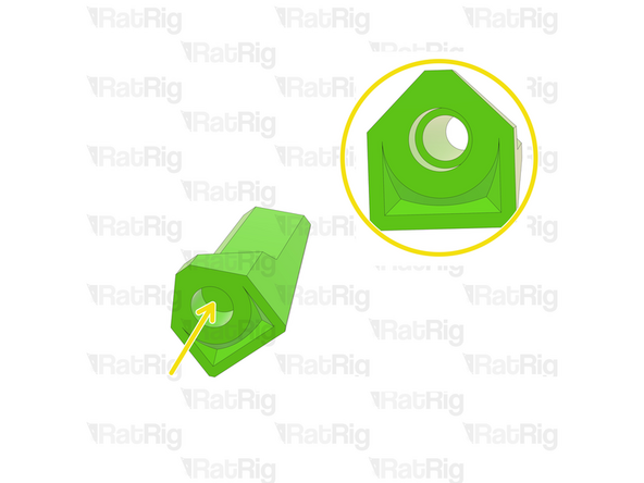
2x rr_toolhead_vc4_back_clamp
-
Clean the sacrificial layers on the rr_vc4_toolhead_back_clamp parts, obtaining a clean passthrough hole.
-
-
-
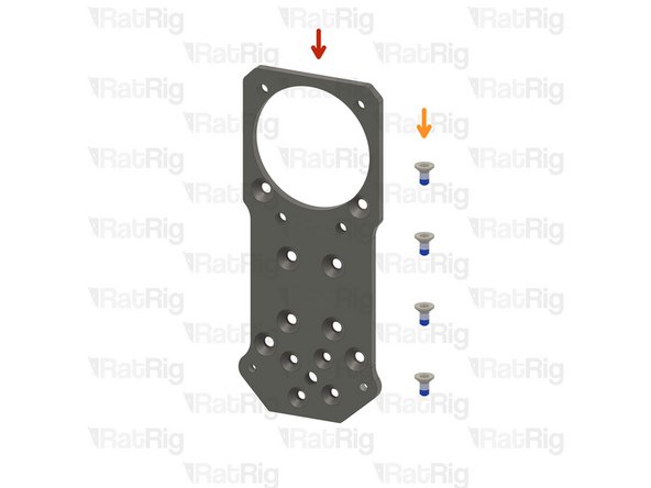
1x Rat Rig toolhead plate
-
4x M3x6 Countersink Screw with applied thread locker
-
-
-
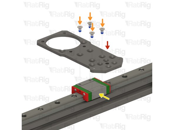
Rat Rig toolhead plate
-
4x M3x6 Countersink Screw
-
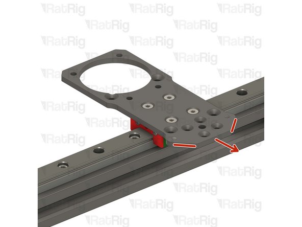
Tighten the M3x6 Countersink Screws to secure the plate to the carriage.
-
Pay attention to the orientation of the metal plate, having the pointy side towards the front of the printer, chamfered holes up.
-
Avoid using a ball end hex key, as they are more prone to damaging the sensitive M3 countersink screw head.
-
After tightening the screws, it is essential to verify that the X carriage retains its free movement. Excessive tightening of the screws may lead to the binding of the carriage.
-
-
-
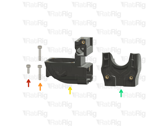
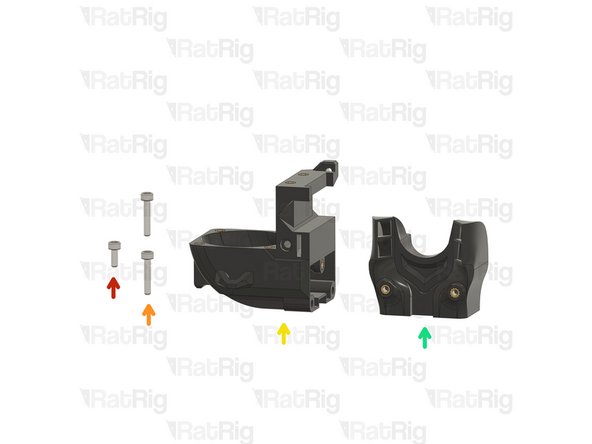
1x M3x8 Cap Head Screw
-
2x M3x16 Cap Head Screw
-
1x rr_toolhead_vc4_back_idex_t0 assembly
-
1x rr_toolhead_vc4_duct_idex assembly
-
-
-
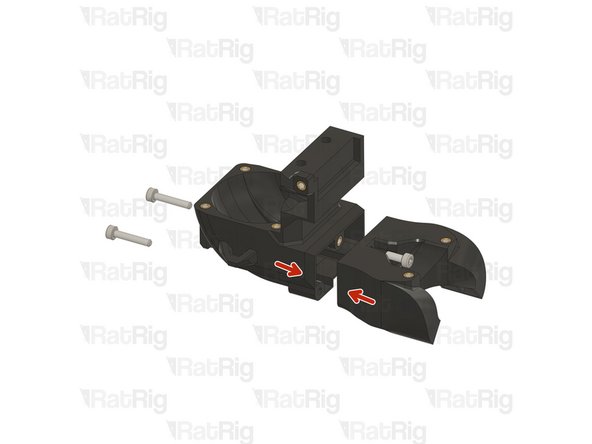
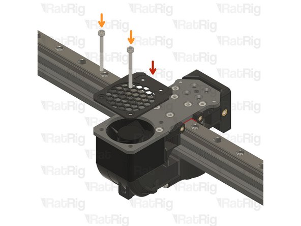
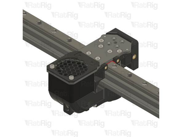
Join the two assemblies together, ensuring they are flush.
-
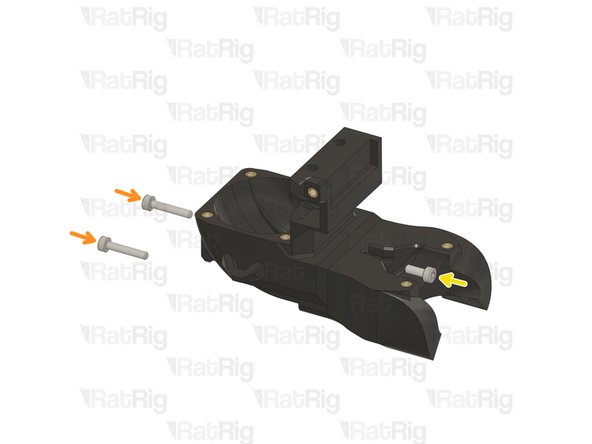
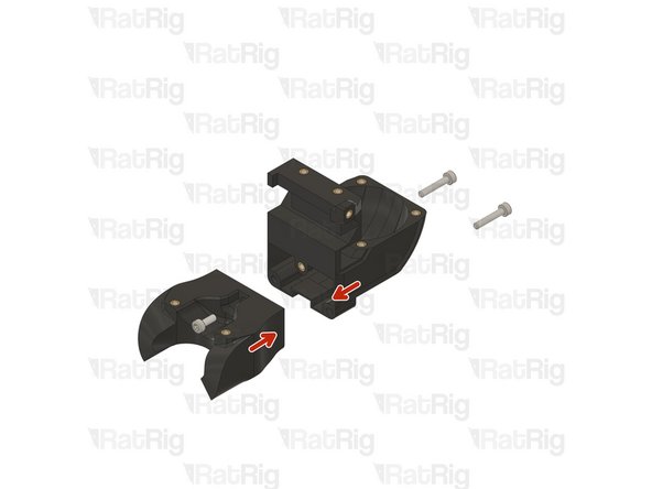
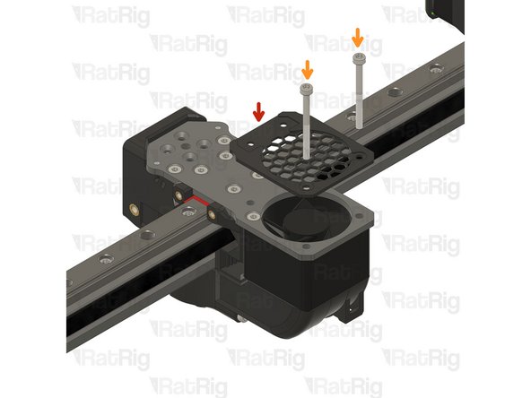
2x M3x16 Cap Head Screw
-
Insert the M3x16 screws through the back part and tighten them into the duct.
-
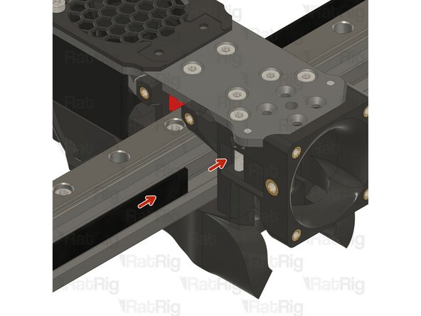
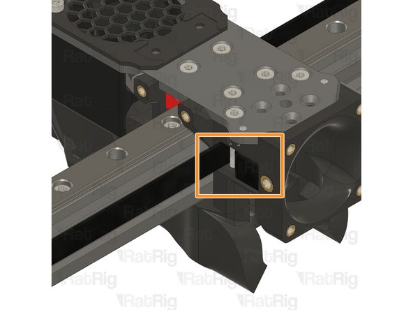
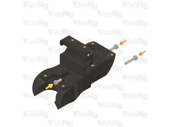
M3x8 Cap Head Screw
-
Feed the M3x8 screw from the opposite side and secure the parts together.
-
Take care not to over tighten the screws as you can damage the printed parts.
-
-
-
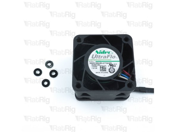
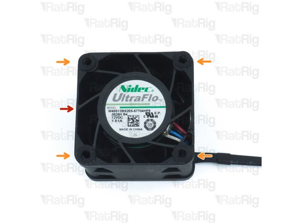
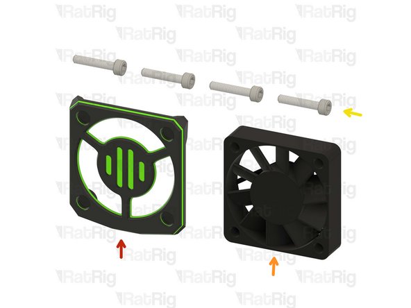
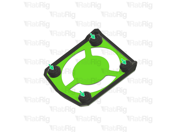
4028 Cooling fan
-
Remove the four rubber spacers on the 4028 Part Cooling Fan
-
-
-
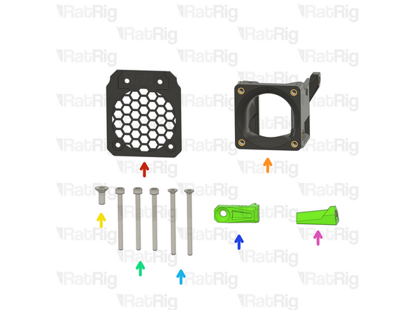
rr_vc4_toolhead_fan_grille
-
rr_vc4_toolhead_front_idex_t0 assembly
-
M4x10 Countersink Screw
-
3x M3x35 Cap Head Screw
-
2x M3x40 Countersink Screw
-
2x rr_vc4_toolhead_front_clamp
-
rr_toolhead_vc4_back_clamp assembly
-
-
-
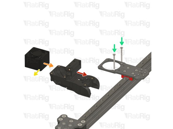
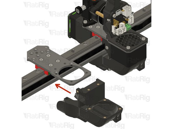
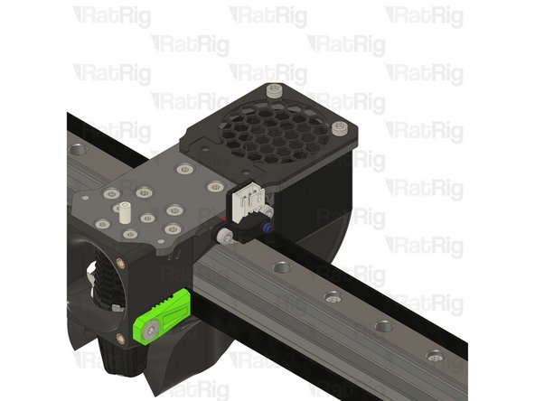
Back part & duct sub-assembly
-
4028 Part Cooling Fan
-
Pay special attention to the fan airflow, it should blow the air towards the cooling duct. Most fans have a small arrow indicating the airflow.
-
Point the fan wires to this side.
-
2x M3x35 Countersink Screw
-
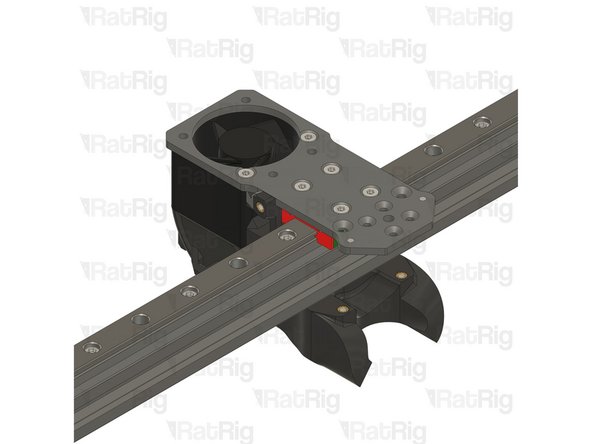
Feed the M3x35 screws into the toolhead plate, through the 4028 part cooling fan and tighten them into the printed sub-assembly.
-
Take care not to over tighten the screws as you can damage the printed parts.
-
Avoid using a ball end hex key, as they are more prone to damaging the sensitive M3 countersink screw head.
-
-
-
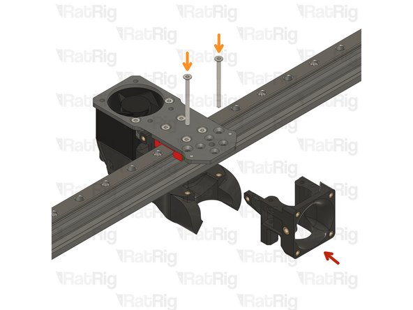
rr_vc4_toolhead_front_idex_t0 assembly
-
2x M3x35 Countersink screw
-
The M3x40 countersink screws must go through the holes on the front assembly and thread into the duct assembly.
-
Take care not to over tighten the screws as you can damage the printed parts
-
Avoid using a ball end hex key, as they are more prone to damaging the sensitive M3 countersink screw head.
-
-
-
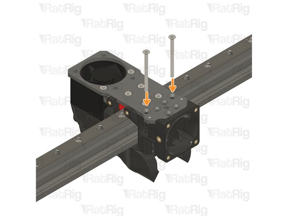
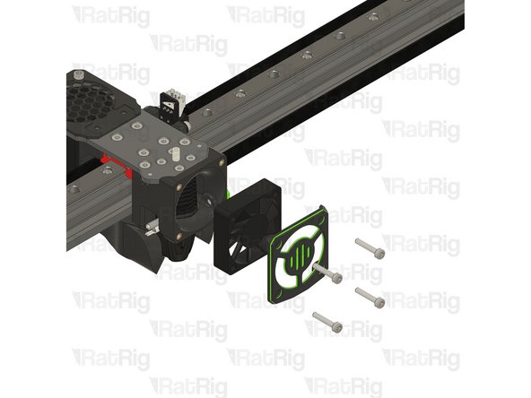
rr_vc4_toolhead_fan_grille
-
2x M3x35 Cap Head Screw
-
Feed the M3x35 cap head screws through the grille (pay close attention to its orientation), the aluminium plate and the 4028 fan, tightening them into the back printed part.
-
Take care not to over tighten the screws as you can damage the printed parts
-
Avoid using a ball end hex key, as they are more prone to damaging the sensitive M3 countersink screw head.
-
-
-
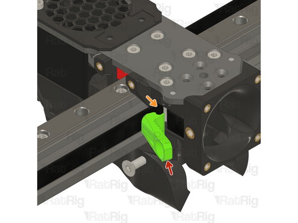
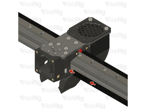
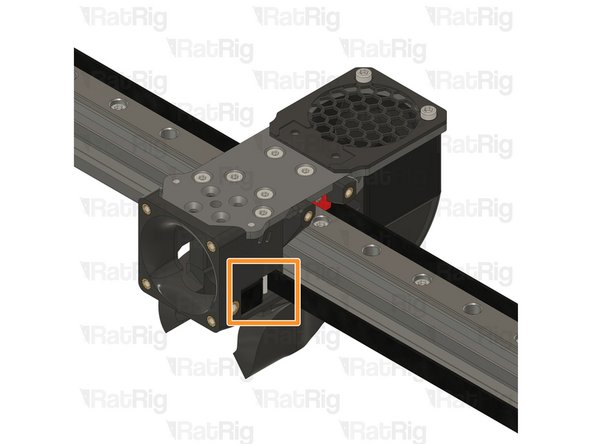
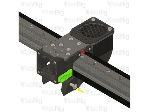
Insert the belt in the designated slot, and ensure the belt end is fed from behind the screw.
-
Pull the belt end and gently place it inside the groove.
-
The belt teeth must be facing the front of the machine.
-
-
-
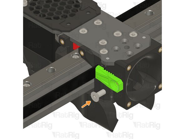
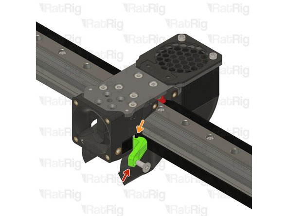
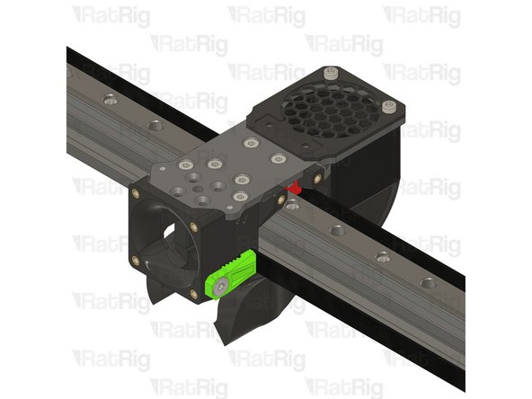
Rat Rig toolhead front belt clamp
-
Lever the belt clamp against the exposed screw section and place it inside the belt slot.
-
M4x10 Countersink Screw
-
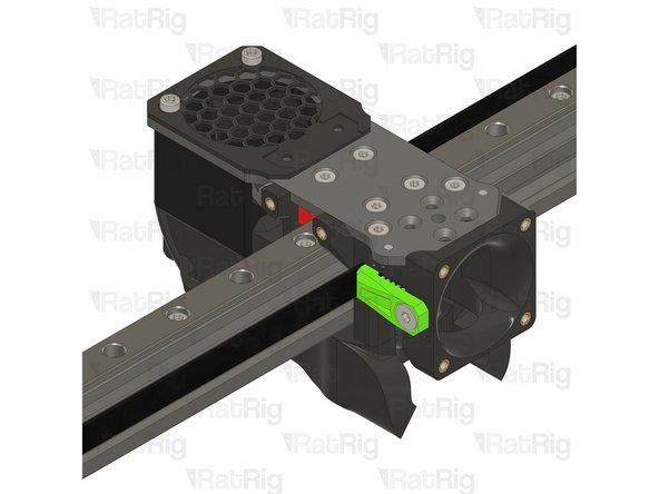
Tighten the M4x10 screw making sure the teeth of the belt clamp mesh with the belt
-
Pay attention to seating the notch on the belt clamp on the exposed screw section. Pull on the belt to make sure it's secured properly.
-
Take care not to over tighten the screws as you can damage the printed parts
-
-
-
Feed the belt inside the slot on the back part of the toolhead.
-
Leave 10-20mm of the belt tip extending out to allow for easy manipulation during assembly.
-
Rat Rig toolhead back belt clamp
-
M3x35 Cap Head Screw
-
Tighten the M3x35 cap head screw while securely holding the belt end to prevent it from being pulled in.
-
Cut the excess belt.
-
-
-
Phaetus Rapido V2 UHF Hotend
-
4x M2.5x6 Countersink Screw
-
PTFE tube - 24.5mm
-
Remove the two countersink screws on top of the rapido
-
Remove the V6-style adapter, it is not required for the RatRig toolhead
-
-
-
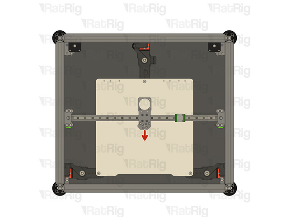
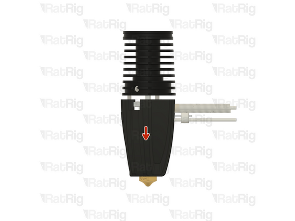
This image references the single toolhead version, but the procedure is the same. The goal is to verify if the rapido wires align with the toolhead slot.
-
Phaetus Rapido V2 UHF
-
Place the Phaetus Rapido V2 UHF Hotend on the plate, making sure to route the cables through the designated slot
-
Look from above and see if all four holes line up correctly.
-
All the holes on the plate, hotend and printed part should line up:
-
If they align skip to Step 26
-
If they don't align follow the next steps
-
-
-
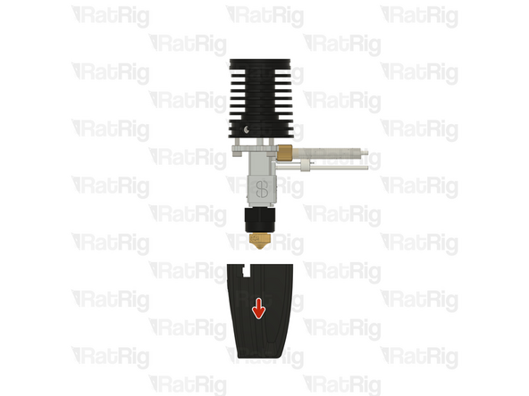
If the cables of your Rapido 2 hotend don't align perfectly with the toolhead slot, please follow the next steps:
-
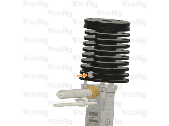
Push down on the silicone sock to remove it
-
Loosen the set screw on the heatsink
-
Do not remove it completely to avoid losing it
-
-
-
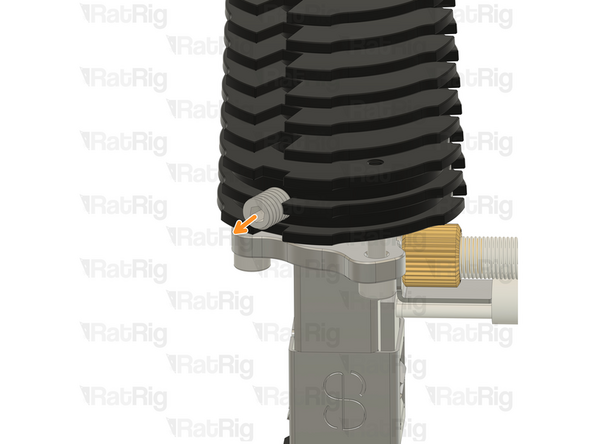
Remove the 2.5mm Cap Head Screws from the hotend
-
Carefully rotate the heatsink until the three screw holes align again.
-
There isn't a way to tell how much you need to rotate you hotend, it might be just 120º or it might be 240º. It's a matter of trial and error.
-
-
-
Insert the 2.5mm Cap Head Screws back in and tighten them.
-
DO NOT overtighten the screws, they are only 2.5mm and will break if excessive force is applied.
-
Tighten the set screw back in
-
DO NOT overtighten the screw, if excessive force is applied the heatbreak will be permanently damaged.
-
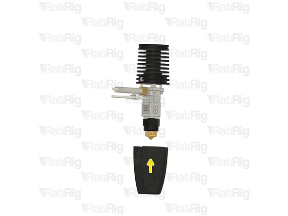
Put the socket back on.
-
Try to insert the hotend on the toolhead and see if the cables align with the designated slot, if not, repeat Steps 21, 22 and 23 and try a different angle in Step 22
-
-
-
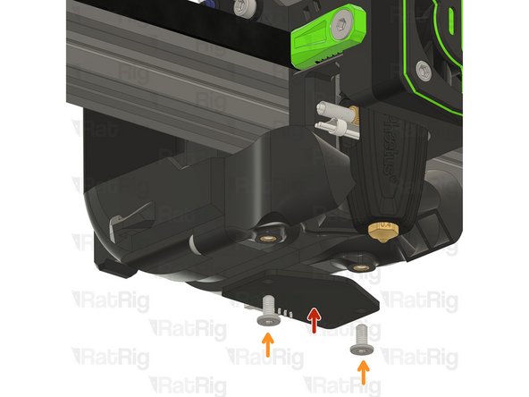
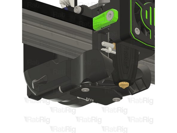
4x M2.5x6 Countersink Screw
-
Tighten the M2.5x6 Countersink Screws to secure the hotend to the plate.
-
Avoid using a ball end hex key, as they are more prone to damaging the sensitive M2.5 countersink screw head.
-
PTFE tube - 24.5mm
-
Insert the PTFE tube in to the marked hole and push it until it stops.
-
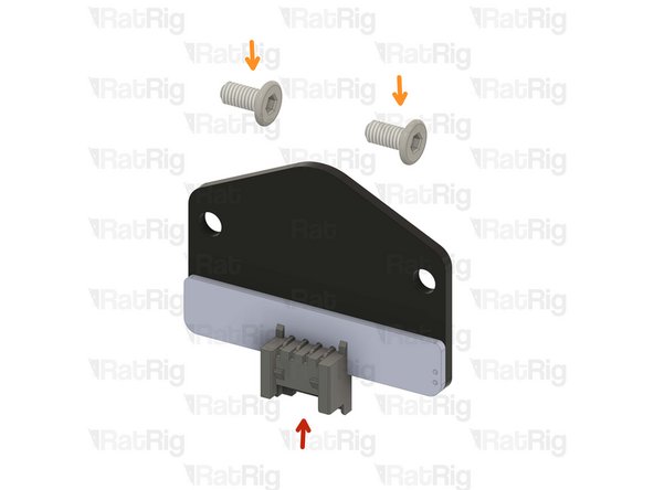
-
-
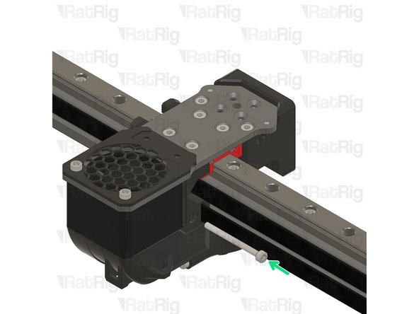
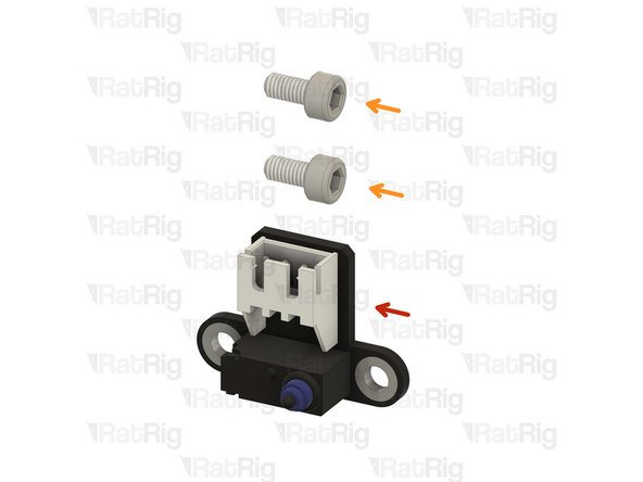
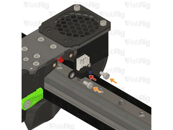
Rat Rig X Endstop
-
2x M3x6 Cap Head Screw
-
Tighten the M3x6 screws to secure the X endstop to the toolhead.
-
Take care not to over tighten the M3x6 screws as you can damage the printed parts.
-
-
-
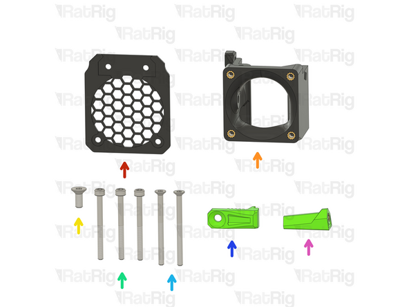
1x rr_vc4_toolhead_shroud
-
40x10mm 24V Axial Fan
-
4x M3x16 Cap Head Screw
-
Remove the sacrificial layers from the back of the rr_vc4_toolhead_shroud
-
-
-
Rat Rig toolhead fan shroud printed part
-
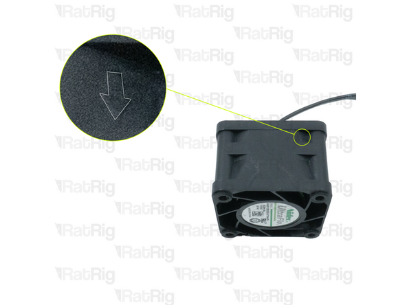
40x10mm 24V Axial Fan
-
The wires should be positioned where the arrow points.
-
4x M3x16 Cap Head Screw
-
Insert the M3x16 screws into the Rat Rig toolhead shroud printed part, through the 40mm fan, and fasten them into the Rat Rig toolhead front.
-
Take care not to over tighten the M3x16 screws as you can damage the printed parts.
-
Pay special attention to the fan airflow, it should blow the air towards the hot end heat sink. Most fans have a small arrow indicating the airflow. If not, the the fan label should be facing the hotend.
-
-
-
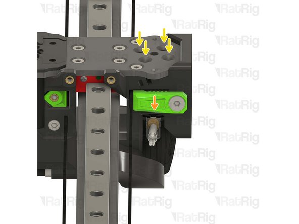
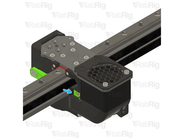
Beacon Rev H Low Profile
-
Rat Rig recommends connecting the beacon's cable before mounting it to ensure the connector is fully and securely inserted.
-
2x M3x6 Wafer Head Screw
-
Tighten the M3x6 screws to secure the Beacon to the toolhead.
-
Take care not to over tighten the M3x6 screws as you can damage the PCB and the printed parts.
-
-
-
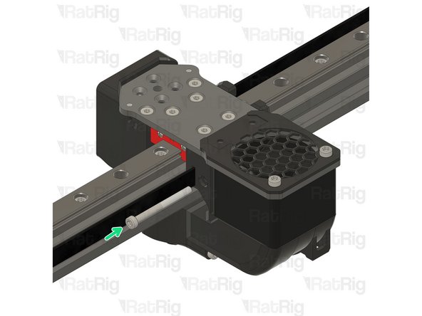
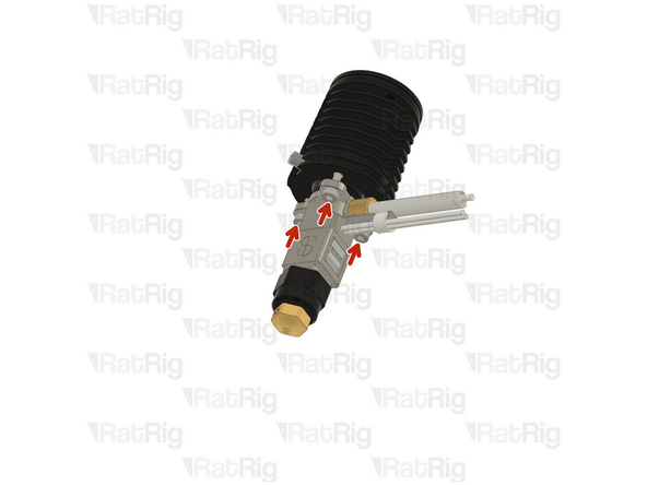
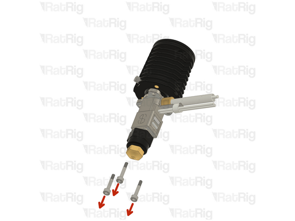
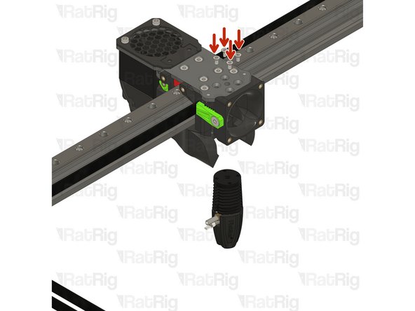
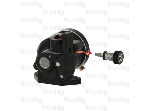
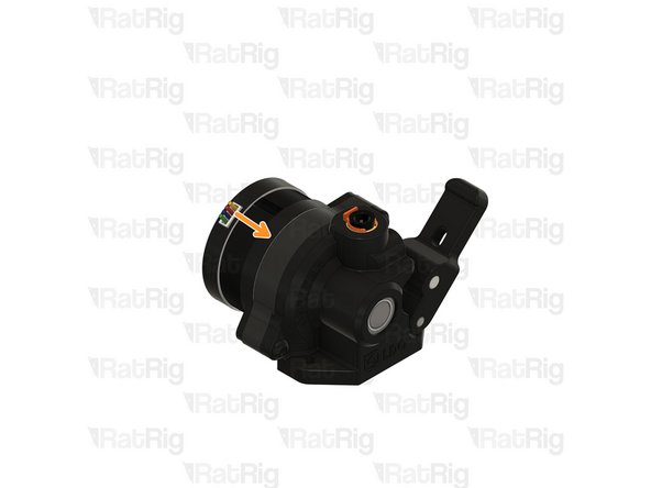
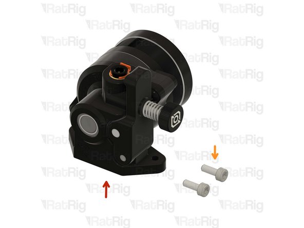
Remove the tensioning screw
-
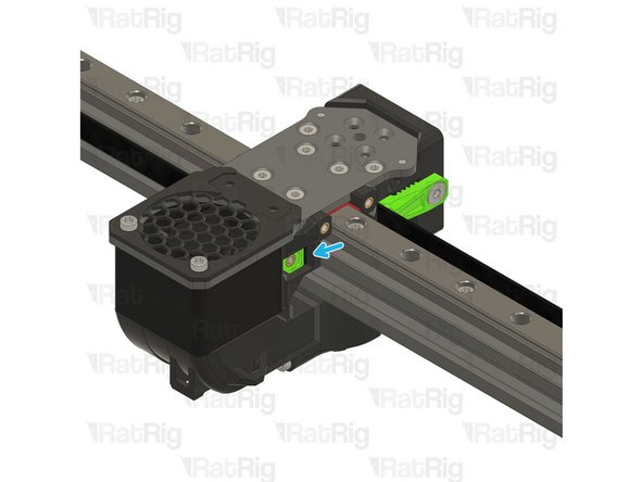
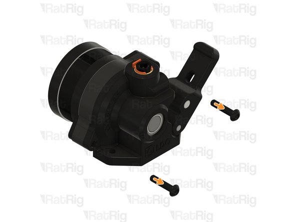
Remove the two front screws
-
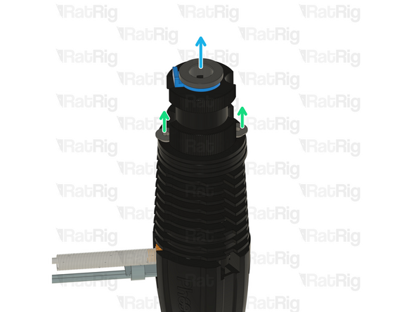
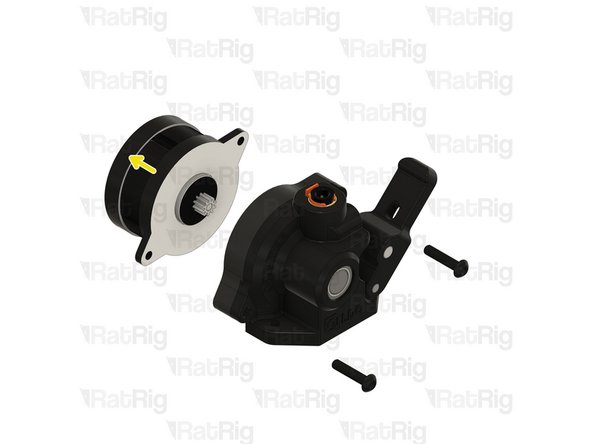
Carefully detach (or rotate) the stepper motor from the housing
-
-
-
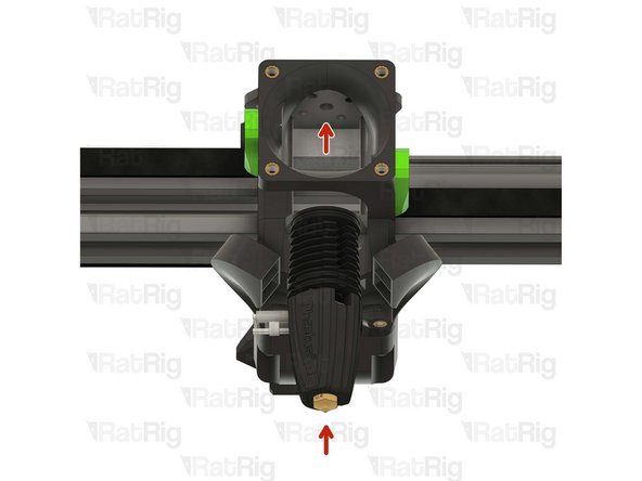
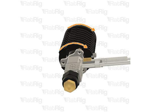
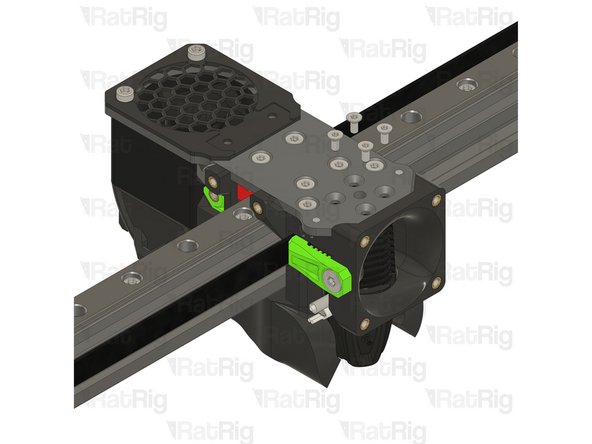
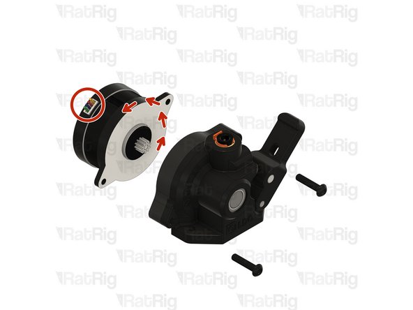
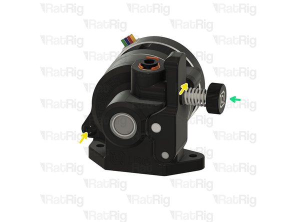
Rotate the stepper motor 180º until the wires come out from the top.
-
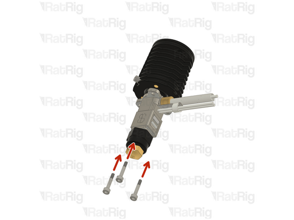
Carefully reinstall the stepper on the housing.
-
Install the front screws
-
Install the tensioning screw
-
-
-
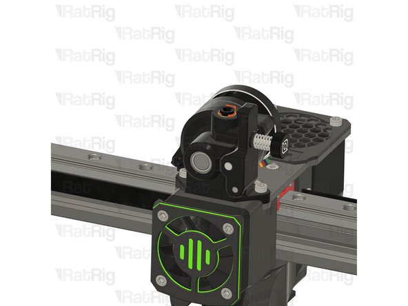
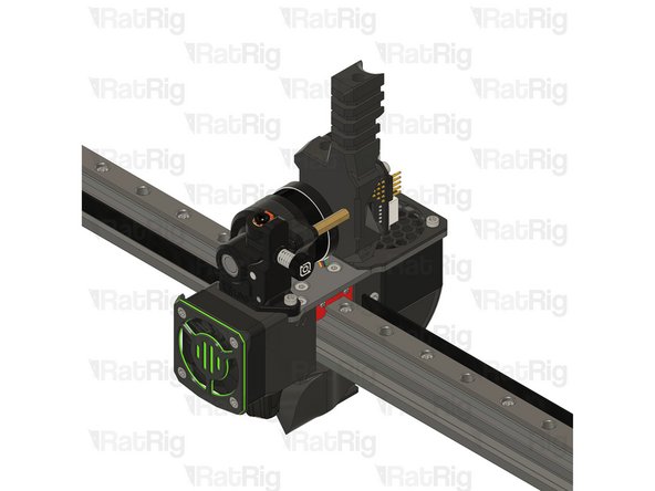
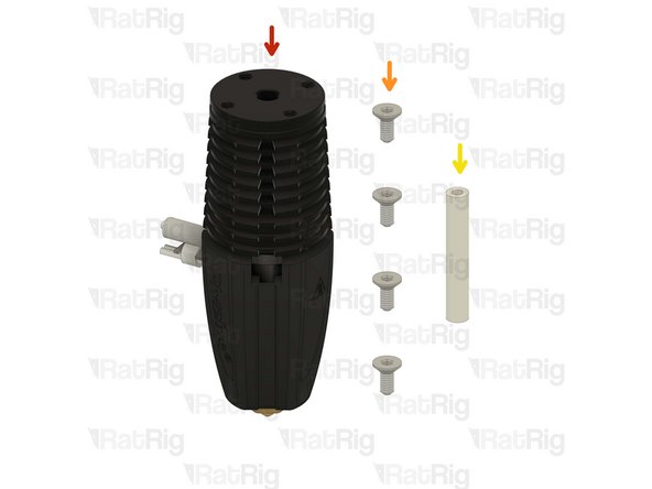
LDO Orbiter V2
-
2x M3x8 Cap Head Screw
-
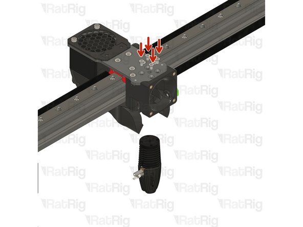
Carefully align the extruder with the PTFE tube.
-
Insert the M3x8 screws into the LDO Orbiter V2 and fasten them to the Rat Rig toolhead plate.
-
Take care not to over tighten the M3x8 screws as you can strip the toolhead plate threads
-
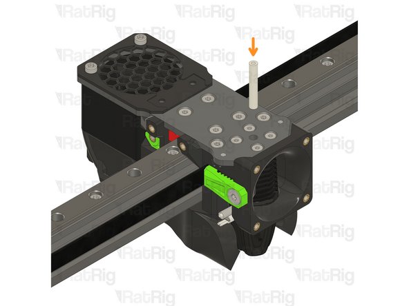
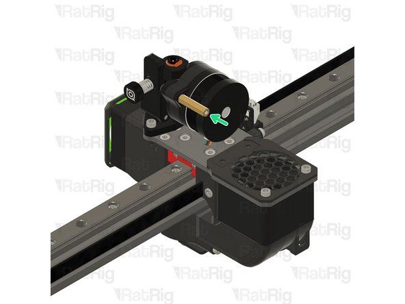
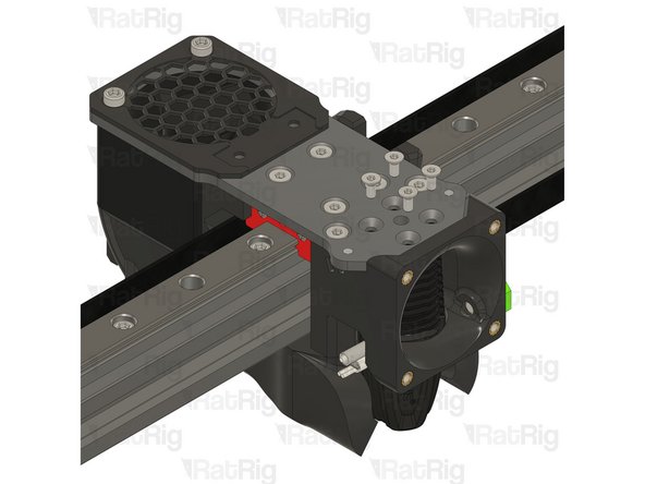
Thread the hex standoff on to the LDO Orbiter V2 screw.
-
Do not overtighten the hex standoffs. They are brass and it is possible to strip the threads.
-
-
-
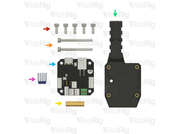
5x M3x8 Cap Head Screw
-
2x M3x35 Cap Head Screw
-
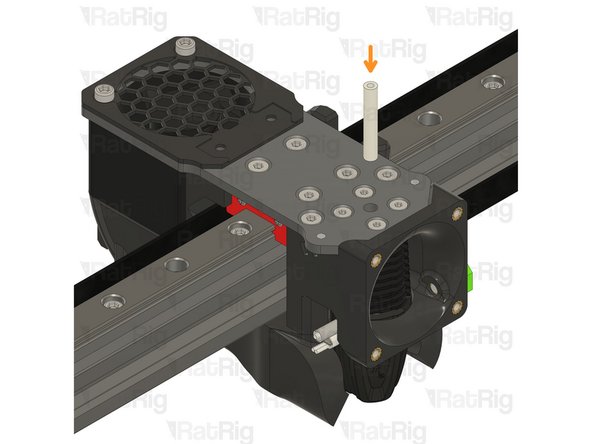
1x Hex standoff M3x20x4.5
-
rr_vc4_toolhead_toolboard_vertical
-
BIGTREETECH EBB42 USB/CAN TOOLBOARD V1.2
-
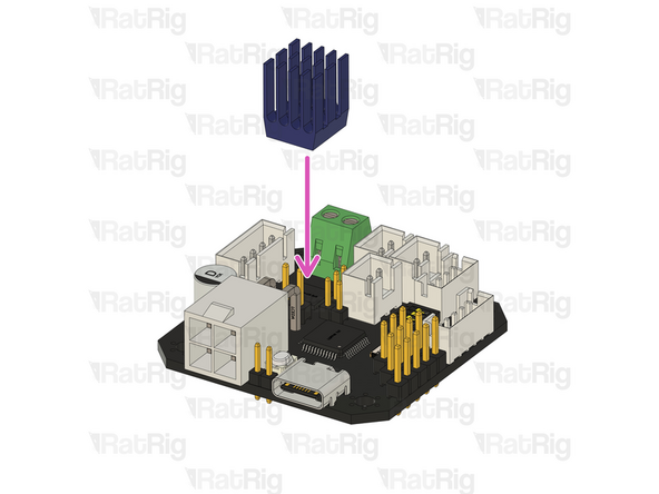
TMC2209 driver heatsink (included in the EBB42 box)
-
Remove the adhesive backing from the heatsink and gently press it onto the TMC2209 driver.
-
-
-
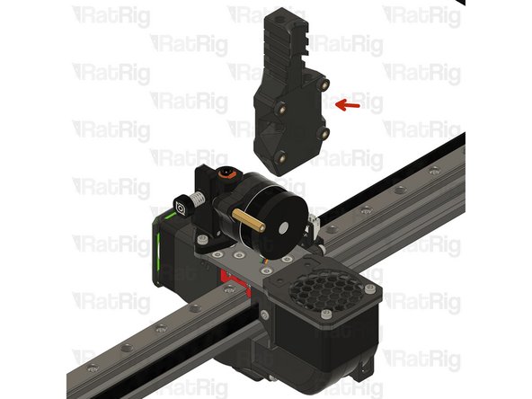
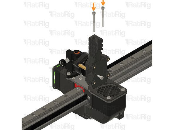
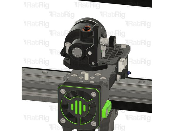
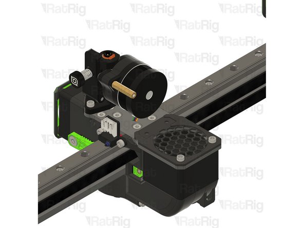
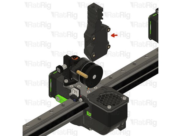
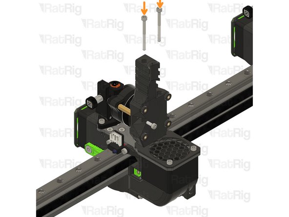
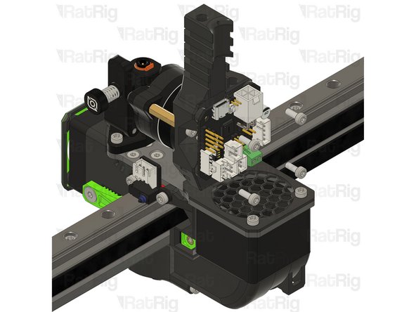
rr_vc4_toolhead_toolboard_vertical
-
Insert the M3x35 screws into the Rat Rig toolhead vertical toolboard mount printed part and secure it onto the toolhead.
-
Take care not to over tighten the M3x35 screws as you can damage the printed parts.
-
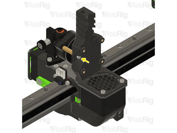
1x M3x8 Cap Head Screw
-
Insert the M3x8 screw through the printed part and into the thread to attach it to hex standoff.
-
-
-
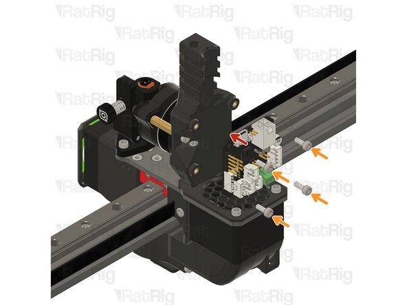
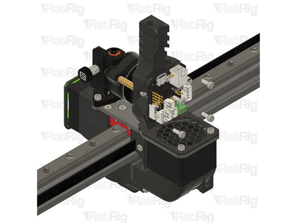
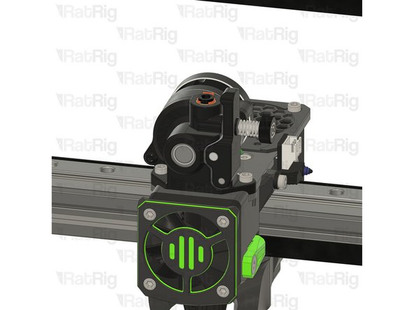
BIGTREETECH EBB42 USB/CAN TOOLBOARD V1.2
-
4x M3x8 Cap Head Screw
-
Insert the M3x8 screws into the toolboard and thread them into the Rat Rig toolhead vertical toolboard mount printed part
-
-
-
1x Rat Rig toolhead plate
-
4x M3x6 Countersink Screw with applied thread locker
-
-
-
Rat Rig toolhead plate
-
4x M3x6 Countersink Screw
-
Second linear rail carriage
-
Tighten the M3x6 Countersink Screws to secure the plate to the carriage.
-
Pay attention to the orientation of the metal plate, having the pointy side towards the front of the printer, chamfered holes up.
-
Avoid using a ball end hex key, as they are more prone to damaging the sensitive M3 countersink screw head.
-
After tightening the screws, it is essential to verify that the X carriage retains its free movement. Excessive tightening of the screws may lead to the binding of the carriage.
-
-
-
1x M3x8 Cap Head Screw
-
2x M3x16 Cap Head Screw
-
1x rr_toolhead_vc4_back_idex_t1 assembly
-
1x rr_toolhead_vc4_duct_idex assembly
-
-
-
Join the two assemblies together, ensuring they are flush.
-
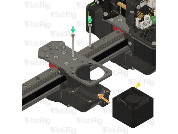
2x M3x16 Cap Head Screw
-
Insert the M3x16 screws through the back part and tighten them into the duct.
-
M3x8 Cap Head Screw
-
Feed the M3x8 screw from the opposite side and secure the parts together.
-
Take care not to over tighten the screws as you can damage the printed parts.
-
-
-
4028 Cooling fan
-
Remove the four rubber spacers on the 4028 Part Cooling Fan
-
-
-
rr_vc4_toolhead_fan_grille
-
rr_vc4_toolhead_front_idex_t1 assembly
-
M4x10 Countersink Screw
-
3x M3x35 Cap Head Screw
-
2x M3x40 Countersink Screw
-
2x rr_vc4_toolhead_front_clamp
-
rr_toolhead_vc4_back_clamp assembly
-
-
-
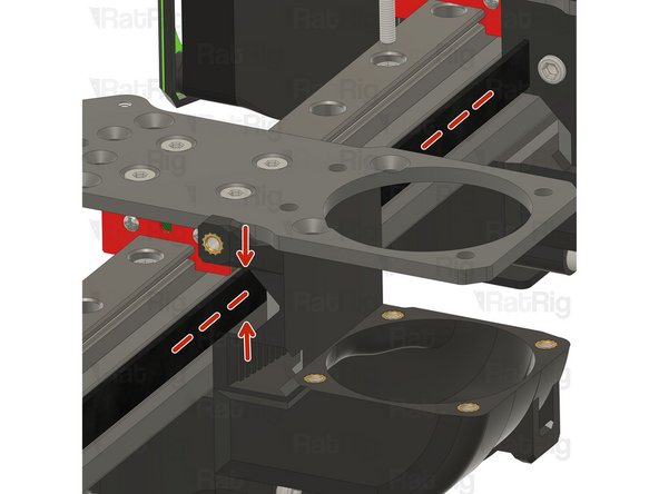
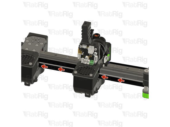
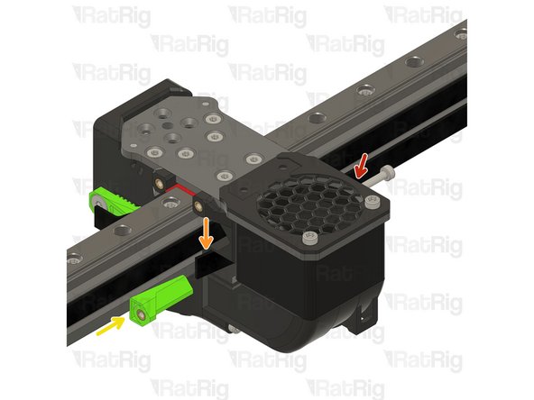
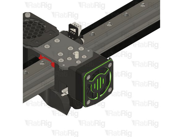
Carefully install the rear component and the duct sub-assembly onto the toolhead plate, ensure that the belt connected to Toolhead T0 is properly positioned and remains clear of Toolhead T1.
-
Take special care to avoid pinching or damaging the T0 belt during the installation process.
-
4028 Part Cooling Fan
-
Pay special attention to the fan airflow, it should blow the air towards the cooling duct. Most fans have a small arrow indicating the airflow. Refer to Step 13
-
Point the fan wires to this side.
-
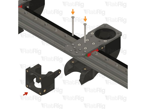
2x M3x35 Countersink Screw
-
Feed the M3x35 screws into the toolhead plate, through the 4028 part cooling fan and tighten them into the printed sub-assembly.
-
Take care not to over tighten the screws as you can damage the printed parts. Avoid using a ball end hex key, as they are more prone to damaging the sensitive M3 countersink screw head.
-
-
-
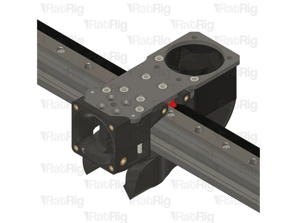
rr_vc4_toolhead_front_idex_t1 assembly
-
2x M3x35 Countersink screw
-
The M3x40 countersink screws must go through the holes on the front assembly and thread into the duct assembly.
-
Take care not to over tighten the screws as you can damage the printed parts
-
Avoid using a ball end hex key, as they are more prone to damaging the sensitive M3 countersink screw head.
-
-
-
rr_vc4_toolhead_fan_grille
-
2x M3x35 Cap Head Screw
-
Feed the M3x35 cap head screws through the grille (pay close attention to its orientation), the aluminium plate and the 4028 fan, tightening them into the back printed part.
-
Take care not to over tighten the screws as you can damage the printed parts
-
Avoid using a ball end hex key, as they are more prone to damaging the sensitive M3 countersink screw head.
-
-
-
Insert the belt in the designated slot, and ensure the belt end is fed from behind the screw.
-
Pull the belt end and gently place it inside the groove.
-
The belt teeth must be facing the front of the machine.
-
-
-
Rat Rig toolhead front belt clamp
-
Lever the belt clamp against the exposed screw section and place it inside the belt slot.
-
M4x10 Countersink Screw
-
Tighten the M4x10 screw making sure the teeth of the belt clamp mesh with the belt
-
Pay attention to seating the notch on the belt clamp on the exposed screw section. Pull on the belt to make sure it's secured properly.
-
Take care not to over tighten the screws as you can damage the printed parts.
-
-
-
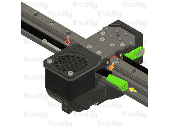
Feed the T1 belt through the designated hole at the rear of Toolhead T0, ensure that the belt is correctly seated on all idlers.
-
Carefully check that the belt is not pinched or obstructed by any part of Toolhead T0 during the process.
-
-
-
Feed the belt inside the slot on the back part of the toolhead.
-
Leave 10-20mm of the belt tip extending out to allow for easy manipulation during assembly.
-
Rat Rig toolhead back belt clamp
-
M3x35 Cap Head Screw
-
Tighten the M3x35 cap head screw while securely holding the belt end to prevent it from being pulled in.
-
Cut the excess belt.
-
-
-
Phaetus Rapido V2 UHF Hotend
-
4x M2.5x6 Countersink Screw
-
PTFE tube - 24.5mm
-
Remove the two countersink screws on top of the rapido
-
Remove the V6-style adapter, it is not required for the RatRig toolhead
-
-
-
Refer to Steps 20, 21, 22 and 23 to ensure the rapido is correctly positioned.
-
-
-
4x M2.5x6 Countersink Screw
-
Tighten the M2.5x6 Countersink Screws to secure the hotend to the plate.
-
Avoid using a ball end hex key, as they are more prone to damaging the sensitive M2.5 countersink screw head.
-
PTFE tube - 24.5mm
-
Insert the PTFE tube in to the marked hole and push it until it stops.
-
-
-
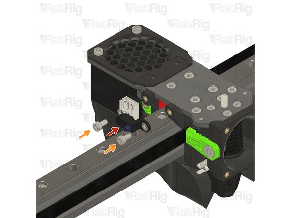
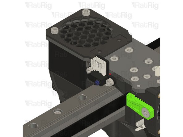
Rat Rig X Endstop
-
2x M3x6 Cap Head Screw
-
Tighten the M3x6 screws to secure the X endstop to the toolhead.
-
Take care not to over tighten the M3x6 screws as you can damage the printed parts.
-
-
-
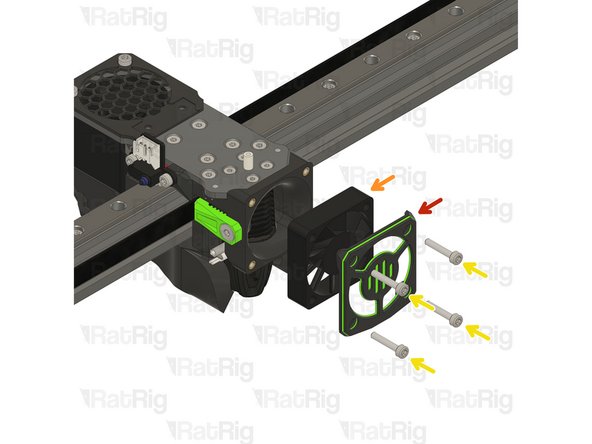
1x rr_vc4_toolhead_shroud
-
40x10mm 24V Axial Fan
-
4x M3x16 Cap Head Screw
-
Remove the sacrificial layers from the back of the rr_vc4_toolhead_shroud
-
-
-
Rat Rig toolhead fan shroud printed part
-
40x10mm 24V Axial Fan
-
The wires should be positioned where the arrow points.
-
4x M3x16 Cap Head Screw
-
Insert the M3x16 screws into the Rat Rig toolhead shroud printed part, through the 40mm fan, and fasten them into the Rat Rig toolhead front.
-
Take care not to over tighten the M3x16 screws as you can damage the printed parts.
-
Pay special attention to the fan airflow, it should blow the air towards the hot end heat sink. Most fans have a small arrow indicating the airflow. If not, the the fan label should be facing the hotend.
-
-
-
1x LDO Orbiter V2
-
2x M3x8 Cap Head Screw
-
Follow Step 33 to prepare the orbiter extruder
-
-
-
LDO Orbiter V2
-
2x M3x8 Cap Head Screw
-
Carefully align the extruder with the PTFE tube.
-
Insert the M3x8 screws into the LDO Orbiter V2 and fasten them to the Rat Rig toolhead plate.
-
Take care not to over tighten the M3x8 screws as you can strip the toolhead plate threads
-
Thread the hex standoff on to the LDO Orbiter V2 screw.
-
Do not overtighten the hex standoffs. They are brass and it is possible to strip the threads.
-
-
-
5x M3x8 Cap Head Screw
-
2x M3x35 Cap Head Screw
-
1x Hex standoff M3x20x4.5
-
rr_vc4_toolhead_toolboard_vertical
-
BIGTREETECH EBB42 USB/CAN TOOLBOARD V1.2
-
TMC2209 driver heatsink (included in the EBB42 box)
-
Remove the adhesive backing from the heatsink and gently press it onto the TMC2209 driver.
-
-
-
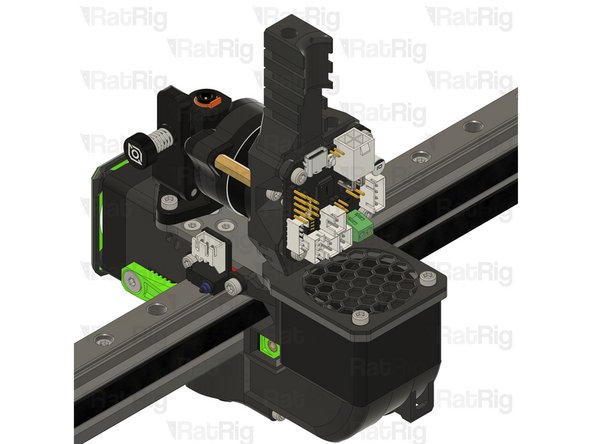
rr_vc4_toolhead_toolboard_vertical
-
Insert the M3x35 screws into the Rat Rig toolhead vertical toolboard mount printed part and secure it onto the toolhead.
-
Take care not to over tighten the M3x35 screws as you can damage the printed parts.
-
1x M3x8 Cap Head Screw
-
Insert the M3x8 screw through the printed part and into the thread to attach it to hex standoff.
-
-
-
BIGTREETECH EBB42 USB/CAN TOOLBOARD V1.2
-
4x M3x8 Cap Head Screw
-
Insert the M3x8 screws into the toolboard and thread them into the Rat Rig toolhead vertical toolboard mount printed part
-
-
-
Skip this Step if you are just upgrading your V-Core 4 hybrid to IDEX
-
Continue with the next guide: 10. Gantry Alignment
-